EP0750124B1 - Vorspannungseinstelleinrichtung und Verfahren - Google Patents
Vorspannungseinstelleinrichtung und Verfahren Download PDFInfo
- Publication number
- EP0750124B1 EP0750124B1 EP19960304608 EP96304608A EP0750124B1 EP 0750124 B1 EP0750124 B1 EP 0750124B1 EP 19960304608 EP19960304608 EP 19960304608 EP 96304608 A EP96304608 A EP 96304608A EP 0750124 B1 EP0750124 B1 EP 0750124B1
- Authority
- EP
- European Patent Office
- Prior art keywords
- actuating means
- axial
- radial
- housing
- radial actuating
- Prior art date
- Legal status (The legal status is an assumption and is not a legal conclusion. Google has not performed a legal analysis and makes no representation as to the accuracy of the status listed.)
- Expired - Lifetime
Links
- 230000036316 preload Effects 0.000 title claims description 31
- 238000000034 method Methods 0.000 title claims description 14
- 239000000463 material Substances 0.000 claims description 7
- 230000004323 axial length Effects 0.000 claims description 5
- 230000014759 maintenance of location Effects 0.000 claims description 5
- 230000000694 effects Effects 0.000 claims description 4
- 230000006835 compression Effects 0.000 claims description 3
- 238000007906 compression Methods 0.000 claims description 3
- 230000008602 contraction Effects 0.000 claims description 2
- 230000003247 decreasing effect Effects 0.000 description 4
- HZEWFHLRYVTOIW-UHFFFAOYSA-N [Ti].[Ni] Chemical compound [Ti].[Ni] HZEWFHLRYVTOIW-UHFFFAOYSA-N 0.000 description 3
- 239000000956 alloy Substances 0.000 description 3
- 229910045601 alloy Inorganic materials 0.000 description 3
- 230000007246 mechanism Effects 0.000 description 2
- 241000256247 Spodoptera exigua Species 0.000 description 1
- 238000010276 construction Methods 0.000 description 1
- 238000006073 displacement reaction Methods 0.000 description 1
- 238000005516 engineering process Methods 0.000 description 1
- 230000020169 heat generation Effects 0.000 description 1
- 230000004044 response Effects 0.000 description 1
- 230000000717 retained effect Effects 0.000 description 1
- 235000012431 wafers Nutrition 0.000 description 1
Images

Classifications
-
- F—MECHANICAL ENGINEERING; LIGHTING; HEATING; WEAPONS; BLASTING
- F16—ENGINEERING ELEMENTS AND UNITS; GENERAL MEASURES FOR PRODUCING AND MAINTAINING EFFECTIVE FUNCTIONING OF MACHINES OR INSTALLATIONS; THERMAL INSULATION IN GENERAL
- F16C—SHAFTS; FLEXIBLE SHAFTS; ELEMENTS OR CRANKSHAFT MECHANISMS; ROTARY BODIES OTHER THAN GEARING ELEMENTS; BEARINGS
- F16C25/00—Bearings for exclusively rotary movement adjustable for wear or play
- F16C25/06—Ball or roller bearings
- F16C25/08—Ball or roller bearings self-adjusting
-
- F—MECHANICAL ENGINEERING; LIGHTING; HEATING; WEAPONS; BLASTING
- F16—ENGINEERING ELEMENTS AND UNITS; GENERAL MEASURES FOR PRODUCING AND MAINTAINING EFFECTIVE FUNCTIONING OF MACHINES OR INSTALLATIONS; THERMAL INSULATION IN GENERAL
- F16C—SHAFTS; FLEXIBLE SHAFTS; ELEMENTS OR CRANKSHAFT MECHANISMS; ROTARY BODIES OTHER THAN GEARING ELEMENTS; BEARINGS
- F16C2202/00—Solid materials defined by their properties
- F16C2202/20—Thermal properties
- F16C2202/28—Shape memory material
-
- F—MECHANICAL ENGINEERING; LIGHTING; HEATING; WEAPONS; BLASTING
- F16—ENGINEERING ELEMENTS AND UNITS; GENERAL MEASURES FOR PRODUCING AND MAINTAINING EFFECTIVE FUNCTIONING OF MACHINES OR INSTALLATIONS; THERMAL INSULATION IN GENERAL
- F16C—SHAFTS; FLEXIBLE SHAFTS; ELEMENTS OR CRANKSHAFT MECHANISMS; ROTARY BODIES OTHER THAN GEARING ELEMENTS; BEARINGS
- F16C2229/00—Setting preload
Definitions
- This invention relates generally to preloaded bearings as used in spindles, axles or shafts and, more particularly, to a preload adjustment apparatus for use with preloaded bearings.
- the spindle In order for a machine tool spindle to maintain high accuracy under varying load conditions, the spindle must have a high degree of stiffness. Stiffness is generally obtained by using angular contact ball bearings mounted in pairs such that the bearings are preloaded against each other. That is, a thrust load is applied such that the bearing balls are forced tightly against the raceways.
- Preloading the bearings to obtain the required stiffness increases the stresses in the bearings, causing heat generation. This reduces bearing life and limits operating speed.
- bearing life and operating speed can be improved.
- a mechanical apparatus for varying the preload is described in US-A-4,657,412.
- Preload can also be varied using a piezoceramic actuator as described in US-A-4,850,719.
- a D.C. potential is applied to interfaces of multiple piezoelectric wafers in response to varying load conditions to control bearing stiffness.
- current piezoelectric actuator technology produces only small displacements, the ability to compensate for thermal expansion and control stiffness is severely limited.
- a preload adjustment apparatus for use with preloaded bearings mounted within a housing, characterised by a first radial actuating means for selective radial engagement with the housing such that axial movement of the first radial actuating means relative to the housing is prevented; second radial actuating means for selective radial engagement with the housing such that axial movement of the second radial actuating means relative to the housing is prevented; axial actuating means between the first and second radial actuating means for selective expansion and contraction of the axial distance between the first and second radial actuating means; and retention means for maintaining contact between the axial actuating means and the first radial actuating means and the second radial actuating means.
- a method for adjusting the preload of preloaded bearings mounted within a housing characterised by radially moving a first radial actuating means into engagement with the housing such that axial movement of the first radial actuating means relative to the housing is prevented; changing the axial length of an axial actuating means between the first and a second radial actuating means such that the axial distance between the first and second radial actuating means is changed; radially moving the second radial actuating means into engagement with the housing such that axial movement of the second radial actuating means relative to the housing is prevented; radially moving the first radial actuating means out of engagement with the housing such that axial movement of the first radial actuating means relative to the housing is not prevented; and changing the axial length of the axial actuating means between the first and second radial actuating means such that the axial distance between the first and second radial actuating means is changed.
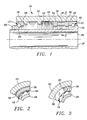
- Figure 1 illustrates an apparatus for adjusting the preload of first and second preloaded bearings 10 and 12 mounted within a housing 14 of a machine tool spindle or similar device.
- Outer rings 16 and 18 of the preloaded bearings 10 and 12 are mounted on an outer housing member 20 and inner rings 22 and 24 of the preloaded bearings 10 and 12 are mounted on an inner housing member 26.
- the inner ring 24 may be integral with the inner housing member 26 and the inner ring 22 may be retained axially by a threaded collar 28, as shown.
- the outer ring 16 is axially restrained by a shoulder 30 and the outer ring 18 is slidably movable with respect to the cylindrical inner surface 32 of the outer housing member 20.
- a first radial actuating clamp or means 34 is selectively movable radially to engage the housing 14 such that axial movement of the first radial actuating means 34 relative to the housing 14 is prevented.
- a second radial actuating clamp or means 36 is selectively movable radially to engage the housing 14 such that axial movement of the second radial actuating means 36 relative to the housing 14 is prevented.
- the radial actuating means 34 and 36 engage the outer housing member 20; however, a reversed configuration with engagement of the inner housing member 26 may also be used.
- Axial actuating means 38 between the first and second radial actuating means 34 and 36 is selectively movable to expand and contract the axial distance between the first and second radial actuating means 34 and 36.
- the axial actuating mens 38 may be made of a piezoceramic material and may have a hollow cylindrical configuration, as illustrated in Figure 2.
- the axial actuating means 38 may be a plurality of axial elements 40.
- the axial elements 40 may be three rods distributed circumferentially within the housing 14, as illustrated in Figure 3, and may be actuated independently.
- the housing 14 may include additional structure, not shown, to maintain the spacing and alignment of the axial elements 40.
- Retention or biasing means 42 such as a compression spring between the shoulder 43 and first radial actuator means 34, for example, may be used to maintain contact between the axial actuating means 38 and radial actuating means 34 and 36.
- the biasing means 42 may be designed to exert a predetermined force when the radial actuating means 34 and 36 are not clamped against the housing 14 and when the axial actuating means 38 is contracted to its minimum axial length.
- the biasing means 42 may be omitted and the axial actuating means 38 may be bonded or otherwise fixed to the radial actuating means 34 and 36 to maintain the desired contact.
- the first radial actuating means 34 is moved radially into engagement with the housing 14 such that axial movement of the first radial actuating means relative to the housing 14 is prevented, and the second radial actuating means 36 is moved out of engagement with the housing 14 such that axial movement of the second radial actuating means 36 relative to the housing 14 is not prevented.
- the axial actuating means 38 is expanded such that the axial distance between the first and second radial actuating means 34 and 36 is increased.
- the second radial actuating means 36 is moved radially into engagement with the housing 14 such that axial movement of the second radial actuating means 36 relative to the housing 14 is prevented.
- the first radial actuating means 34 is moved radially out of engagement with the housing 14 such that axial movement of the first radial actuating means 34 relative to the housing is not prevented.
- the axial actuating means 38 is contracted such that the axial distance between first and second radial actuating means is decreased.
- the process is reversed. That is, when the first radial actuating means 34 is clamped against the housing 14 and the second radial actuating means 36 is free to move relative to the housing 14, the axial actuating means 38 is contracted such that the axial distance between the first and second radial actuating means 36 is decreased.
- the second radial actuating means 36 is clamped against the housing 14 and the first radial actuating means 34 is unclamped while the axial actuating means 38 is expanded such that the distance between the first and second radial actuating means is increased.
- the sequence is repeated through multiple iterations, each decreasing the preload a small amount, until the desired preload is reached.
- the process of increasing or decreasing the preload can be considered to be a form of walking along the housing in a series of one-legged steps, or a movement similar to that of an inchworm.
- Controlling the preload can be done by counting the steps taken by the axial actuator or by adding a load monitor for direct reading of the preload to provide feedback. If multiple axial actuators are used as illustrated in Figure 3, a load monitor may be added for each axial actuator element to allow feedback control of each axial actuator separately to ensure that the preload is balanced along the circumference of the preloaded bearings.
- the simplest configuration for the radial actuator means 34 and 36 is a uniform ring.
- many variations that expand or contract against the housing 14 may be used, of which a few are illustrated in Figures 4 to 8.
- Figure 4 illustrates a split ring 44 with a linear actuator 46.
- Figures 5 and 6 illustrate multiple segments 48 and 50 separated by linear actuators 52 and 54, respectively.
- the engaging surfaces of the housing 14 and radial actuator means 34 and 36 may be grooved or otherwise configured to resist axial sliding movement.
- Figures 7 and 8 illustrate another configuration for the radial actuator means 34 and 36 comprising a collet-like device.
- a slotted ring 56 includes slots that form fingers 58.
- the contracting links 64 may be made of titanium-nickel (shape memory) alloy or another contracting material.
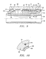
- Figures 9 and 10 illustrate a further embodiment similar to that of Figures 1 and 3 but including additional housing structure and a different form of radial actuating means.
- the outer housing member 66 is similar to the outer housing member 20 of Figure 1, including the shoulders 30 and 43 and cylindrical inner surface 32.
- the outer housing member 66 includes a reduced inner diameter portion 68 having a plurality of longitudinal bores, each receiving one axial actuating element 70 and radial actuating means 72 and 74.
- the radial actuating means may be cylindrical and may engage the respective longitudinal bore of the housing over the cylindrical surface of the radial actuating means, not merely in the radial directions.
- the axial actuating element 70 may be fixed to the radial actuating means 72 and 74 or may be maintained in contact with those elements by an optional preload spring 76.
- the apparatus has particular advantages when used with piezoelectric axial actuators with short strokes, other types of axial actuators such as those using magnetostrictive, titanium-nickel (shape memory) alloys, and thermopolymer materials, for example, may also be used.
- the radial actuating means 34 and 36 may use magnetostrictive, titanium-nickel (shape memory) alloys, thermopolymer materials and other mechanisms in addition to piezoelectric materials to effect the desired clamping.
- each of the actuating means is electrically activated.
- the apparatus for adjusting the preload of preloaded bearings is not limited by a short single stroke of an axial actuator.
- the apparatus uses iterations to overcome effects of thermal expansion and control preload for variations in rotational speed and other parameters.
- the apparatus may be used continually to monitor and control preload during operation of the machine spindle or other device.
- the present apparatus results in uniform axial stiffness in both axial directions.
Landscapes
- Engineering & Computer Science (AREA)
- General Engineering & Computer Science (AREA)
- Mechanical Engineering (AREA)
- Support Of The Bearing (AREA)
Claims (19)
- Einrichtung zum Einstellen einer Vorspannung zur Verwendung mit vorgespannten Lagern (10, 12), die innerhalb eines Gehäuses (14) angebracht sind, gekennzeichnet durch ein erstes radiales Betätigungsmittel (34) für einen wahlweisen radialen Eingriff mit dem Gehäuse (14) derart, daß eine axiale Bewegung des ersten radialen Betätigungsmittels (34) relativ zu dem Gehäuse verhindert ist; ein zweites radiales Betätigungsmittel (36) für einen wahlweisen radialen Eingriff mit dem Gehäuse (14) derart, daß eine axiale Bewegung des zweiten radialen Betätigungsmittels (36) relativ zu dem Gehäuse verhindert ist; ein axiales Betätigungsmittel (38) zwischen den ersten und zweiten radialen Betätigungsmitteln (34, 36) für ein wahlweises Ausdehnen und Vermindern des axialen Abstands zwischen den ersten und zweiten radialen Betätigungsmitteln; und ein Haltemittel (42) zum Aufrechterhalten der Berührung zwischen dem axialen Betätigungsmittel und dem ersten radialen Betätigungsmittel und dem zweiten radialen Betätigungsmittel.
- Einrichtung nach Anspruch (1), bei der die ersten und zweiten radialen Betätigungsmittel (34, 36) radial nach außen bewegbar sind, um eine Bewegung der ersten und zweiten radialen Betätigungsmittel relativ zu dem Gehäuse (14) zu verhindern.
- Einrichtung nach Anspruch 1 oder 2, bei der wenigstens eines der Lager (10, 12) gleitfähig in dem Gehäuse (14) bewegbar ist.
- Einrichtung nach Anspruch 1, 2 oder 3, bei der das Haltemittel (42) eine Druckfeder ist, die eine minimale Vorspannung liefert.
- Einrichtung nach einem der vorhergehenden Ansprüche, bei der das axiale Betätigungsmittel (38) eine rohrförmige Gestalt hat und um eine Achse der Lager (10, 12) herum angeordnet ist.
- Einrichtung nach einem der Ansprüche 1 bis 4, bei der die ersten und zweiten radialen Betätigungsmittel (34, 36) ringförmig sind und das axiale Betätigungsmittel (38) eine Vielzahl von axialen Elementen aufweist, die längs des Umfangs der ersten und zweiten radialen Betätigungsmittel verteilt sind.
- Einrichtung nach einem der vorhergehenden Ansprüche, bei der wenigstens ein Teil des axialen Betätigungsmittels (38) aus einem piezoelektrischen Material hergestellt ist.
- Einrichtung nach einem der vorhergehenden Ansprüche, bei der wenigstens ein Teil der ersten und zweiten radialen Betätigungsmittel (34, 36) aus einem piezoelektrischen Material hergestellt ist.
- Einrichtung nach einem der vorhergehenden Ansprüche, bei der das axiale Betätigungsmittel an den ersten und zweiten radialen Betätigungsmitteln derart befestigt ist, daß eine Berührung zwischen dem axialen Betätigungsmittel und den ersten und zweiten radialen Betätigungsmitteln aufrecht erhalten wird.
- Verfahren zum Einstellen der Vorspannung von vorgespannten Lagern (10, 12), die innerhalb eines Gehäuses (14) angebracht sind, gekennzeichnet durch radiales Bewegen eines ersten radialen Betätigungsmittels (34) in Eingriff mit dem Gehäuse (14) derart, daß eine axiale Bewegung des ersten radialen Betätigungsmittels relativ zu dem Gehäuse verhindert ist; Verändern der axialen Länge eines axialen Betätigungsmittels (38) zwischen dem ersten und einem zweiten radialen Betätigungsmittel (34, 36) derart, daß der axiale Abstand zwischen den ersten und zweiten radialen Betätigungsmitteln verändert wird; radiales Bewegen des zweiten radialen Betätigungsmittels (36) in Eingriff mit dem Gehäuse (14) derart, daß eine axiale Bewegung des zweiten radialen Betätigungsmittels relativ zu dem Gehäuse verhindert ist; radiales Bewegen des ersten radialen Betätigungsmittels (34) außer Eingriff mit dem Gehäuse derart, daß eine axiale Bewegung des ersten radialen Betätigungsmittels relativ zu dem Gehäuse nicht verhindert ist; und Verändern der axialen Länge des axialen Betätigungsmittels zwischen den ersten und zweiten radialen Betätigungsmitteln derart, daß der axiale Abstand zwischen den ersten und zweiten radialen Betätigungsmitteln verändert wird.
- Verfahren nach Anspruch 10, bei dem ferner eines der ersten und zweiten radialen Betätigungsmittel (34, 36) gegen das axiale Betätigungsmittel (38) derart vorgespannt wird, daß eine minimale Vorspannung aufrecht erhalten wird.
- Verfahren nach Anspruch 10 oder 11, bei dem ferner das axiale Betätigungsmittel (38) mit den ersten und zweiten radialen Betätigungsmitteln derart verbunden wird, daß eine Berührung zwischen dem axialen Betätigungsmittel und den ersten und zweiten radialen Betätigungsmitteln aufrecht erhalten wird.
- Verfahren nach Anspruch 10, 11 oder 12, bei dem die Schritte wiederholt werden, bis eine vorbestimmte Vorspannung erreicht ist.
- Verfahren nach einem der Ansprüche 10 bis 13, bei dem die radiale Bewegung der ersten und zweiten radialen Betätigungsmittel zum Bewirken eines Eingriffs mit dem Gehäuse radial nach außen gerichtet ist.
- Verfahren nach einem der Ansprüche 10 bis 14, bei dem wenigstens eines der vorgespannten Lager (10, 12) relativ zu dem Gehäuse (14) gleitfähig bewegbar ist.
- Verfahren nach einem der Ansprüche 10 bis 15, bei dem das Haltemittel (42) eine Druckfeder ist und eine minimale Vorspannung auf die vorgespannten Lager (10, 12) schafft.
- Verfahren nach einem der Ansprüche 10 bis 16, bei dem das axiale Betätigungsmittel rohrförmig ist und um eine Achse der Lager (10, 12) herum angeordnet ist.
- Verfahren nach einem der Ansprüche 10 bis 16, bei dem die ersten und zweiten radialen Betätigungsmittel (34, 36) ringförmig sind und das axiale Betätigungsmittel (38) eine Vielzahl von axialen Elementen aufweist, die in Umfangsrichtung längs der radialen Betätigungsmittel mit Abstand voneinander angeordnet sind.
- Verfahren nach Anspruch 18, bei dem die axialen Elemente unabhängig voneinander bewegbar sind.
Applications Claiming Priority (2)
| Application Number | Priority Date | Filing Date | Title |
|---|---|---|---|
| US38195P | 1995-06-21 | 1995-06-21 | |
| US381 | 1995-06-21 |
Publications (3)
| Publication Number | Publication Date |
|---|---|
| EP0750124A2 EP0750124A2 (de) | 1996-12-27 |
| EP0750124A3 EP0750124A3 (de) | 1998-06-03 |
| EP0750124B1 true EP0750124B1 (de) | 1999-11-17 |
Family
ID=21691293
Family Applications (1)
| Application Number | Title | Priority Date | Filing Date |
|---|---|---|---|
| EP19960304608 Expired - Lifetime EP0750124B1 (de) | 1995-06-21 | 1996-06-21 | Vorspannungseinstelleinrichtung und Verfahren |
Country Status (3)
| Country | Link |
|---|---|
| EP (1) | EP0750124B1 (de) |
| CA (1) | CA2179477A1 (de) |
| DE (1) | DE69605154T2 (de) |
Families Citing this family (6)
| Publication number | Priority date | Publication date | Assignee | Title |
|---|---|---|---|---|
| IT1315864B1 (it) * | 2000-03-15 | 2003-03-26 | Umbra Cuscinetti Spa | Dispositivo per la misurazione e la regolazione del precarico sucuscinetto. |
| DE102004024851A1 (de) * | 2004-05-19 | 2005-12-22 | Fag Kugelfischer Ag & Co. Ohg | Lageranordnung zur Lagerung wenigstens eines Maschinenteiles |
| US20060023985A1 (en) * | 2004-07-27 | 2006-02-02 | Mircea Gradu | Adaptive bearing system containing a piezoelectric actuator for controlling setting |
| DE102005027082A1 (de) * | 2005-06-11 | 2006-12-14 | Daimlerchrysler Ag | Lagerungsvorrichtung |
| DE102009024337A1 (de) * | 2009-06-09 | 2010-12-16 | Oerlikon Leybold Vacuum Gmbh | Vakuumpumpe |
| DE102013210692A1 (de) * | 2013-06-07 | 2014-12-11 | Schaeffler Technologies Gmbh & Co. Kg | Aktive Lagervorrichtung |
Family Cites Families (4)
| Publication number | Priority date | Publication date | Assignee | Title |
|---|---|---|---|---|
| US3902084A (en) * | 1974-05-30 | 1975-08-26 | Burleigh Instr | Piezoelectric electromechanical translation apparatus |
| US4850719A (en) * | 1988-09-12 | 1989-07-25 | The Torrington Company | Bearing with adjustable stiffness |
| US4874979A (en) * | 1988-10-03 | 1989-10-17 | Burleigh Instruments, Inc. | Electromechanical translation apparatus |
| JPH039116A (ja) * | 1989-06-06 | 1991-01-17 | Brother Ind Ltd | ころがり軸受用自動予圧調整装置 |
-
1996
- 1996-06-19 CA CA 2179477 patent/CA2179477A1/en not_active Abandoned
- 1996-06-21 EP EP19960304608 patent/EP0750124B1/de not_active Expired - Lifetime
- 1996-06-21 DE DE69605154T patent/DE69605154T2/de not_active Expired - Fee Related
Also Published As
| Publication number | Publication date |
|---|---|
| EP0750124A2 (de) | 1996-12-27 |
| EP0750124A3 (de) | 1998-06-03 |
| DE69605154T2 (de) | 2000-08-17 |
| DE69605154D1 (de) | 1999-12-23 |
| CA2179477A1 (en) | 1996-12-22 |
Similar Documents
| Publication | Publication Date | Title |
|---|---|---|
| US5564840A (en) | Preload adjustment apparatus and method | |
| EP0214505B1 (de) | Zapflageranordnungen | |
| US5051005A (en) | Variable preload bearing apparatus | |
| US4850719A (en) | Bearing with adjustable stiffness | |
| US5263381A (en) | Ball screw | |
| CA1088604A (en) | Bearing assembly for machine tool spindles | |
| EP0750124B1 (de) | Vorspannungseinstelleinrichtung und Verfahren | |
| TWI601887B (zh) | Bearing mechanism | |
| KR930007554A (ko) | 그리퍼 부재를 구비한 콜릿 척 | |
| US6508592B1 (en) | Device for measuring and adjusting preloading on bearings | |
| WO1998039123A1 (en) | Hydraulic pressurizing arrangements | |
| USRE34310E (en) | Variable preload bearing apparatus | |
| JP4174268B2 (ja) | 旋回軸受け | |
| US1251449A (en) | Clamping device for ball-bearings. | |
| JPH0724604A (ja) | 予圧可変式スピンドルユニットとその制御方法 | |
| JPH02279203A (ja) | 予圧可変式スピンドルユニット | |
| US4904095A (en) | Mounting arrangement for bearings | |
| JPH08294802A (ja) | 主軸装置 | |
| JP2023013087A (ja) | 転がり軸受 | |
| JP2679249B2 (ja) | 予圧可変式軸受装置 | |
| JP2005163868A (ja) | 軸受装置 | |
| JP2538406Y2 (ja) | 軸受支持装置 | |
| JPH052802U (ja) | 予圧可変式スピンドルユニツト | |
| JPH0512491Y2 (de) | ||
| US20190234462A1 (en) | Chabot true-axis bearing |
Legal Events
| Date | Code | Title | Description |
|---|---|---|---|
| PUAI | Public reference made under article 153(3) epc to a published international application that has entered the european phase |
Free format text: ORIGINAL CODE: 0009012 |
|
| AK | Designated contracting states |
Kind code of ref document: A2 Designated state(s): DE FI FR GB |
|
| PUAL | Search report despatched |
Free format text: ORIGINAL CODE: 0009013 |
|
| AK | Designated contracting states |
Kind code of ref document: A3 Designated state(s): DE FI FR GB |
|
| 17P | Request for examination filed |
Effective date: 19980818 |
|
| GRAG | Despatch of communication of intention to grant |
Free format text: ORIGINAL CODE: EPIDOS AGRA |
|
| 17Q | First examination report despatched |
Effective date: 19990202 |
|
| GRAG | Despatch of communication of intention to grant |
Free format text: ORIGINAL CODE: EPIDOS AGRA |
|
| GRAH | Despatch of communication of intention to grant a patent |
Free format text: ORIGINAL CODE: EPIDOS IGRA |
|
| GRAH | Despatch of communication of intention to grant a patent |
Free format text: ORIGINAL CODE: EPIDOS IGRA |
|
| GRAA | (expected) grant |
Free format text: ORIGINAL CODE: 0009210 |
|
| AK | Designated contracting states |
Kind code of ref document: B1 Designated state(s): DE FI FR GB |
|
| REF | Corresponds to: |
Ref document number: 69605154 Country of ref document: DE Date of ref document: 19991223 |
|
| ET | Fr: translation filed | ||
| PLBE | No opposition filed within time limit |
Free format text: ORIGINAL CODE: 0009261 |
|
| STAA | Information on the status of an ep patent application or granted ep patent |
Free format text: STATUS: NO OPPOSITION FILED WITHIN TIME LIMIT |
|
| 26N | No opposition filed | ||
| REG | Reference to a national code |
Ref country code: GB Ref legal event code: IF02 |
|
| PGFP | Annual fee paid to national office [announced via postgrant information from national office to epo] |
Ref country code: GB Payment date: 20030619 Year of fee payment: 8 Ref country code: FR Payment date: 20030619 Year of fee payment: 8 |
|
| PGFP | Annual fee paid to national office [announced via postgrant information from national office to epo] |
Ref country code: FI Payment date: 20030623 Year of fee payment: 8 |
|
| PGFP | Annual fee paid to national office [announced via postgrant information from national office to epo] |
Ref country code: DE Payment date: 20030630 Year of fee payment: 8 |
|
| PG25 | Lapsed in a contracting state [announced via postgrant information from national office to epo] |
Ref country code: GB Free format text: LAPSE BECAUSE OF NON-PAYMENT OF DUE FEES Effective date: 20040621 Ref country code: FI Free format text: LAPSE BECAUSE OF NON-PAYMENT OF DUE FEES Effective date: 20040621 |
|
| PG25 | Lapsed in a contracting state [announced via postgrant information from national office to epo] |
Ref country code: DE Free format text: LAPSE BECAUSE OF NON-PAYMENT OF DUE FEES Effective date: 20050101 |
|
| GBPC | Gb: european patent ceased through non-payment of renewal fee |
Effective date: 20040621 |
|
| PG25 | Lapsed in a contracting state [announced via postgrant information from national office to epo] |
Ref country code: FR Free format text: LAPSE BECAUSE OF NON-PAYMENT OF DUE FEES Effective date: 20050228 |
|
| REG | Reference to a national code |
Ref country code: FR Ref legal event code: ST |