EP0748891A1 - Procédé de compensation en température des mesures d'un capteur de turbidité dans un lave-linge ou un lave-vaisselle automatique - Google Patents
Procédé de compensation en température des mesures d'un capteur de turbidité dans un lave-linge ou un lave-vaisselle automatique Download PDFInfo
- Publication number
- EP0748891A1 EP0748891A1 EP96103813A EP96103813A EP0748891A1 EP 0748891 A1 EP0748891 A1 EP 0748891A1 EP 96103813 A EP96103813 A EP 96103813A EP 96103813 A EP96103813 A EP 96103813A EP 0748891 A1 EP0748891 A1 EP 0748891A1
- Authority
- EP
- European Patent Office
- Prior art keywords
- turbidity sensor
- temperature
- turbidity
- sensor
- measurement
- Prior art date
- Legal status (The legal status is an assumption and is not a legal conclusion. Google has not performed a legal analysis and makes no representation as to the accuracy of the status listed.)
- Granted
Links
Images


Classifications
-
- D—TEXTILES; PAPER
- D06—TREATMENT OF TEXTILES OR THE LIKE; LAUNDERING; FLEXIBLE MATERIALS NOT OTHERWISE PROVIDED FOR
- D06F—LAUNDERING, DRYING, IRONING, PRESSING OR FOLDING TEXTILE ARTICLES
- D06F39/00—Details of washing machines not specific to a single type of machines covered by groups D06F9/00 - D06F27/00
-
- A—HUMAN NECESSITIES
- A47—FURNITURE; DOMESTIC ARTICLES OR APPLIANCES; COFFEE MILLS; SPICE MILLS; SUCTION CLEANERS IN GENERAL
- A47L—DOMESTIC WASHING OR CLEANING; SUCTION CLEANERS IN GENERAL
- A47L15/00—Washing or rinsing machines for crockery or tableware
- A47L15/42—Details
- A47L15/4297—Arrangements for detecting or measuring the condition of the washing water, e.g. turbidity
-
- D—TEXTILES; PAPER
- D06—TREATMENT OF TEXTILES OR THE LIKE; LAUNDERING; FLEXIBLE MATERIALS NOT OTHERWISE PROVIDED FOR
- D06F—LAUNDERING, DRYING, IRONING, PRESSING OR FOLDING TEXTILE ARTICLES
- D06F34/00—Details of control systems for washing machines, washer-dryers or laundry dryers
- D06F34/14—Arrangements for detecting or measuring specific parameters
- D06F34/22—Condition of the washing liquid, e.g. turbidity
-
- G—PHYSICS
- G01—MEASURING; TESTING
- G01N—INVESTIGATING OR ANALYSING MATERIALS BY DETERMINING THEIR CHEMICAL OR PHYSICAL PROPERTIES
- G01N21/00—Investigating or analysing materials by the use of optical means, i.e. using sub-millimetre waves, infrared, visible or ultraviolet light
- G01N21/17—Systems in which incident light is modified in accordance with the properties of the material investigated
- G01N21/47—Scattering, i.e. diffuse reflection
- G01N21/49—Scattering, i.e. diffuse reflection within a body or fluid
- G01N21/53—Scattering, i.e. diffuse reflection within a body or fluid within a flowing fluid, e.g. smoke
- G01N21/534—Scattering, i.e. diffuse reflection within a body or fluid within a flowing fluid, e.g. smoke by measuring transmission alone, i.e. determining opacity
-
- D—TEXTILES; PAPER
- D06—TREATMENT OF TEXTILES OR THE LIKE; LAUNDERING; FLEXIBLE MATERIALS NOT OTHERWISE PROVIDED FOR
- D06F—LAUNDERING, DRYING, IRONING, PRESSING OR FOLDING TEXTILE ARTICLES
- D06F2103/00—Parameters monitored or detected for the control of domestic laundry washing machines, washer-dryers or laundry dryers
- D06F2103/16—Washing liquid temperature
-
- D—TEXTILES; PAPER
- D06—TREATMENT OF TEXTILES OR THE LIKE; LAUNDERING; FLEXIBLE MATERIALS NOT OTHERWISE PROVIDED FOR
- D06F—LAUNDERING, DRYING, IRONING, PRESSING OR FOLDING TEXTILE ARTICLES
- D06F2103/00—Parameters monitored or detected for the control of domestic laundry washing machines, washer-dryers or laundry dryers
- D06F2103/20—Washing liquid condition, e.g. turbidity
Definitions
- the invention relates to a method for temperature compensation of the measured values of a turbidity sensor, which is installed in a location of a water-carrying household appliance, preferably an automatic washing machine or dishwasher, with a process control using a microprocessor, and a light transmitter and a light receiver for the illumination of the contains wash liquor located within the measuring section.
- the turbidity of the wash liquor can be recorded as a process parameter and can be used to optimize the washing process. Since the turbidity sensor is located near the wash liquor, there is a thermal coupling between the turbidity sensor and the wash liquor. The temperature of the wash liquor can fluctuate between approximately 10 ° and 95 ° in normal operation, so that the turbidity sensor is also exposed to strong temperature fluctuations.
- the turbidity sensor works according to an optical method and consists of a transmitter (e.g. an LED) that emits light in the near infrared range and an optical receiver (photo transistor or photo diode or photo resistor) that converts the optical infrared signal into a proportional electrical signal.
- a transmitter e.g. an LED
- an optical receiver photo transistor or photo diode or photo resistor
- the transmitter e.g. infrared LED
- the receiver used e.g. photo transistor
- temperature compensation of the turbidity sensor is required in all devices in which the turbidity sensor is exposed to major temperature fluctuations, for example in washing machines or dishwashers.
- a washing machine with a device for measuring the contamination state of the wash liquor is known.
- This device also uses an electro-optical turbidity sensor, which is initially of a process containing several turbidity measurements is to be calibrated.
- This calibration relates to a reference value of the turbidity, which should correspond to a measurement definition of zero.
- the turbidity sensor is charged with pure tap water or with air and the measurement value determined in this way is defined as zero.
- the known device does not take into account that the ambient temperature of the turbidity sensor can fluctuate greatly and has a considerable influence on the magnitude of the turbidity measurement.
- the turbidity sensor must therefore be considered as an overall system, the Parameters are to be determined by tests. This applies in particular to the temperature coefficients of the electronic components of the turbidity sensor, since these are very strongly reflected in the measurement result.
- the temperature coefficient determined is also dependent on the respective operating point. This applies to the receiver (e.g. photo transistor) as well as the transmitter (e.g. IR LED).
- the temperature coefficient depends on the collector-emitter voltage and, in the case of the IR LED, on the forward current. With a constant forward current of the IR LED, the temperature coefficient of the IR LED does not change, but depending on the turbidity, the collector-emitter voltage of the phototransistor and thus its temperature coefficient changes. For this reason, you cannot count on a constant compensation factor for temperature compensation, but must dynamically adjust the compensation factor.
- Fig. 1 shows the temperature coefficient of a turbidity sensor over the temperature range of interest for wash liquors when using the so-called transmitted light method.
- the IR-LED SFH484 was used as the transmitter and the photo transistor SFH309F as the receiver.
- the transmission current of the LED was 5 mA during the measurement and an artificial turbidity was generated by a plastic strip.
- the sensor was in a climate chamber during the measurement. Measurements were taken during the cooling phase. The measurement results in a temperature coefficient of -6.6 mV / K or -0.95% per Kelvin.
- the temperature coefficient for IR LEDs is usually between -0.7% and -0.5% per Kelvin, depending on the semiconductor material used.
- the temperature range to which the turbidity sensor is exposed in the worst case is approximately 85 ° Kelvin, namely from approximately 10 ° to approximately 95 ° Celsius. Assuming that the temperature coefficient would be 0.95% / K, this results in a drift of the output signal of 80.75% without changing the turbidity. For the test without turbidity with a temperature coefficient of 0.52% / K, there is still a drift of 44.2% under these boundary conditions. Static temperature compensation is also possible, but then only applies to a certain working point, which means that the sensor is very restricted in its working area.
- the invention is therefore based on the object of obtaining correct turbidity measurements for all temperatures in the relevant range and for all turbidity variants in a method described at the outset. Temperature compensation of the sensor is absolutely necessary. As can be seen from the examples, however, no generally applicable temperature coefficient can be specified.
- this object is achieved in that the temperature coefficient of the turbidity sensor is calculated for each working point and is stored in the software for evaluating the measurement results of the turbidity sensor as a correction value and is used to correct the respective measurement result as a function of the temperature applied to the turbidity sensor.
- Temperature compensation is therefore only possible by dynamically adapting the compensation according to the invention to the respective operating point.
- a measurement result is first registered on the turbidity sensor and the operating point of the turbidity sensor is determined therefrom. Furthermore, after the immediately following or simultaneous measurement of the ambient temperature of the turbidity sensor, taking into account the measured value of the ambient temperature and the working point, the correction value is calculated and added to the measurement result.
- Dynamic temperature compensation can therefore be achieved best and particularly cost-effectively by means of a software-controlled evaluation of the turbidity signal.
- the temperature coefficient is determined for each possible working point of the sensor and integrated into the evaluation software.
- the sensor is supplemented by a temperature sensor so that the associated temperature can be determined at every working point of the sensor.
- the ambient temperature of the turbidity sensor is first measured and the operating point of the turbidity sensor is determined therefrom. Furthermore, a compensation value is calculated from the deviation of the determined working point from the typical working point of the turbidity sensor, by which the input variable of the turbidity sensor is to be changed for the subsequent turbidity measurement.
- the invention makes it possible to determine the turbidity of liquids which are subject to temperature fluctuations during the measurement.
- the measured values obtained are free from errors due to temperature influences.
- Temperature monitoring can simultaneously protect the components from being destroyed by operating temperatures that are too high.
- the temperature sensor can also be used to monitor the lye temperature. Therefore, no special temperature sensor is required per se for the temperature compensation of the turbidity signal.
- a temperature sensor e.g. an NTC resistor, a PTC resistor or a thermocouple can be used.
- LED, laser diode, incandescent lamp, glow lamp, fluorescent tube or similar light sources can be used as the light source.
- Suitable receiving elements are photo transistor, photo diode, photo resistor, photo element, photo cell or a similar receiving element.
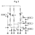
- Fig. 3 shows the circuit for a turbidity sensor with temperature compensation according to the invention.
- the turbidity sensor essentially consists of the IR LED D1, the phototransistor Q2 and the temperature sensor (NTC or PTC resistor) R4.
- the transmitter is formed by the control of the IR LED by means of a pulse width modulated signal (PWM signal) which is present at resistor R1.
- PWM signal pulse width modulated signal
- the resistor R1 forms a low-pass filter with the capacitor C1, the corner frequency of which must be significantly higher than the frequency of the PWM signal. This generates an analog voltage from the PWM signal that is proportional to the pulse duty factor of the PWM signal. This voltage is at the base of transistor Q1, which also defines the voltage across resistor R2.
- the transistor Q1 works here as a voltage-controlled current source for the IR LED located in the collector branch.
- the current through the IR LED is equal to the collector current, which corresponds approximately to the emitter current (neglecting the very low base current).
- the emitter current is determined by the voltage drop across R2. This voltage drop is brought out via the low-pass filter, consisting of R7 and C4, as output signal OUT-IR and is proportional to the current through the IR-LED.
- the phototransistor Q2 is connected in series with the resistor R3 in order to convert the photocurrent of the transistor into a proportional voltage which drops across R3.
- the capacitor C2 then smoothes the signal before it is made available as an output signal OUT-PH via the low-pass filter, consisting of R6 and C3.
- Temperature compensation requires temperature measurement using a temperature sensor.
- the resistors R4 and R5 form a voltage divider. Its divider voltage is temperature dependent because R4 is an NTC resistor. This circuit part is used to measure the temperature of the turbidity sensor, which, when evaluated, becomes the signal OUT-NTC, which is led out of R8 and C5 via the low-pass filter.
- a circuit board 1 serves as a bridge for two carriers 2 and 3, of which one carrier 2 carries a phototransistor 4 and the other carrier 3 an infrared light-emitting diode 5 (IR-LED).
- IR-LED infrared light-emitting diode
- This device can be made using a hole 6 on a support, e.g. a crossbar (not shown) for holding a transparent section 10 of a liquid line.
- the circuit board 1 also carries a plug-in trough 7 for the external electrical connection of the device.
- an NTC resistor 8 is also attached as a temperature sensor in thermal coupling to the light-emitting diode 5, which is also electrically connected to the printed circuit board 1 with its own lines 9 (indicated schematically).
Landscapes
- Engineering & Computer Science (AREA)
- Textile Engineering (AREA)
- Physics & Mathematics (AREA)
- Health & Medical Sciences (AREA)
- Life Sciences & Earth Sciences (AREA)
- Chemical & Material Sciences (AREA)
- Analytical Chemistry (AREA)
- Biochemistry (AREA)
- General Health & Medical Sciences (AREA)
- General Physics & Mathematics (AREA)
- Immunology (AREA)
- Pathology (AREA)
- Investigating Or Analysing Materials By Optical Means (AREA)
- Washing And Drying Of Tableware (AREA)
- Control Of Washing Machine And Dryer (AREA)
Applications Claiming Priority (2)
| Application Number | Priority Date | Filing Date | Title |
|---|---|---|---|
| DE19521326 | 1995-06-12 | ||
| DE19521326A DE19521326A1 (de) | 1995-06-12 | 1995-06-12 | Verfahren zur Temperaturkompensation der Meßwerte eines Trübungssensors in einer automatischen Wasch- oder Geschirrspülmaschine |
Publications (2)
| Publication Number | Publication Date |
|---|---|
| EP0748891A1 true EP0748891A1 (fr) | 1996-12-18 |
| EP0748891B1 EP0748891B1 (fr) | 1999-09-08 |
Family
ID=7764174
Family Applications (1)
| Application Number | Title | Priority Date | Filing Date |
|---|---|---|---|
| EP96103813A Expired - Lifetime EP0748891B1 (fr) | 1995-06-12 | 1996-03-11 | Procédé de compensation en température des mesures d'un capteur de turbidité dans un lave-linge ou un lave-vaisselle automatique |
Country Status (10)
| Country | Link |
|---|---|
| US (1) | US5889192A (fr) |
| EP (1) | EP0748891B1 (fr) |
| KR (1) | KR100391939B1 (fr) |
| CN (1) | CN1080347C (fr) |
| AT (1) | ATE184335T1 (fr) |
| BR (1) | BR9602730A (fr) |
| DE (2) | DE19521326A1 (fr) |
| ES (1) | ES2138254T3 (fr) |
| PL (1) | PL180751B1 (fr) |
| TR (1) | TR199600277A2 (fr) |
Cited By (8)
| Publication number | Priority date | Publication date | Assignee | Title |
|---|---|---|---|---|
| EP0849390A2 (fr) * | 1996-12-18 | 1998-06-24 | Bosch-Siemens HausgerÀ¤te GmbH | Machine à laver à tambour avec une conduite de liquide en plusieurs parties |
| EP1335060A1 (fr) * | 2002-01-31 | 2003-08-13 | Elektromanufaktur Zangenstein, Hanauer GmbH & Co. KGaA | Capteur de turbidité avec capteur de température pour appareil ménager |
| EP1285830A3 (fr) * | 2001-08-16 | 2004-05-06 | Hella KG Hueck & Co. | Méthode pour compenser l'influence de la température sur la capacité d'émission d'un émetteur LED et/ou sur la sensibilité du récepteur |
| WO2005057190A1 (fr) * | 2003-12-15 | 2005-06-23 | Emz-Hanauer Gmbh & Co. Kgaa | Detecteur de turbidite |
| EP2664264A1 (fr) * | 2012-05-15 | 2013-11-20 | Electrolux Home Products Corporation N.V. | Procédé et dispositif de mesure de la turbidité |
| DE102015205382A1 (de) | 2015-03-25 | 2016-09-29 | BSH Hausgeräte GmbH | Betreiben eines Haushaltsgeräts |
| WO2016188705A1 (fr) * | 2015-05-28 | 2016-12-01 | BSH Hausgeräte GmbH | Dispositif et procédé pour déterminer la charge en salissures d'un bain de lavage |
| US20170234848A1 (en) * | 2016-02-16 | 2017-08-17 | Solteam Opto, Inc. | Water quality sensor suitable for automated production |
Families Citing this family (35)
| Publication number | Priority date | Publication date | Assignee | Title |
|---|---|---|---|---|
| DE19544135C2 (de) * | 1995-11-27 | 2002-10-24 | Bsh Bosch Siemens Hausgeraete | Verfahren zur Temperaturkompensation der Meßwerte einer Sensoreinrichtung für die Lichtdurchlässigkeit einer Wasch- oder Spülflüssigkeit in einer automatischen Wasch- oder Geschirrspülmaschine |
| DE19721976B4 (de) * | 1997-05-26 | 2008-07-24 | BSH Bosch und Siemens Hausgeräte GmbH | Verfahren zum Feststellen eines unzulässig hohen Verkalkungsgrades in einem wasserführenden Haushaltsgerät |
| DE19755360B4 (de) * | 1997-12-12 | 2006-01-12 | BSH Bosch und Siemens Hausgeräte GmbH | Verfahren zur Temperaturmessung in einem wasserführenden Haushaltsgerät und wasserführendes Haushaltsgerät |
| DE19806560B4 (de) * | 1998-02-17 | 2007-08-23 | BSH Bosch und Siemens Hausgeräte GmbH | Verfahren und Vorrichtung zum Waschen und/oder Spülen von Wäsche in Waschmaschinen bzw. Waschtrocknern |
| DE19806559B4 (de) * | 1998-02-17 | 2015-10-29 | BSH Hausgeräte GmbH | Verfahren und Vorrichtung zur Behandlung von Geschirr in Spülmaschinen |
| DE19831688C1 (de) * | 1998-07-15 | 2000-04-06 | Whirlpool Co | Optischer Sensor |
| AT2967U1 (de) * | 1998-08-25 | 1999-07-26 | Avl List Gmbh | Trübungsmessverfahren |
| US6519034B1 (en) * | 1998-12-16 | 2003-02-11 | Honeywell International Inc. | Oil quality sensor |
| DE19961113A1 (de) * | 1999-12-17 | 2001-06-21 | Bsh Bosch Siemens Hausgeraete | Transmissionsmeßvorrichtung |
| US6456375B1 (en) | 2001-02-20 | 2002-09-24 | Honeywell International Inc. | Focused laser light turbidity sensor apparatus and method for measuring very low concentrations of particles in fluids |
| US6567166B2 (en) | 2001-02-21 | 2003-05-20 | Honeywell International Inc. | Focused laser light turbidity sensor |
| US6544344B2 (en) | 2001-07-27 | 2003-04-08 | General Electric Company | Dishwasher including a turbidity sensor |
| DE50204937D1 (de) | 2002-02-14 | 2005-12-22 | Emz Hanauer Gmbh & Co Kgaa | Trübungssensoren mit angepasster Übertragungscharakteristik und Verfahren zum Herstellen derselben |
| DE10305093A1 (de) * | 2003-02-07 | 2004-08-19 | BSH Bosch und Siemens Hausgeräte GmbH | Verfahren und Vorrichtung zur Bestimmung und Überwachung von Verunreinigungszuständen unterschiedlicher Flüssigkeiten |
| CN100389318C (zh) * | 2003-07-28 | 2008-05-21 | emz-汉拿两合有限公司 | 供家用电器用的带温度检测的混浊度传感器 |
| US20050190370A1 (en) * | 2004-02-26 | 2005-09-01 | Rosemount Analytical Inc. | Turbidity sensing system with reduced temperature effects |
| DE102005010129A1 (de) * | 2004-03-05 | 2005-09-15 | Marquardt Gmbh | Elektrische Schaltungsanordnung für ein Elektrowerkzeug |
| CN100531661C (zh) * | 2004-04-12 | 2009-08-26 | 乐金电子(天津)电器有限公司 | 洗碗机的进程控制方法 |
| DE102004035848A1 (de) * | 2004-07-23 | 2006-03-23 | BSH Bosch und Siemens Hausgeräte GmbH | Verfahren zum Kalibrieren von Sensoren |
| DE102004047682A1 (de) * | 2004-09-30 | 2006-04-06 | Patent-Treuhand-Gesellschaft für elektrische Glühlampen mbH | LED-Array |
| US8157920B2 (en) * | 2007-12-12 | 2012-04-17 | Electrolux Home Products, Inc. | Control device for a dishwasher appliance and associated method |
| KR101054435B1 (ko) * | 2008-11-10 | 2011-08-05 | 엘지전자 주식회사 | 식기 세척기의 제어방법 |
| JP4909390B2 (ja) * | 2009-08-25 | 2012-04-04 | パナソニック株式会社 | 洗濯機 |
| US20110094544A1 (en) * | 2009-10-23 | 2011-04-28 | Premark Feg L.L.C. | Warewash machine with soil detection |
| ITTO20110407A1 (it) * | 2011-05-09 | 2012-11-10 | Illinois Tool Works | Dispositivo sensore ottico controllato |
| US8834646B2 (en) | 2011-05-16 | 2014-09-16 | General Electric Company | Turbidity sensor and related consumer appliance |
| CN102535098B (zh) * | 2012-02-20 | 2016-11-23 | 青岛海尔洗衣机有限公司 | 具有浊度检测判断的洗衣方法及其洗衣机 |
| CN102634960A (zh) * | 2012-03-28 | 2012-08-15 | 海尔集团公司 | 洗衣机的传感装置和洗衣机及其控制方法 |
| CN103645161A (zh) * | 2013-11-16 | 2014-03-19 | 中山欧麦克仪器设备有限公司 | 一种浊度检测装置 |
| CN105455757A (zh) * | 2014-09-01 | 2016-04-06 | 青岛海尔洗碗机有限公司 | 带校准功能的浊度检测系统、检测方法及洗碗机 |
| CN104792737A (zh) * | 2015-04-17 | 2015-07-22 | 上海众毅工业控制技术有限公司 | 一种高精度高准确性的浊度测量装置和方法 |
| US10390675B2 (en) | 2015-06-01 | 2019-08-27 | Illinois Tool Works Inc. | Warewash machine cleaning notification and in-situ dilution process |
| US20170290358A1 (en) * | 2016-04-08 | 2017-10-12 | John Bean Technologies Corporation | System and method for automated, continuous high temperature sterilization and filling of food products |
| US11153950B2 (en) | 2019-02-14 | 2021-10-19 | Orlaco Products B.V. | Replacement mirror system with IR LED overheating management |
| CN110420000B (zh) * | 2019-08-26 | 2021-01-05 | 佛山市百斯特电器科技有限公司 | 一种清洗模式的确定方法及洗碗机 |
Citations (7)
| Publication number | Priority date | Publication date | Assignee | Title |
|---|---|---|---|---|
| US4257708A (en) * | 1978-04-28 | 1981-03-24 | Tokyo Shibaura Denki Kabushiki Kaisha | Apparatus for measuring the degree of rinsing |
| US4492868A (en) * | 1981-11-25 | 1985-01-08 | Jelvestam Roland Einar | Device for measuring concentration of particles conveyed by a liquid |
| US4841157A (en) * | 1988-01-06 | 1989-06-20 | Downing Jr John P | Optical backscatter turbidimeter sensor |
| DE4139899A1 (de) * | 1991-12-04 | 1993-06-09 | Hoffmann, Alfred, Dr., 9200 Freiberg, De | Verfahren zur simultanmessung der truebung und des zeitlichen massenstromes suspendierter teilchen in fluessigkeiten |
| US5291626A (en) * | 1992-05-01 | 1994-03-08 | General Electric Company | Machine for cleansing articles |
| US5477576A (en) * | 1995-02-10 | 1995-12-26 | General Electric Company | Temperature compensation method for a turbidity sensor used in an appliance for washing articles |
| WO1996021390A1 (fr) * | 1995-01-10 | 1996-07-18 | General Electric Company | Systeme et procede de reglage du cycle de fonctionnement d'une machine a laver |
Family Cites Families (3)
| Publication number | Priority date | Publication date | Assignee | Title |
|---|---|---|---|---|
| GB1285977A (en) * | 1968-12-23 | 1972-08-16 | Gam Rad | Improved turbidimeter |
| US3586862A (en) * | 1969-09-15 | 1971-06-22 | Keene Corp | Apparatus for continuous detection and measurement of suspended solids in liquids |
| US5555583A (en) * | 1995-02-10 | 1996-09-17 | General Electric Company | Dynamic temperature compensation method for a turbidity sensor used in an appliance for washing articles |
-
1995
- 1995-06-12 DE DE19521326A patent/DE19521326A1/de not_active Withdrawn
-
1996
- 1996-03-11 ES ES96103813T patent/ES2138254T3/es not_active Expired - Lifetime
- 1996-03-11 EP EP96103813A patent/EP0748891B1/fr not_active Expired - Lifetime
- 1996-03-11 AT AT96103813T patent/ATE184335T1/de not_active IP Right Cessation
- 1996-03-11 DE DE59602986T patent/DE59602986D1/de not_active Expired - Lifetime
- 1996-04-03 TR TR96/00277A patent/TR199600277A2/xx unknown
- 1996-06-10 PL PL96314710A patent/PL180751B1/pl not_active IP Right Cessation
- 1996-06-11 BR BR9602730A patent/BR9602730A/pt not_active Application Discontinuation
- 1996-06-12 KR KR1019960021348A patent/KR100391939B1/ko not_active IP Right Cessation
- 1996-06-12 CN CN96110312A patent/CN1080347C/zh not_active Expired - Fee Related
-
1997
- 1997-06-17 US US08/877,101 patent/US5889192A/en not_active Expired - Fee Related
Patent Citations (8)
| Publication number | Priority date | Publication date | Assignee | Title |
|---|---|---|---|---|
| US4257708A (en) * | 1978-04-28 | 1981-03-24 | Tokyo Shibaura Denki Kabushiki Kaisha | Apparatus for measuring the degree of rinsing |
| US4492868A (en) * | 1981-11-25 | 1985-01-08 | Jelvestam Roland Einar | Device for measuring concentration of particles conveyed by a liquid |
| US4841157A (en) * | 1988-01-06 | 1989-06-20 | Downing Jr John P | Optical backscatter turbidimeter sensor |
| DE4139899A1 (de) * | 1991-12-04 | 1993-06-09 | Hoffmann, Alfred, Dr., 9200 Freiberg, De | Verfahren zur simultanmessung der truebung und des zeitlichen massenstromes suspendierter teilchen in fluessigkeiten |
| US5291626A (en) * | 1992-05-01 | 1994-03-08 | General Electric Company | Machine for cleansing articles |
| US5291626B1 (en) * | 1992-05-01 | 1996-05-21 | Gen Electric | Machine for cleansing articles |
| WO1996021390A1 (fr) * | 1995-01-10 | 1996-07-18 | General Electric Company | Systeme et procede de reglage du cycle de fonctionnement d'une machine a laver |
| US5477576A (en) * | 1995-02-10 | 1995-12-26 | General Electric Company | Temperature compensation method for a turbidity sensor used in an appliance for washing articles |
Cited By (11)
| Publication number | Priority date | Publication date | Assignee | Title |
|---|---|---|---|---|
| EP0849390A2 (fr) * | 1996-12-18 | 1998-06-24 | Bosch-Siemens HausgerÀ¤te GmbH | Machine à laver à tambour avec une conduite de liquide en plusieurs parties |
| TR199701590A3 (tr) * | 1996-12-18 | 1998-07-21 | Bosch-Siemens Hausgeraete Gmbh | Birden fazla bölümlü bir sivi iletim hattini haiz olan tamburlu çamasir makinesi. |
| EP0849390A3 (fr) * | 1996-12-18 | 1999-01-20 | Bosch-Siemens HausgerÀ¤te GmbH | Machine à laver à tambour avec une conduite de liquide en plusieurs parties |
| EP1285830A3 (fr) * | 2001-08-16 | 2004-05-06 | Hella KG Hueck & Co. | Méthode pour compenser l'influence de la température sur la capacité d'émission d'un émetteur LED et/ou sur la sensibilité du récepteur |
| EP1335060A1 (fr) * | 2002-01-31 | 2003-08-13 | Elektromanufaktur Zangenstein, Hanauer GmbH & Co. KGaA | Capteur de turbidité avec capteur de température pour appareil ménager |
| WO2005057190A1 (fr) * | 2003-12-15 | 2005-06-23 | Emz-Hanauer Gmbh & Co. Kgaa | Detecteur de turbidite |
| EP2664264A1 (fr) * | 2012-05-15 | 2013-11-20 | Electrolux Home Products Corporation N.V. | Procédé et dispositif de mesure de la turbidité |
| DE102015205382A1 (de) | 2015-03-25 | 2016-09-29 | BSH Hausgeräte GmbH | Betreiben eines Haushaltsgeräts |
| WO2016188705A1 (fr) * | 2015-05-28 | 2016-12-01 | BSH Hausgeräte GmbH | Dispositif et procédé pour déterminer la charge en salissures d'un bain de lavage |
| US20170234848A1 (en) * | 2016-02-16 | 2017-08-17 | Solteam Opto, Inc. | Water quality sensor suitable for automated production |
| US10254267B2 (en) * | 2016-02-16 | 2019-04-09 | Solteam Opto, Inc. | Water quality sensor suitable for automated production |
Also Published As
| Publication number | Publication date |
|---|---|
| TR199600277A2 (tr) | 1996-12-21 |
| PL314710A1 (en) | 1996-12-23 |
| DE19521326A1 (de) | 1996-12-19 |
| CN1145965A (zh) | 1997-03-26 |
| EP0748891B1 (fr) | 1999-09-08 |
| PL180751B1 (pl) | 2001-04-30 |
| KR970001698A (ko) | 1997-01-24 |
| DE59602986D1 (de) | 1999-10-14 |
| ES2138254T3 (es) | 2000-01-01 |
| KR100391939B1 (ko) | 2003-11-17 |
| US5889192A (en) | 1999-03-30 |
| CN1080347C (zh) | 2002-03-06 |
| BR9602730A (pt) | 1998-04-22 |
| ATE184335T1 (de) | 1999-09-15 |
Similar Documents
| Publication | Publication Date | Title |
|---|---|---|
| EP0748891B1 (fr) | Procédé de compensation en température des mesures d'un capteur de turbidité dans un lave-linge ou un lave-vaisselle automatique | |
| EP1039597B1 (fr) | Méthode de stabilisation de la puissance optique des diodes à l'emission de lumière et des lasers à diodes | |
| DE60217496T2 (de) | Steuersystem für einen abstimmbaren laser | |
| DE69627922T2 (de) | Sensor zur Feststellung feiner Teilchen wie Rauch | |
| DE102005014492B4 (de) | Näherungssensor | |
| EP0050306A2 (fr) | Dispositif de mesure à fibres optiques | |
| DE102007031480B4 (de) | Sensoreinrichtung und Verfahren zur Erfassung der Trübung von Spülflotte | |
| EP1754395B1 (fr) | Procede de stabilisation de la dependance a la temperature de l'emission lumineuse d'une del | |
| US5477576A (en) | Temperature compensation method for a turbidity sensor used in an appliance for washing articles | |
| DE4434666A1 (de) | Sensor | |
| DE10256429A1 (de) | Verfahren und Anordnung zum Messen eines modulierten Lichtsignals | |
| EP1475471B1 (fr) | Capteur de turbidité avec caractéristiques de transmission adaptées et procédé pour fabriquer celui-ci | |
| EP0479118A2 (fr) | Dispositif pour la stabilisation de la fréquence d'une diode laser | |
| DE19544135C2 (de) | Verfahren zur Temperaturkompensation der Meßwerte einer Sensoreinrichtung für die Lichtdurchlässigkeit einer Wasch- oder Spülflüssigkeit in einer automatischen Wasch- oder Geschirrspülmaschine | |
| DE4446775B4 (de) | Verfahren zur Kompensation der thermischen Offsetdrift von Sensoren | |
| EP0520302B1 (fr) | Dispositif de commande d'un système d'essuie-glaces | |
| EP0935742B1 (fr) | Module emetteur-recepteur pour capteurs a fibres de verre | |
| DE102013205605B4 (de) | Beleuchtung für ein Lichtlaufzeitmesssystem | |
| DE102013110814B4 (de) | Einrichtung zur Verfolgung der Qualität eines sich bewegenden linearen Textilmaterials, insbesondere eines Garns | |
| DE102014217028A1 (de) | Kochfeld mit Temperatursensor | |
| EP2211205A2 (fr) | Procédé de détection d'objets dans une zone de surveillance et capteur optique destiné à l'exécution du procédé | |
| DE602004010892T2 (de) | System und Verfahren zur Kontrolle von optischen Quellen, zum Beispiel Laserdioden, und zugehöriges Computerprogramm | |
| DE102010054447A1 (de) | Optischer Sensor zum Einbau in eine Waschmaschine oder Geschirrspülmaschine | |
| DE202007006342U1 (de) | Anordnung zur Driftkompensation von Dreibereichsfarbdetektionssystemen für Nichtselbstleuchter | |
| DE102018222485A1 (de) | Anzeigevorrichtung für ein Elektrowerkzeug |
Legal Events
| Date | Code | Title | Description |
|---|---|---|---|
| PUAI | Public reference made under article 153(3) epc to a published international application that has entered the european phase |
Free format text: ORIGINAL CODE: 0009012 |
|
| AK | Designated contracting states |
Kind code of ref document: A1 Designated state(s): AT CH DE ES FR GB IT LI |
|
| 17P | Request for examination filed |
Effective date: 19970505 |
|
| RAP1 | Party data changed (applicant data changed or rights of an application transferred) |
Owner name: BSH BOSCH UND SIEMENS HAUSGERAETE GMBH |
|
| GRAG | Despatch of communication of intention to grant |
Free format text: ORIGINAL CODE: EPIDOS AGRA |
|
| GRAG | Despatch of communication of intention to grant |
Free format text: ORIGINAL CODE: EPIDOS AGRA |
|
| GRAH | Despatch of communication of intention to grant a patent |
Free format text: ORIGINAL CODE: EPIDOS IGRA |
|
| 17Q | First examination report despatched |
Effective date: 19990226 |
|
| GRAH | Despatch of communication of intention to grant a patent |
Free format text: ORIGINAL CODE: EPIDOS IGRA |
|
| GRAA | (expected) grant |
Free format text: ORIGINAL CODE: 0009210 |
|
| AK | Designated contracting states |
Kind code of ref document: B1 Designated state(s): AT CH DE ES FR GB IT LI |
|
| REF | Corresponds to: |
Ref document number: 184335 Country of ref document: AT Date of ref document: 19990915 Kind code of ref document: T |
|
| REG | Reference to a national code |
Ref country code: CH Ref legal event code: NV Representative=s name: ISLER & PEDRAZZINI AG Ref country code: CH Ref legal event code: EP |
|
| ET | Fr: translation filed | ||
| GBT | Gb: translation of ep patent filed (gb section 77(6)(a)/1977) |
Effective date: 19990910 |
|
| REF | Corresponds to: |
Ref document number: 59602986 Country of ref document: DE Date of ref document: 19991014 |
|
| ITF | It: translation for a ep patent filed |
Owner name: STUDIO JAUMANN P. & C. S.N.C. |
|
| REG | Reference to a national code |
Ref country code: ES Ref legal event code: FG2A Ref document number: 2138254 Country of ref document: ES Kind code of ref document: T3 |
|
| PLBI | Opposition filed |
Free format text: ORIGINAL CODE: 0009260 |
|
| PLBF | Reply of patent proprietor to notice(s) of opposition |
Free format text: ORIGINAL CODE: EPIDOS OBSO |
|
| 26 | Opposition filed |
Opponent name: MIELE & CIE. GMBH & CO. Effective date: 20000608 |
|
| PLBF | Reply of patent proprietor to notice(s) of opposition |
Free format text: ORIGINAL CODE: EPIDOS OBSO |
|
| PLBF | Reply of patent proprietor to notice(s) of opposition |
Free format text: ORIGINAL CODE: EPIDOS OBSO |
|
| PLBO | Opposition rejected |
Free format text: ORIGINAL CODE: EPIDOS REJO |
|
| REG | Reference to a national code |
Ref country code: GB Ref legal event code: IF02 |
|
| PLBN | Opposition rejected |
Free format text: ORIGINAL CODE: 0009273 |
|
| STAA | Information on the status of an ep patent application or granted ep patent |
Free format text: STATUS: OPPOSITION REJECTED |
|
| 27O | Opposition rejected |
Effective date: 20011026 |
|
| PGFP | Annual fee paid to national office [announced via postgrant information from national office to epo] |
Ref country code: AT Payment date: 20050322 Year of fee payment: 10 |
|
| PG25 | Lapsed in a contracting state [announced via postgrant information from national office to epo] |
Ref country code: AT Free format text: LAPSE BECAUSE OF NON-PAYMENT OF DUE FEES Effective date: 20060311 |
|
| REG | Reference to a national code |
Ref country code: CH Ref legal event code: PCAR Free format text: ISLER & PEDRAZZINI AG;POSTFACH 1772;8027 ZUERICH (CH) |
|
| PGFP | Annual fee paid to national office [announced via postgrant information from national office to epo] |
Ref country code: ES Payment date: 20090325 Year of fee payment: 14 |
|
| PGFP | Annual fee paid to national office [announced via postgrant information from national office to epo] |
Ref country code: GB Payment date: 20090324 Year of fee payment: 14 Ref country code: CH Payment date: 20090325 Year of fee payment: 14 |
|
| PGFP | Annual fee paid to national office [announced via postgrant information from national office to epo] |
Ref country code: IT Payment date: 20090326 Year of fee payment: 14 |
|
| PGFP | Annual fee paid to national office [announced via postgrant information from national office to epo] |
Ref country code: FR Payment date: 20090318 Year of fee payment: 14 |
|
| REG | Reference to a national code |
Ref country code: CH Ref legal event code: PL |
|
| GBPC | Gb: european patent ceased through non-payment of renewal fee |
Effective date: 20100311 |
|
| REG | Reference to a national code |
Ref country code: FR Ref legal event code: ST Effective date: 20101130 |
|
| PG25 | Lapsed in a contracting state [announced via postgrant information from national office to epo] |
Ref country code: FR Free format text: LAPSE BECAUSE OF NON-PAYMENT OF DUE FEES Effective date: 20100331 |
|
| PG25 | Lapsed in a contracting state [announced via postgrant information from national office to epo] |
Ref country code: LI Free format text: LAPSE BECAUSE OF NON-PAYMENT OF DUE FEES Effective date: 20100331 Ref country code: CH Free format text: LAPSE BECAUSE OF NON-PAYMENT OF DUE FEES Effective date: 20100331 |
|
| PG25 | Lapsed in a contracting state [announced via postgrant information from national office to epo] |
Ref country code: GB Free format text: LAPSE BECAUSE OF NON-PAYMENT OF DUE FEES Effective date: 20100311 Ref country code: IT Free format text: LAPSE BECAUSE OF NON-PAYMENT OF DUE FEES Effective date: 20100311 |
|
| REG | Reference to a national code |
Ref country code: ES Ref legal event code: FD2A Effective date: 20110419 |
|
| PG25 | Lapsed in a contracting state [announced via postgrant information from national office to epo] |
Ref country code: ES Free format text: LAPSE BECAUSE OF NON-PAYMENT OF DUE FEES Effective date: 20110404 |
|
| PG25 | Lapsed in a contracting state [announced via postgrant information from national office to epo] |
Ref country code: ES Free format text: LAPSE BECAUSE OF NON-PAYMENT OF DUE FEES Effective date: 20100312 |
|
| PGFP | Annual fee paid to national office [announced via postgrant information from national office to epo] |
Ref country code: DE Payment date: 20120331 Year of fee payment: 17 |
|
| REG | Reference to a national code |
Ref country code: DE Ref legal event code: R119 Ref document number: 59602986 Country of ref document: DE Effective date: 20131001 |
|
| PG25 | Lapsed in a contracting state [announced via postgrant information from national office to epo] |
Ref country code: DE Free format text: LAPSE BECAUSE OF NON-PAYMENT OF DUE FEES Effective date: 20131001 |