EP0748030B1 - Vorrichtung zum Einpressen eines Nutverschlussstückes für rotierende elektrische Maschinen - Google Patents
Vorrichtung zum Einpressen eines Nutverschlussstückes für rotierende elektrische Maschinen Download PDFInfo
- Publication number
- EP0748030B1 EP0748030B1 EP96810320A EP96810320A EP0748030B1 EP 0748030 B1 EP0748030 B1 EP 0748030B1 EP 96810320 A EP96810320 A EP 96810320A EP 96810320 A EP96810320 A EP 96810320A EP 0748030 B1 EP0748030 B1 EP 0748030B1
- Authority
- EP
- European Patent Office
- Prior art keywords
- machine
- support frame
- force
- slot
- prismatic body
- Prior art date
- Legal status (The legal status is an assumption and is not a legal conclusion. Google has not performed a legal analysis and makes no representation as to the accuracy of the status listed.)
- Expired - Lifetime
Links
Images




Classifications
-
- H—ELECTRICITY
- H02—GENERATION; CONVERSION OR DISTRIBUTION OF ELECTRIC POWER
- H02K—DYNAMO-ELECTRIC MACHINES
- H02K15/00—Processes or apparatus specially adapted for manufacturing, assembling, maintaining or repairing of dynamo-electric machines
- H02K15/10—Applying solid insulation to windings, stators or rotors, e.g. applying insulating tapes
-
- H—ELECTRICITY
- H02—GENERATION; CONVERSION OR DISTRIBUTION OF ELECTRIC POWER
- H02K—DYNAMO-ELECTRIC MACHINES
- H02K15/00—Processes or apparatus specially adapted for manufacturing, assembling, maintaining or repairing of dynamo-electric machines
- H02K15/13—Applying slot closure means in the cores; Manufacture of slot closure means
-
- H—ELECTRICITY
- H02—GENERATION; CONVERSION OR DISTRIBUTION OF ELECTRIC POWER
- H02K—DYNAMO-ELECTRIC MACHINES
- H02K15/00—Processes or apparatus specially adapted for manufacturing, assembling, maintaining or repairing of dynamo-electric machines
- H02K15/50—Disassembling, repairing or modifying dynamo-electric machines
-
- Y—GENERAL TAGGING OF NEW TECHNOLOGICAL DEVELOPMENTS; GENERAL TAGGING OF CROSS-SECTIONAL TECHNOLOGIES SPANNING OVER SEVERAL SECTIONS OF THE IPC; TECHNICAL SUBJECTS COVERED BY FORMER USPC CROSS-REFERENCE ART COLLECTIONS [XRACs] AND DIGESTS
- Y10—TECHNICAL SUBJECTS COVERED BY FORMER USPC
- Y10T—TECHNICAL SUBJECTS COVERED BY FORMER US CLASSIFICATION
- Y10T29/00—Metal working
- Y10T29/49—Method of mechanical manufacture
- Y10T29/49002—Electrical device making
- Y10T29/49009—Dynamoelectric machine
-
- Y—GENERAL TAGGING OF NEW TECHNOLOGICAL DEVELOPMENTS; GENERAL TAGGING OF CROSS-SECTIONAL TECHNOLOGIES SPANNING OVER SEVERAL SECTIONS OF THE IPC; TECHNICAL SUBJECTS COVERED BY FORMER USPC CROSS-REFERENCE ART COLLECTIONS [XRACs] AND DIGESTS
- Y10—TECHNICAL SUBJECTS COVERED BY FORMER USPC
- Y10T—TECHNICAL SUBJECTS COVERED BY FORMER US CLASSIFICATION
- Y10T29/00—Metal working
- Y10T29/49—Method of mechanical manufacture
- Y10T29/49002—Electrical device making
- Y10T29/49009—Dynamoelectric machine
- Y10T29/49012—Rotor
-
- Y—GENERAL TAGGING OF NEW TECHNOLOGICAL DEVELOPMENTS; GENERAL TAGGING OF CROSS-SECTIONAL TECHNOLOGIES SPANNING OVER SEVERAL SECTIONS OF THE IPC; TECHNICAL SUBJECTS COVERED BY FORMER USPC CROSS-REFERENCE ART COLLECTIONS [XRACs] AND DIGESTS
- Y10—TECHNICAL SUBJECTS COVERED BY FORMER USPC
- Y10T—TECHNICAL SUBJECTS COVERED BY FORMER US CLASSIFICATION
- Y10T29/00—Metal working
- Y10T29/53—Means to assemble or disassemble
- Y10T29/5313—Means to assemble electrical device
- Y10T29/53143—Motor or generator
- Y10T29/53152—Means to position insulation
-
- Y—GENERAL TAGGING OF NEW TECHNOLOGICAL DEVELOPMENTS; GENERAL TAGGING OF CROSS-SECTIONAL TECHNOLOGIES SPANNING OVER SEVERAL SECTIONS OF THE IPC; TECHNICAL SUBJECTS COVERED BY FORMER USPC CROSS-REFERENCE ART COLLECTIONS [XRACs] AND DIGESTS
- Y10—TECHNICAL SUBJECTS COVERED BY FORMER USPC
- Y10T—TECHNICAL SUBJECTS COVERED BY FORMER US CLASSIFICATION
- Y10T29/00—Metal working
- Y10T29/53—Means to assemble or disassemble
- Y10T29/5313—Means to assemble electrical device
- Y10T29/53143—Motor or generator
- Y10T29/53161—Motor or generator including deforming means
-
- Y—GENERAL TAGGING OF NEW TECHNOLOGICAL DEVELOPMENTS; GENERAL TAGGING OF CROSS-SECTIONAL TECHNOLOGIES SPANNING OVER SEVERAL SECTIONS OF THE IPC; TECHNICAL SUBJECTS COVERED BY FORMER USPC CROSS-REFERENCE ART COLLECTIONS [XRACs] AND DIGESTS
- Y10—TECHNICAL SUBJECTS COVERED BY FORMER USPC
- Y10T—TECHNICAL SUBJECTS COVERED BY FORMER US CLASSIFICATION
- Y10T29/00—Metal working
- Y10T29/53—Means to assemble or disassemble
- Y10T29/53796—Puller or pusher means, contained force multiplying operator
- Y10T29/5383—Puller or pusher means, contained force multiplying operator having fluid operator
Definitions
- the invention relates to a device for pressing Groove closure piece, as in the preamble of the first claim is described.
- Such a device for pressing in a slot closure piece is e.g. known from CH 525 581.
- Arrangements for fixing the conductor bars or coils by means of slot closure pieces in the slots of electrical machines are known.
- the conductor bars or coils are pressed against the bottom of the groove by compensating strips and trapezoidal or dovetail-shaped wedges.
- a device for fixing the trapezoidal or dovetail-shaped wedges is known from the above-mentioned CH 525 581.
- a stamp presses against the end face of a lower wedge and presses it between compensating strips and an upper wedge, which is supported against recesses in the laminated core of an electrical machine .
- the stamp mentioned is connected to a pressure cylinder which is supported by cams during the pressing-in process of the wedges in radial air slots in the electrical machine.
- the invention has for its object a device for pressing in groove closing pieces, in the following Called wedging device, in the grooves of a rotating electrical machines of the type mentioned in that regard further develop that the wedging device during not against the stator laminated core supports, and that the slot closures only at their axial Position in the sheet metal package groove, and not in Machine longitudinal direction to be shifted.
- the slot locks are fixed evenly in the entire bore of the machine in a controlled manner from the wedging device to the stator lamination stack without the use of force.
- the slot locks are wedged at their axial machine longitudinal position, it being particularly advantageous if the force exerted on the rod or coil insulation by wedging the slot locks is selected to be greater than the shaking force during operation of the machine plus an additional force, the takes into account the aging of the winding parts.
- the advantages of the invention can be seen, inter alia, in the fact that the overall height of the wedging device is designed such that it can be introduced and carried out into the air gap between the stator sheet metal body and the rotor body of a rotating electrical machine.
- the wedge device can also be used in machines which are periodically parked for inspection purposes, the rotor of which remains installed in the stator.
- a so-called re-wedging of existing systems is particularly notable for its high cost-effectiveness because the time-consuming dismantling of the rotor is eliminated.
- 1 is generally the wedging device designated.
- This wedging device 1 consists in essentially from a collet 2 with a cam 3 and a force-generating device 4.
- the force-generating device Device 4 comprises a pressure cylinder 5, in which a Piston 6 is operated hydraulically. This piston 6 is over a linkage 7 with a stamp 8 connected to a Guide pin 9 guided in a bore 10 of the collet 2 is.
- FIG. 2 shows, the wedging device 1 with lifting devices 22 movably arranged on a support frame 23. Furthermore, video equipment is on this support frame 23 24, 25, 26, 27, or 42, 43, 44, 45, and mobile Magnetic carrier 28 attached.
- the video equipment consists of two cameras 24, 42 with camera mounts 25, 43 and two Mirror 26, 44 with mirror mounts 27, 45.
- the Cameras 24 with a mirror 26 on the support frame 23 installed that the area around the cam 3 visually is detectable.
- the second camera 42 with a mirror 44 is attached so that the area around the stamp 8 is captured becomes.
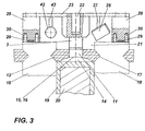
- 3 shows, are on the mobile magnetic carriers 28 (also FIG.
- a conductor bar is located in a groove 21 of the stator laminated core 18 20 inserted with insulation 19, and the groove 21 is by means of a tongue 14 and a dovetail groove wedge 12, which is laterally in recesses 17 of the stator core 18 supported, closed.
- Fig. 4 shows the wedging device 1 as it is on a slot closure piece 12, 14 is positioned. These slot lock pieces 12, 14 are closer with reference to FIGS. 5, 6 and 7 described.
- the wedge 12 has on its underside concave surface 16 and axial slots on the end faces 11.
- the tongue 14 has an upper, in the assembled state concave surface 16 of the groove wedge 12 facing convex surface 15. The convex and concave surfaces 15, 16 are in FIG. 3 evident.
- the function of the wedging device 1 is explained with reference to FIG. 4. If the pliers 2 with the punch 8 are positioned on a slot closing piece 12, 14, the wedging device 1 is moved in the direction of the slot closing piece 12, 14 with the lifting devices 22, the cam 3 sliding into the axial slot 11 of the slot wedge 12, and the punch 8 engages on an end face 13 of the tongue 14.
- the piston 6 is actuated hydraulically, the cam 3 and the plunger 8 move towards one another in the manner of a screw clamp.
- the tongue 14 is pushed under the slot wedge 12, whereby a force from the tongue 14 acts on the insulation 19 of the conductor bar 20 in the direction of the slot base. This force is chosen to be greater than the shaking force during operation of the machine plus an additional force that takes into account the aging of the winding parts.
- Each slot lock 12, 14 can thus be fixed in a controlled manner in a rotating electrical machine.
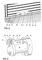
- FIG. 8 shows a section through the stator sheet metal body 18 and the rotor body 31 of an electrical machine with an intermediate one Air gap 32.
- this air gap 32 is on Carrier ropes 33 of the carrier frame 23 with wedging device 1 arranged with the pull cables 34 in the machine longitudinal direction 40 is movable.
- the Video equipment 24, 25, 26, 27 as shown in Fig. 2 is the positioning of the wedging device 1 Slot locks 12, 14.
- the video equipment is for this outside the air gap 32 on not shown Screens is connected.
- the support cables 33 and the pull cables 34 lead, as in FIG. 9 is shown, on both sides outside the air gap 32 to a carrier support 35 each.
- the carrier supports 35 are arranged on a radial fan 36 and each include Drive device 37 for the movement 38 of the suspension cables 33 in the circumferential direction and a drive device 39 for the Movement 40 of the wedging device 1 in the machine longitudinal direction.
- a force-generating device in the form of a toothed or threaded rod that is non-positively connected to an electric drive is conceivable in the sense of the invention.
Landscapes
- Engineering & Computer Science (AREA)
- Manufacturing & Machinery (AREA)
- Power Engineering (AREA)
- Manufacture Of Motors, Generators (AREA)
- Insulation, Fastening Of Motor, Generator Windings (AREA)
- Mechanical Operated Clutches (AREA)
Applications Claiming Priority (2)
| Application Number | Priority Date | Filing Date | Title |
|---|---|---|---|
| DE19520868 | 1995-06-08 | ||
| DE19520868A DE19520868A1 (de) | 1995-06-08 | 1995-06-08 | Vorrichtung zum Einpressen eines Nutzverschlußstückes für rotierende elektrische Maschinen |
Publications (3)
| Publication Number | Publication Date |
|---|---|
| EP0748030A2 EP0748030A2 (de) | 1996-12-11 |
| EP0748030A3 EP0748030A3 (de) | 1997-03-05 |
| EP0748030B1 true EP0748030B1 (de) | 2000-03-15 |
Family
ID=7763880
Family Applications (1)
| Application Number | Title | Priority Date | Filing Date |
|---|---|---|---|
| EP96810320A Expired - Lifetime EP0748030B1 (de) | 1995-06-08 | 1996-05-22 | Vorrichtung zum Einpressen eines Nutverschlussstückes für rotierende elektrische Maschinen |
Country Status (11)
| Country | Link |
|---|---|
| US (1) | US5778518A (cs) |
| EP (1) | EP0748030B1 (cs) |
| JP (1) | JPH099586A (cs) |
| KR (1) | KR970004239A (cs) |
| CN (1) | CN1093993C (cs) |
| AT (1) | ATE190773T1 (cs) |
| BR (1) | BR9602706A (cs) |
| CZ (1) | CZ155496A3 (cs) |
| DE (2) | DE19520868A1 (cs) |
| HR (1) | HRP960104A2 (cs) |
| HU (1) | HUP9601595A3 (cs) |
Cited By (1)
| Publication number | Priority date | Publication date | Assignee | Title |
|---|---|---|---|---|
| US9774232B2 (en) | 2011-05-10 | 2017-09-26 | General Electric Technology Gmbh | Cutting device |
Families Citing this family (10)
| Publication number | Priority date | Publication date | Assignee | Title |
|---|---|---|---|---|
| US7015616B2 (en) * | 2002-04-01 | 2006-03-21 | Honeywell International, Inc. | System and method for providing coil retention in the rotor windings of a high speed generator |
| US6864617B1 (en) * | 2003-10-02 | 2005-03-08 | General Electric Company | Retaining system for a rotor of a dynamoelectric machine |
| US7707710B2 (en) | 2007-07-31 | 2010-05-04 | General Electric Company | Tool for driving wedges or slides |
| KR101351279B1 (ko) * | 2012-10-10 | 2014-01-16 | 코오롱환경서비스주식회사 | 슬러지 이송건조장치 |
| US9748825B2 (en) * | 2015-03-11 | 2017-08-29 | Siemens Energy, Inc. | Tool for installing a wedge in a slot of a stator core |
| CN107425681A (zh) * | 2017-05-11 | 2017-12-01 | 广西桂冠电力股份有限公司大化水力发电总厂 | 立式水轮发电机定子线棒压紧方法及装置 |
| CN108551240B (zh) * | 2018-05-15 | 2019-09-17 | 雷磊 | 一种手工下线定子铁芯用槽楔插接辅助装置 |
| CN109347272A (zh) * | 2018-11-07 | 2019-02-15 | 哈尔滨电机厂有限责任公司 | 一种液压动力安装汽轮发电机定子槽楔的工艺方法 |
| CN109374041A (zh) * | 2018-11-29 | 2019-02-22 | 三集团有限公司北京分公司 | 发电机磁性槽楔检测系统及方法 |
| DE102019207248A1 (de) | 2019-05-17 | 2020-11-19 | Siemens Aktiengesellschaft | Prüffahrzeug |
Family Cites Families (11)
| Publication number | Priority date | Publication date | Assignee | Title |
|---|---|---|---|---|
| DE31961C (de) * | A. H. BOCK in Meifsen i. S | Achslagerung für Velocipede u. dergl | ||
| DD31961A (cs) * | ||||
| US1271365A (en) * | 1917-09-12 | 1918-07-02 | Albert Worth Reynolds Jr | Wrench. |
| US2695015A (en) * | 1952-06-26 | 1954-11-23 | Champion Mfg Company | Work-supporting carriage for masonry saws |
| DE1948025C3 (de) * | 1969-09-23 | 1974-06-27 | Brown, Boveri & Cie Ag, 6800 Mannheim | Vorrichtung zum Verschließen der Nuten einer elektrischen Maschine oder eines elektrischen Apparates mittels mehrteiliger, prismatischer Nutenverschlußstücke |
| JPH01214244A (ja) * | 1988-02-22 | 1989-08-28 | Toshiba Corp | 楔計測装置 |
| JP2735284B2 (ja) * | 1989-04-07 | 1998-04-02 | 株式会社東芝 | 回転電機の補修装置 |
| US5020234A (en) * | 1989-09-01 | 1991-06-04 | Westinghouse Electric Corp. | Prober for testing generator stator wedge tightness with rotor in place |
| ES2060890T3 (es) * | 1990-10-22 | 1994-12-01 | Asea Brown Boveri | Dispositivo para detectar descargas parciales en elementos de arrollamiento de una maquina electrica. |
| JP3215827B2 (ja) * | 1992-10-15 | 2001-10-09 | ティーディーケイ株式会社 | カメラ一体型装着ヘッド装置 |
| DE4327775A1 (de) * | 1993-08-18 | 1995-02-23 | Abb Management Ag | Nutverschlußanordnung |
-
1995
- 1995-06-08 DE DE19520868A patent/DE19520868A1/de not_active Withdrawn
-
1996
- 1996-02-22 KR KR1019960004215A patent/KR970004239A/ko not_active Withdrawn
- 1996-03-01 HR HR19520868.4A patent/HRP960104A2/hr not_active Application Discontinuation
- 1996-04-16 US US08/633,111 patent/US5778518A/en not_active Expired - Fee Related
- 1996-05-22 DE DE59604642T patent/DE59604642D1/de not_active Expired - Lifetime
- 1996-05-22 AT AT96810320T patent/ATE190773T1/de active
- 1996-05-22 EP EP96810320A patent/EP0748030B1/de not_active Expired - Lifetime
- 1996-05-29 CZ CZ961554A patent/CZ155496A3/cs unknown
- 1996-06-03 JP JP8140444A patent/JPH099586A/ja active Pending
- 1996-06-06 CN CN96108110A patent/CN1093993C/zh not_active Expired - Fee Related
- 1996-06-07 BR BR9602706A patent/BR9602706A/pt not_active Application Discontinuation
- 1996-06-07 HU HU9601595A patent/HUP9601595A3/hu unknown
Cited By (1)
| Publication number | Priority date | Publication date | Assignee | Title |
|---|---|---|---|---|
| US9774232B2 (en) | 2011-05-10 | 2017-09-26 | General Electric Technology Gmbh | Cutting device |
Also Published As
| Publication number | Publication date |
|---|---|
| CN1093993C (zh) | 2002-11-06 |
| CZ155496A3 (en) | 1996-12-11 |
| EP0748030A3 (de) | 1997-03-05 |
| BR9602706A (pt) | 1998-03-24 |
| JPH099586A (ja) | 1997-01-10 |
| HUP9601595A2 (en) | 1997-05-28 |
| CN1142132A (zh) | 1997-02-05 |
| ATE190773T1 (de) | 2000-04-15 |
| KR970004239A (ko) | 1997-01-29 |
| US5778518A (en) | 1998-07-14 |
| HRP960104A2 (en) | 1997-08-31 |
| HUP9601595A3 (en) | 1998-12-28 |
| DE59604642D1 (de) | 2000-04-20 |
| HU9601595D0 (en) | 1996-08-28 |
| EP0748030A2 (de) | 1996-12-11 |
| DE19520868A1 (de) | 1996-12-12 |
Similar Documents
| Publication | Publication Date | Title |
|---|---|---|
| EP0748030B1 (de) | Vorrichtung zum Einpressen eines Nutverschlussstückes für rotierende elektrische Maschinen | |
| EP0540893B1 (de) | Vorrichtung zum Verseilen von strangförmigem Gut insbesondere grösseren Querschnittes mit wechselnder Schlagrichtung | |
| EP0175075B1 (de) | Elektrische Maschine | |
| DE60125117T2 (de) | Gleitereinheit mit eingebautem Linearmotor mit beweglicher Spule | |
| EP3863161B1 (de) | Bestückungsvorrichtung und system umfassend eine bestückungsvorrichtung und einen rotor | |
| DE2817951A1 (de) | Laeufer fuer eine elektrische maschine | |
| DE1948025C3 (de) | Vorrichtung zum Verschließen der Nuten einer elektrischen Maschine oder eines elektrischen Apparates mittels mehrteiliger, prismatischer Nutenverschlußstücke | |
| DE19818150B4 (de) | Elektrische Maschine mit einem mit Dämpferstäben versehenen Rotor | |
| DE2262045A1 (de) | Turbogenerator | |
| DE2605593C3 (de) | Supraleitende Erregerwicklung für den Läufer eines Turbogenerators | |
| DE102005048731A1 (de) | Permanentmagnet-Rotor und Verfahren zur Montage von Permanentmagneten an einem Permanentmagnet-Rotor | |
| WO2023020786A1 (de) | Rotor mit einer haltevorrichtung für eine spulenvorrichtung, elektrische maschine mit einem rotor und kraftfahrzeug mit einer elektrischen maschine | |
| DE10244201A1 (de) | Elektrische Maschine sowie Verfahren zum Montieren einer solchen elektrischen Maschine | |
| DE9400080U1 (de) | Trägereinrichtung für eine Bürste | |
| DE1173178B (de) | Permanenterregte elektrische Maschine mit einem Dauermagnetbloecke enthaltenden Laeufer | |
| DE3334761C2 (cs) | ||
| EP0926802A2 (de) | Elektrische Maschine mit einem verspannten Wickelkopf | |
| DE19948490A1 (de) | Lineardirektantrieb | |
| DE3533748C2 (cs) | ||
| DE3624923A1 (de) | Stator einer elektrischen maschine mit direkt in das gehaeuse eingeblechtem statorblechkoerper und verfahren zu dessen herstellung | |
| DE2816671A1 (de) | Elektrischer generator | |
| DE2202604C2 (de) | Federnde Statorabstützung einer Synchronmaschine | |
| DE102018130518A1 (de) | Permanentmagnet-Rotor für einen bürstenlosen Elektromotor und Verfahren zur Montage eines Permanentmagnet-Rotors für einen bürstenlosen Elektromotor | |
| DE2612904A1 (de) | Vorrichtung zum anordnen von spulen und verfahren zum einrichten der vorrichtung fuer das anordnen von spulen in kernen mit verschiedenen axialen laengen | |
| DE2153551C3 (de) | Keilvorrichtung zum Festhalten eines Wicklungsstabes in einer Wicklungsnut einer rotierenden elektrischen Maschine |
Legal Events
| Date | Code | Title | Description |
|---|---|---|---|
| PUAI | Public reference made under article 153(3) epc to a published international application that has entered the european phase |
Free format text: ORIGINAL CODE: 0009012 |
|
| AK | Designated contracting states |
Kind code of ref document: A2 Designated state(s): AT CH DE DK ES FR GB IT LI PT SE |
|
| RAP1 | Party data changed (applicant data changed or rights of an application transferred) |
Owner name: ASEA BROWN BOVERI AG |
|
| PUAL | Search report despatched |
Free format text: ORIGINAL CODE: 0009013 |
|
| AK | Designated contracting states |
Kind code of ref document: A3 Designated state(s): AT CH DE DK ES FR GB IT LI PT SE |
|
| 17P | Request for examination filed |
Effective date: 19970808 |
|
| GRAG | Despatch of communication of intention to grant |
Free format text: ORIGINAL CODE: EPIDOS AGRA |
|
| GRAG | Despatch of communication of intention to grant |
Free format text: ORIGINAL CODE: EPIDOS AGRA |
|
| GRAH | Despatch of communication of intention to grant a patent |
Free format text: ORIGINAL CODE: EPIDOS IGRA |
|
| 17Q | First examination report despatched |
Effective date: 19990730 |
|
| GRAH | Despatch of communication of intention to grant a patent |
Free format text: ORIGINAL CODE: EPIDOS IGRA |
|
| GRAA | (expected) grant |
Free format text: ORIGINAL CODE: 0009210 |
|
| AK | Designated contracting states |
Kind code of ref document: B1 Designated state(s): AT CH DE DK ES FR GB IT LI PT SE |
|
| PG25 | Lapsed in a contracting state [announced via postgrant information from national office to epo] |
Ref country code: SE Free format text: THE PATENT HAS BEEN ANNULLED BY A DECISION OF A NATIONAL AUTHORITY Effective date: 20000315 Ref country code: IT Free format text: LAPSE BECAUSE OF FAILURE TO SUBMIT A TRANSLATION OF THE DESCRIPTION OR TO PAY THE FEE WITHIN THE PRE;WARNING: LAPSES OF ITALIAN PATENTS WITH EFFECTIVE DATE BEFORE 2007 MAY HAVE OCCURRED AT ANY TIME BEFORE 2007. THE CORRECT EFFECTIVE DATE MAY BE DIFFERENT FROM THE ONE RECORDED.SCRIBED TIME-LIMIT Effective date: 20000315 Ref country code: ES Free format text: THE PATENT HAS BEEN ANNULLED BY A DECISION OF A NATIONAL AUTHORITY Effective date: 20000315 |
|
| REF | Corresponds to: |
Ref document number: 190773 Country of ref document: AT Date of ref document: 20000415 Kind code of ref document: T |
|
| REG | Reference to a national code |
Ref country code: CH Ref legal event code: EP |
|
| REF | Corresponds to: |
Ref document number: 59604642 Country of ref document: DE Date of ref document: 20000420 |
|
| PG25 | Lapsed in a contracting state [announced via postgrant information from national office to epo] |
Ref country code: AT Free format text: LAPSE BECAUSE OF NON-PAYMENT OF DUE FEES Effective date: 20000522 |
|
| PG25 | Lapsed in a contracting state [announced via postgrant information from national office to epo] |
Ref country code: LI Free format text: LAPSE BECAUSE OF NON-PAYMENT OF DUE FEES Effective date: 20000531 Ref country code: CH Free format text: LAPSE BECAUSE OF NON-PAYMENT OF DUE FEES Effective date: 20000531 |
|
| PG25 | Lapsed in a contracting state [announced via postgrant information from national office to epo] |
Ref country code: PT Free format text: LAPSE BECAUSE OF FAILURE TO SUBMIT A TRANSLATION OF THE DESCRIPTION OR TO PAY THE FEE WITHIN THE PRESCRIBED TIME-LIMIT Effective date: 20000615 Ref country code: DK Free format text: LAPSE BECAUSE OF FAILURE TO SUBMIT A TRANSLATION OF THE DESCRIPTION OR TO PAY THE FEE WITHIN THE PRESCRIBED TIME-LIMIT Effective date: 20000615 |
|
| RAP2 | Party data changed (patent owner data changed or rights of a patent transferred) |
Owner name: ABB ALSTOM POWER (SCHWEIZ) AG |
|
| ET | Fr: translation filed | ||
| GBT | Gb: translation of ep patent filed (gb section 77(6)(a)/1977) |
Effective date: 20000601 |
|
| REG | Reference to a national code |
Ref country code: GB Ref legal event code: 732E |
|
| PLBE | No opposition filed within time limit |
Free format text: ORIGINAL CODE: 0009261 |
|
| STAA | Information on the status of an ep patent application or granted ep patent |
Free format text: STATUS: NO OPPOSITION FILED WITHIN TIME LIMIT |
|
| REG | Reference to a national code |
Ref country code: CH Ref legal event code: PL |
|
| 26N | No opposition filed | ||
| REG | Reference to a national code |
Ref country code: GB Ref legal event code: IF02 |
|
| PGFP | Annual fee paid to national office [announced via postgrant information from national office to epo] |
Ref country code: GB Payment date: 20020502 Year of fee payment: 7 |
|
| PGFP | Annual fee paid to national office [announced via postgrant information from national office to epo] |
Ref country code: DE Payment date: 20020511 Year of fee payment: 7 |
|
| PGFP | Annual fee paid to national office [announced via postgrant information from national office to epo] |
Ref country code: FR Payment date: 20020513 Year of fee payment: 7 |
|
| PG25 | Lapsed in a contracting state [announced via postgrant information from national office to epo] |
Ref country code: DE Free format text: LAPSE BECAUSE OF THE APPLICANT RENOUNCES Effective date: 20021221 |
|
| PG25 | Lapsed in a contracting state [announced via postgrant information from national office to epo] |
Ref country code: GB Free format text: LAPSE BECAUSE OF NON-PAYMENT OF DUE FEES Effective date: 20030522 |
|
| GBPC | Gb: european patent ceased through non-payment of renewal fee |
Effective date: 20030522 |
|
| PG25 | Lapsed in a contracting state [announced via postgrant information from national office to epo] |
Ref country code: FR Free format text: LAPSE BECAUSE OF NON-PAYMENT OF DUE FEES Effective date: 20040130 |
|
| REG | Reference to a national code |
Ref country code: FR Ref legal event code: ST |