EP0746643B1 - Fadenspinnen - Google Patents
Fadenspinnen Download PDFInfo
- Publication number
- EP0746643B1 EP0746643B1 EP95901276A EP95901276A EP0746643B1 EP 0746643 B1 EP0746643 B1 EP 0746643B1 EP 95901276 A EP95901276 A EP 95901276A EP 95901276 A EP95901276 A EP 95901276A EP 0746643 B1 EP0746643 B1 EP 0746643B1
- Authority
- EP
- European Patent Office
- Prior art keywords
- sub
- assemblies
- fibre
- assembly
- yarn
- Prior art date
- Legal status (The legal status is an assumption and is not a legal conclusion. Google has not performed a legal analysis and makes no representation as to the accuracy of the status listed.)
- Expired - Lifetime
Links
Images


Classifications
-
- D—TEXTILES; PAPER
- D02—YARNS; MECHANICAL FINISHING OF YARNS OR ROPES; WARPING OR BEAMING
- D02G—CRIMPING OR CURLING FIBRES, FILAMENTS, THREADS, OR YARNS; YARNS OR THREADS
- D02G3/00—Yarns or threads, e.g. fancy yarns; Processes or apparatus for the production thereof, not otherwise provided for
- D02G3/22—Yarns or threads characterised by constructional features, e.g. blending, filament/fibre
- D02G3/34—Yarns or threads having slubs, knops, spirals, loops, tufts, or other irregular or decorative effects, i.e. effect yarns
-
- D—TEXTILES; PAPER
- D02—YARNS; MECHANICAL FINISHING OF YARNS OR ROPES; WARPING OR BEAMING
- D02G—CRIMPING OR CURLING FIBRES, FILAMENTS, THREADS, OR YARNS; YARNS OR THREADS
- D02G3/00—Yarns or threads, e.g. fancy yarns; Processes or apparatus for the production thereof, not otherwise provided for
- D02G3/22—Yarns or threads characterised by constructional features, e.g. blending, filament/fibre
- D02G3/26—Yarns or threads characterised by constructional features, e.g. blending, filament/fibre with characteristics dependent on the amount or direction of twist
- D02G3/28—Doubled, plied, or cabled threads
- D02G3/281—Doubled, plied, or cabled threads using one drawing frame for two slivers and twisting of the slivers to a single yarn, i.e. spin-twisting
Definitions
- This invention relates generally to the processing of fibre assemblies.
- a particularly useful application is to the spinning of yarns, especially though not exclusively staple yarns, and in preferred aspects the invention provides a weavable or low pilling yarn from single or double rovings or slubbings.
- Two-strand yarns may be produced by spinning or twisting together two strands in which the fibre tails have been wrapped by an air-jet (eg Plyfil) or in which the alternating strand twist is trapped during the operation (eg Sirospun).
- Such yarns have enhanced strength and abrasion resistance relative to singles yarns but in worsted processing have an average cross-section of around 80 or more fibres. It would be very useful to produce a weavable singles yarn of a structure which may be of significantly smaller cross-section, with say around 50-60 fibres or less. However, singles yarns of such size to date have tended to have inadequate strength and abrasion resistance for weaving and knitting applications.
- the nip rollers are driven at a lower speed than the delivery speed of the front drafting rollers, a negative draft which induces an "overfeed" zone in which the fibres are found to randomly alter their positions at the nip. There is thus a random migration of the fibres between the core and the surface of the yarn.
- the drafted strand is allowed to spread sufficiently laterally for "sub-groupings" to form in which the fibres are false twisted to form separate sub-strands that are then twisted together in a recombined yarn.
- US patent 4418523 disclosed a notched roller for providing fancy yarns in spinning-twisting machines, where the core is false-twisted and wrapped with a filament.
- US 3 599 416 discloses an apparatus for and method of spinning yarn on which the pre-characterising sections of the independent claims are based.
- the yarn may be a singles yarn or otherwise but an object of one or more embodiments of the invention is to produce a singles yarn having the above property.
- a method of spinning a yarn comprising receiving and drafting an initial travelling fibre assembly, and drawing and taking up the fibre assembly characterized by dividing the initial travelling fibre assembly into a plurality of fibre sub-assemblies, causing the sub-assemblies to traverse different paths and then recombining them by twisting the sub-assemblies together, wherein said paths are sufficiently proximate for fibres to continuously transfer from one or more of said sub-assemblies and be drawn onto or into another or other sub-assemblies.
- the invention also provides, in its first aspect, apparatus for spinning a yarn comprising:
- the recombining means is effective to twist the sub-assemblies together such that the twist travels further back along said one of said fibre sub-assemblies, past the point of recombination, than for another fibre sub-assembly.
- this is effective to cause the fibre sub-assemblies to have different path lengths by which fibres transferring between the sub-assemblies have different axial tensions.
- a method of spinning a yarn comprising receiving and drafting an initial travelling fibre assembly, and drawing and taking up the fibre assembly characterized by dividing the initial travelling fibre assembly into a plurality of fibre sub-assemblies, causing said plurality of fibre sub-assemblies to traverse cyclically varying paths and then recombining them to form a yarn by twisting the sub-assemblies together.
- the invention also provides, in its second aspect, apparatus for spinning a yarn comprising:
- variation of the paths may comprise cyclically altering the relative lengths of the paths traversed by the sub-assemblies between their division from the fibre assembly and their twisting together.
- the paths traversed by the respective sub-assemblies are cyclically varied by braiding means for cyclically interchanging the relative lateral positions of the sub-assemblies, for example, by laying each sub-assembly across another sub-assembly and then returning the former to its original relative lateral position.
- the braiding means is preferably effective to enhance the intermingling of fibres between the sub-assemblies.
- the braiding is controlled according to a pre-determined sequence along the length of the moving fibre assembly selected to optimise fibre interactions.
- the braiding means is effective to create an intertwined fibre network prior to the insertion of twist.
- Such a network will in generally be quite distinct from the internal fibre structure which might be obtained by simply twisting randomly appearing sub-groupings, as proposed in the aforementioned WO94/01604.
- the braiding means also serves as said means for dividing the travelling fibre assembly into the plurality of sub-assemblies.
- Such means may comprise a rotatable roller structure having respective different helical grooves to effect the cyclic variation of the paths traversed by the sub-assemblies and/or their relative positions.
- the invention provides a method of spinning a yarn comprising receiving and drafting an initial travelling fibre assembly, and drawing and taking up the fibre assembly, characterized by dividing the initial travelling fibre assembly into as plurality of fibre sub-assemblies, forming said yarn by twisting said sub-assemblies togther, and further including cyclically altering the relative positions of the sub-assemblies between their division from the fibre-assembly and their twisting together.
- the invention also provides apparatus for spinning a staple yarn comprising:
- the means to divide the travelling fibre assembly may comprise a rotatable roller structure having respective lands of different displacements and/or radii with respect to an axis of rotation.
- the rotatable roller structure may be arranged to cause the cyclic variation of the path lengths traversed by the sub-assemblies.
- the invention provides a method for forming a yarn comprising receiving and drafting an initial travelling fibre assembly, and drawing and taking up the fibre assembly, characterised by dividing the initial travelling fibre assembly into a plurality of fibre sub-assemblies, twisting said fibre sub-assemblies together at a convergence point to form a yarn, and further including cyclically altering the relative twist propagation in and/or into the sub-assemblies upstream of the convergence point.
- the invention also provides, in its fourth aspect, apparatus for forming a yarn comprising:
- Means to vary the relative twist propagation may comprise a rotatable roller structure having respective lands of different displacements and/or radii with respect to an axis of rotation.
- each fibre sub-assembly may be trapped between another two of the fibre sub-assemblies at spaced intervals along the yarn.
- Such a technique may be viewed as a form of "false-braiding".
- the spaced intervals are preferably such that the majority of fibres in the yarn are subject to a plurality of trapping points along the length of the respective fibre.
- the aforementioned rotatable roller structure may be adapted to carry out the technique.
- the fibre-assemblies in the respective aspects of the invention are preferably staple fibre-assemblies, natural or man-made.
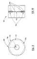
- Figures 1 to 3 depict the final drafting section 10 of a worsted spinning frame which is conventional to the extent that it includes a front pair of top 12 and bottom 13 drafting rollers defining a drafting nip 14 to which is fed a staple fibre assembly in the form of a drafted roving 8.
- the drafted assembly, yarn 9 is drawn onto a rotating take-up package 16 centred in a ring assembly 18.
- the yarn passes through a freely rotating traveller on the ring.
- the rotation of the package 16 causing the yarn to move the traveller around the ring, provides the means to insert twist into the yarn and wind it into the package.
- the ring spinner cyclically traverses the package 16 in the usual manner.
- roller 20 Mounted in driving contact with the top front drafting roller 12 is a splitting roller 20.
- Roller 20 is fitted in end-bearings (not shown), and includes two axially adjacent coaxial cylindrical lands 22, 23.
- the boundary between the two lands is an annular shoulder 24 which lies in a plane normal to the axis of roller 20.
- Larger diameter land 23 is in frictional drive contact with drafting roller 12.
- Shoulder 24 is positioned to be aligned approximately with the centre line of the fibre assembly 8a emerging from nip 14.
- the fibre assembly 8a is thereby split or divided into two distinct fibre sub-assemblies or strands 9a, 9b, which traverse different paths about cylindrical roller lands 22, 23 and then recombine at convergence point 30, where the strands are twisted together to form yarn 9.
- strands 9a, 9b are of different length: lower strand 9a traverses a shorter path and touches smaller-diameter roller land 22 over a shorter contact distance than in the case of upper strand 9b, in contact with land 23. It is observed that the twist travels back along upper strand 9b past convergence point 30 substantially only to the contact point 32 with roller land 23, whereas the twist in strand 9a travels back nearly to nip 14.
- these sections of the bridging fibres are wrapped or twisted around one or both strands at a different and probably higher helix angle than the twist which is propagating into the strands from the formed yarn. Hence, these fibres experience an enhanced form of fibre migration and entrapment.
- This wrapping effect both for fibres and for larger components of the yarn will result in differential unwrapping, or release of length, when the yarns are effectively untwisted in a plying operation.
- the result may enhance bulk.
- the action of splitting the emerging fibre strand narrows the individual ribbon widths of the sub-assemblies, affording better incorporation of the fibres at the outer edges of the fibre strand as it emerges from the nip 14 of the front drafting rollers.
- weavable singles yarns made in accordance with this embodiment of the invention can be as few as 50, or even less, fibres on average in cross-section.
- the tension differential during yarn formation may also result in enhanced yarn bulk when the yarns are plied.
- the splitting roller 20 depicted in the embodiment of Figures 1 to 3 requires centring with the travelling fibre assembly 8a emerging from the front drafting rollers 12, 13 and does not allow for strand traversing which is normal on standard spinning frames to minimise top roller wear.
- a 1 mm, full width land 40 may be incorporated to assist in resplitting the fibre assembly (Figure 4).
- Figures 5 and 6 show another alternative method of maintaining the split.
- the two cam-type surfaces 22', 23' induce the fibre assembly to split down the right then left side of the centre every half revolution of the splitting roller 20'.
- These surfaces 22',23' thus cause a cyclic alteration of the relative positions of the sub-assemblies 9a,9b.
- the strand splitting roller 20" shown in Figures 7 and 8 are designed to obviate the need to centre the roller and to allow for fibre strand traversal.
- Each groove (50) and land (52) pair act according to the same principle as the roller design in Figures 5 and 6.
- the groove and land widths on this roller are, for example, 1 mm, however, subsequent observation has shown that it may be beneficial to reduce these dimensions, ie a larger number of grooves and lands per unit width of the splitting roller, particularly when the fibre strand width is narrower, ie when the yarn being formed is finer.
- the frequency with which the fibre assembly is cyclically split from one side to the other may be increased from every half revolution of the splitting roller as described above, to every quarter revolution or less.
- Cam-type arrangements may possibly be dispensed with altogether if the groove and land widths are of the order of tens or hundreds of micrometres wide.
- the grooves and lands in the latter case may be manufactured from a series of discs of fixed or varying alternating diameters.
- the action of the multi-cam splitting roller 20" in Figures 7 and 8 is similar to that described above in connection with the simple splitting roller 20.
- the fibre assembly emergent from the drafting nip is observed to split quite frequently into three strands.
- One strand follows the longer path length with the other two following the shorter path lengths in the grooves.
- the assembly When spinning a finer yarn count, the assembly generally splits into two sections. Multiple strand splitting may offer improved fibre migration and entrapment with the use of narrower groove and land widths.
- the splitting rollers of Figures 5 and 7 are also effective to cyclically alter the relative path lengths traversed by the strands 9a, 9b, to alter their relative positions and to alter the length of strand into which twist may propagate, and thereby to cyclically alter the relative twist in the strands upstream of convergence point 30.
- Observation of a high speed video of the device in Figure 5 spinning two strands showed that, alternately, more twist was propagated into one strand and then into the other after each change over.
- the strand with the lower twist which was also the strand on the lower portion during each cycle, appeared to wrap around the strand with the higher twist. This mechanism appears to trap significant levels of strand twist in the individual strands.
- roller 120 has a configuration of grooves 150 arranged as alternating sections of single and double grooves 152,154 around the circumference.
- the grooves alternately change the positions of respective outer and central sections or fibre assemblies of an emerging fibre ribbon. Effective entrapment of a fibre within the yarn requires that a fibre experiences several trapping points along its length.
- the roller circumference is divided into six sections (three double groove sections alternating with three single groove sections), for example each of 15 mm to achieve approximately four points along an average fibre length of 60 mm at which the central sub-assembly is trapped between the other two.
- the dashed lines 156 in the side view of Figure 9 indicate how the grooves are cut into the roller attachments.
- the length of each cut in this case subtends 60° of arc, which in a typical and practical case is approximately equivalent to 15 mm of circumference.
- More complex false-braiding designs are also envisaged.
- the designs varying according to whether the fibre ribbon is deliberately split into three, four or more sub-assemblies.
- three sub-assemblies which will be referred to here for convenience as strands
- a variation may start with the two left-hand strands lowered, followed by raising the central strand (left-hand lowered, 2 right-hand raised), raising the left-hand strand and simultaneously lowering the right-hand strand (2 left-hand raised, right-hand lowered), finally lowering the central strand (left-hand raised, 2 right-hand lowered) before repeating.
- roller attachment shown in Figures 9 and 10 requires that the groove sections always be aligned with the emerging fibre ribbon. To even out the wear of the top drafting rollers, on most spinning frames the roving from which the fibre ribbons are drafted is slowly traversed sideways back and forth. It would be difficult, or at the least make the whole arrangement rather complex, to make the roller attachment traverse to maintain alignment with the roving. Therefore, to overcome alignment problems, in practice there may be a series of similar groove configurations along the width of the roller attachments, along the lines of that shown in Figure 8.
- the splitting roller 20 is depicted in Figures 1 to 3 in contact with the top drafting roller 12 of the spinning frame. This makes for easier observation of the yarn forming mechanism since it occurs at the front of the splitting roller. However it has been found that the same mechanism occurs when the splitting roller 21 is mounted on the bottom front drafting roller 13a, as shown in Figure 11. Repositioning the spinning frame suction tubes below the splitting rollers, when mounted as in Figures 1 and 2, allows piecing up to be easily carried out at spinning start-up or in the event of an end down. This indicates that piecing-up with the splitting rollers mounted against the bottom front drafting roller would also be readily achievable.
- the other embodiments may also alternatively be mounted on the bottom front drafting roller.
- Figure 12 depicts the final drafting section 210 of a worsted spinning frame which is conventional to the extent that it includes a front pair of top 212 and bottom 213 drafting rollers defining a drafting nip 214 to which is fed a staple fibre assembly in the form of a drafted roving or sliver 208.
- the drafted assembly, yarn 209 is drawn through a guide 217 onto a rotating take-up package 216 centred in a ring assembly 218.
- the yarn passes through a freely rotating traveller on the ring.
- the rotation of the package 216 causing the yarn to move the traveller around the ring, provides the means to insert twist into the yarn and wind it into the package.
- the ring spinner cyclically traverses the package 216 in the usual manner.
- roller 220 Mounted in driving contact with the bottom front drafting roller 213 is a patterned dividing and braiding roller 220.
- Roller 220 is fitted in end-bearings (not shown), and includes ( Figure 14) two helical grooves 222,223 of opposite hand.
- Groove 223 is of substantially greater width and depth than groove 223.
- the grooves are of similar helix angle, and intersect at two cross-overs 225 per revolution.
- the cross-sectional shape of the grooves although depicted as arcuate and uniform, is not critical.
- Roller 220 is effective to divide roving 208 into a plurality of fibre sub-assemblies, and to then cyclically vary the paths of these sub-assemblies, and their relative positions, by causing them to interbraid by cyclically laying the sub-assemblies back and forth over each other.
- the principle involved can be explained as follows, with reference to the diagrams of Figure 13. Approximating the fibre assembly 208 as a ribbon like structure, for intertwining/braiding, two components of movement are essential to interchange the position of groups or sub-assemblies of fibres in the ribbon.
- the crossed groove arrangement both naturally divides and spreads the fibre assembly laterally, and the different depths at the cross-over points forces intertwining/braiding of the resultant sub-assemblies. It has been observed that after some initial running, most of the fibre assembly is naturally split and situated in the grooves. Theoretically, during the first revolution, all positions across the incoming fibre "ribbon" assembly will have come in contact with a groove, and due to the geometry they will tend to fall into the groove. Once in the groove the fibre is "trapped” in the groove so that as rotation continues the remaining length of the fibre (and adjacent fibres) are pulled into the groove and thus move sideways with the groove. At the cross-over positions fibres will tend to remain in their existing groove and thus crossover/under a neighbouring group.
- a roller 230 can be attached as shown, driven by roller 220, to stabilise sideways slipping of the sub-assemblies. It will also be understood that roller 220 can alternatively be driven from the top front roller 212, in which case the geometry is slightly different with the yarn path being over the roller 220 rather than under it.
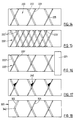
- FIG. 15 to 18 Other possible configurations of dividing and braiding roller are illustrated in Figures 15 to 18.
- a first alternative is the use of multiple left and right hand helical grooves.
- Figure 15 illustrates an example of a roller 220' with three start left and right hand grooves. Multiple grooves increase the frequency of crossovers per revolution of the roller and hence allow more interactions per unit length of yarn.
- each groove is at a constant depth. Interaction between sub-assemblies can be increased by altering the depth along a groove so that for example it alternates deep then shallow between successive crossover points. In the simple case of one groove of each hand, ie only two crossovers per revolution, this cyclic depth variation can be readily achieved by cutting at least one of the grooves eccentrically to the axis of the roller.
- roller design as shown in Figure 16 can be advantageous.
- the roller 220" is driven from the pre-existing front roller of the spinning apparatus by the slightly larger diameter land 221 at one end. This generates a small degree of overfeeding of the incoming sliver onto the grooved roller. This has been unexpectedly found to allow significantly more lateral movement of each sub-assembly (and hence more interactions with other sub-assemblies) before the lateral tension builds up and forces the sub-assembly to jump out into a neighbouring groove moving in the opposition direction.
- the cross-over design in Figure 17 is very similar to that commonly used in yarn package winding machines and illustrated at 320 in Figure 18. Although these designs were developed for feeding a single yarn it has been unexpectedly found that these designs split the fibre assembly and confer a regular braiding pattern to the fibre assembly when utilised as the roller 220 in the apparatus of Figure 12. Further, at the extremities of the roller, the groove 322 deliberately changes the direction of travel of the fibre group (eg at bend 342) whereas in previous examples this change in direction relies on the tension of the extremities forcing the group into the opposite groove.
- An example of a three-way divided braided structure produced by the roller of Figure 18 is depicted in simple diagrammatic form in Figure 19.
- the braiding technique described above with reference to Figures 12 to 19 is effective to cause enhanced intermingling of fibres of the overlaid sub-assemblies, and therefore of the fibres in the final spun yarn 209.
- a useful level of yarn strength and/or abrasion resistance, relative to the average number of fibres in the yarn cross-section, is achieved
Claims (37)
- Vorrichtung zum Spinnen von Garn mit:dadurch gekennzeichnet, daß die Vorrichtung ferner umfaßt:Streck- bzw. Verziehmitteln (12, 13) zum Empfangen und zum Strecken bzw. Verziehen einer durchlaufenden Faseranordnung, undeinem Aufnahmemittel (16) zum Ziehen und Aufnehmen der Faseranordnung von dem Streckmittel,ein Mittel (20), um die durchlaufende Faseranordnung in mehrere Faser-Unteranordnungen stromabwärts von dem Streckmittel zu unterteilen und zu veranlassen, daß die Unteranordnungen verschiedene Bahnen durchlaufen, undMittel (16, 18) zum Rekombinieren der Faser-Unteranordnungen, um durch Zusammendrehen der Unteranordnungen das Garn zu bilden,ferner dadurch gekennzeichnet, daß die Bahnen genügend nahe aneinander liegen, damit Fasern von einer oder mehreren der Unteranordnungen kontinuierlich übertragen und auf oder in eine andere oder andere Unteranordnung(en) gezogen werden.
- Vorrichtung gemäß Anspruch 1, ferner dadurch gekennzeichnet, daß das Rekombiniermittel wirksam ist, die Unteranordnungen so zusammenzudrehen, daß die Verdrehung längs der einen der Faser-Unteranordnungen am Rekombinationspunkt vorbei weiter zurückwandert als bei einer anderen Faser-Unteranordnung.
- Vorrichtung gemäß Anspruch 1 oder 2, ferner dadurch gekennzeichnet, daß die Mittel zum Unterteilen und Rekombinieren derart (gestaltet) sind, daß die Faser-Unteranordnungen verschiedene Bahnlängen haben, durch welche zwischen Unteranordnungen übertragene Fasern verschiedene axiale Spannungen aufweisen.
- Vorrichtung gemäß einem der vorangehenden Ansprüche, ferner dadurch gekennzeichnet, daß das Mittel zum Unterteilen der durchlaufenden Faseranordnung eine drehbare Rollenstruktur (20) mit betreffenden Stegen (22, 23) verschiedener Versetzungen und/oder Radien bezüglich einer Drehachse aufweist.
- Vorrichtung gemäß Anspruch 4, ferner dadurch gekennzeichnet, daß die drehbare Rollenstruktur so angeordnet ist, daß sie eine zyklische Veränderung der von den Unteranordnungen durchlaufenen Bahnlängen bewirkt.
- Verfahren zum Spinnen eines Garns, umfassend das Empfangen und Strecken bzw. Verziehen einer anfänglich durchlaufenden Faseranordnung, und das Ziehen und Aufnehmen der Faseranordnung, dadurch gekennzeichnet, daß die anfänglich durchlaufende Faseranordnung in mehrere Faser-Unteranordnungen unterteilt wird, daß die Unteranordnungen veranlaßt werden, verschiedene Bahnen zu durchlaufen, und diese dann durch Zusammendrehen der Unteranordnungen rekombiniert werden, wobei die Bahnen genügend nahe aneinanderliegen, damit Fasern von einer oder mehreren der Unteranordnungen kontinuierlich übertragen und auf oder in eine andere oder andere Unteranordnung(en) gezogen werden.
- Verfahren gemäß Anspruch 6, ferner dadurch gekennzeichnet, daß die Verdrehung längs der einen der Faser-Unteranordnungen am Rekombinationspunkt vorbei weiter zurückwandert als bei einer anderen Faser-Unteranordnung.
- Verfahren gemäß Anspruch 6 oder 7, ferner dadurch gekennzeichnet, daß die Faser-Unteranordnungen verschiedene Bahnlängen haben, durch die die zwischen Unteranordnungen übertragenen Fasern verschiedene axiale Spannungen haben.
- Verfahren gemäß einem der Ansprüche 6 bis 8, ferner dadurch gekennzeichnet, daß die von den Unteranordnungen durchlaufenen Bahnlängen zyklisch verändert werden.
- Verfahren gemäß einem der Ansprüche 6 bis 9, ferner dadurch gekennzeichnet, daß die Faseranordnungen natürliche oder vom Menschen gefertigte Stapel-Faseranordnungen sind.
- Vorrichtung zum Spinnen von Garn mit:dadurch gekennzeichnet, daß die Vorrichtung ferner umfaßt:Streck- bzw. Verziehmitteln (12, 13) zum Empfangen und zum Strecken bzw. Verziehen einer durchlaufenden Faseranordnung, undeinem Aufnahmemittel (16) zum Ziehen und Aufnehmen der Faseranordnung von den Streckmitteln,ein Mittel (20), um die durchlaufende Faseranordnung in mehrere Faser-Unteranordnungen stromabwärts von den Streckmitteln zu unterteilen,ein Mittel (20), um zu bewirken, daß die Unteranordnungen zyklisch variierende Bahnen durchlaufen, undMittel (16, 18) zum Rekombinieren der Faser-Unteranordnungen, um durch Zusammendrehen der Unteranordnungen ein Garn zu bilden.
- Vorrichtung gemäß Anspruch 11, dadurch gekennzeichnet, daß das Mittel zum Unterteilen der durchlaufenden Faseranordnung eine drehbare Rollenstruktur (20) mit betreffenden Stegen (22,23) verschiedener Versetzungen und/oder Radien bezüglich einer Drehachse aufweist.
- Vorrichtung gemäß Anspruch 11 oder 12, ferner dadurch gekennzeichnet, daß das Mittel, um zu veranlassen, daß die Unteranordnungen variierende Bahnen durchlaufen, ein Flechtmittel (120) zum zyklischen Austausch der relativen Lateralpositionen der Unteranordnungen aufweist.
- Vorrichtung gemäß Anspruch 13, ferner dadurch gekennzeichnet, daß das Flechtmittel wirksam ist, jede Unteranordnung über eine andere Unteranordnung zu legen und dann die erstere in ihre ursprüngliche relative Lateralposition zurückzuführen.
- Vorrichtung gemäß Anspruch 13 oder 14, ferner dadurch gekennzeichnet, daß das Flechtmittel wirksam ist, das Verzwirbeln von Fasern zwischen den Unteranordnungen zu verbessern.
- Vorrichtung gemäß einem der Ansprüchen 13 bis 15, ferner dadurch gekennzeichnet, daß das Flechtmittel wirksam ist, vor der Einführung einer Verdrehung ein verflochtenes Fasernetz zu erzeugen.
- Vorrichtung gemäß einem der Ansprüche 13 bis 16, ferner dadurch gekennzeichnet, daß das Flechtmittel auch als das Mittel zum Unterteilen der durchlaufenden Faseranordnung in die mehreren Unteranordnungen dient.
- Vorrichtung gemäß Anspruch 17, ferner dadurch gekennzeichnet, daß das Flechtmittel eine drehbare Rollenstruktur (120) mit betreffenden unterschiedlichen Schrauben- bzw. Spiral- oder Schneckenrillen (152, 154) aufweist, um die zyklische Veränderung der von den Unteranordnungen durchlaufenen Bahnen und/oder ihrer Relativpositionen zu bewerkstelligen.
- Verfahren zum Spinnen eines Garns, umfassend das Empfangen und Strecken bzw. Verziehen einer anfänglich durchlaufenden Faseranordnung, und das Ziehen und Aufnehmen der Faseranordnung, dadurch gekennzeichnet, daß die anfänglich durchlaufende Faseranordnung in mehrere Faser-Unteranordnungen unterteilt wird, daß die mehreren Unteranordnungen veranlaßt werden, zyklisch variierende Bahnen zu durchlaufen, und dann rekombiniert werden, um durch Zusammendrehen der Unteranordnungen ein Garn zu bilden.
- Verfahren gemäß Anspruch 19, ferner dadurch gekennzeichnet, daß die von den Unteranordnungen durchlaufenen Bahnenlängen zyklisch verändert werden.
- Verfahren gemäß Anspruch 19 oder 20, ferner dadurch gekennzeichnet, daß die Bahnen der Unteranordnungen verändert werden, indem die relativen Lateralpositionen der Unteranordnungen zyklisch gegeneinander vertauscht werden, um eine Geflechtstruktur zu bilden.
- Verfahren gemäß Anspruch 21, ferner dadurch gekennzeichnet, daß jede Unteranordnung über eine andere Unteranordnung gelegt und dann in ihre ursprüngliche relative Lateralposition zurückgeführt wird.
- Verfahren gemäß Anspruch 21 oder 22, ferner dadurch gekennzeichnet, daß die Verflechtung gemäß einer vorbestimmten Sequenz längs der Länge der sich bewegenden Faseranordnung, die zur Optimierung von Faser-Interaktionen gewählt wird, gesteuert wird.
- Verfahren gemäß Anspruch 21, 22 oder 23, ferner dadurch gekennzeichnet, daß die Verflechtung wirksam ist, vor der Einführung einer Verdrehung ein ineinander verflochtenes Fasernetz zu erzeugen.
- Vorrichtung zum Spinnen eines Stapelgarns mit:dadurch gekennzeichnet, daß die Vorrichtung ferner umfaßt:Streck- bzw. Verziehmitteln (12, 13) zum Empfangen und zum Strecken bzw. Verziehen einer durchlaufenden Stapel-Faseranordnung, undeinem Aufnahmemittel (16) zum Ziehen und Aufnehmen der Faseranordnung von den Streckmitteln,ein Mittel (20), um die durchlaufende Faseranordnung stromabwärts von den Streckmitteln in mehrere Faser-Unteranordnungen zu unterteilen, undVerdrehungsmittel (16,18), um die Unteranordnungen zusammenzudrehen, um das Garn zu bilden, undMittel (22,23), um die Relativpositionen der Unteranordnungen zwischen ihrer Unterteilung von der Faseranordnung und ihrem Zusammendrehen zyklisch zu verändern.
- Vorrichtung gemäß Anspruch 25, ferner dadurch gekennzeichnet, daß das Mittel zum Unterteilen der durchlaufenden Faseranordnung eine drehbare Rollenstruktur (20) mit betreffenden Stegen (22,23) verschiedener Versetzungen und/oder Radien bezüglich einer Drehachse aufweist.
- Verfahren zum Spinnen eines Garns, umfassend das Empfangen und Strecken bzw. Verziehen einer anfänglich durchlaufenden Faseranordnung, und das Ziehen und Aufnehmen der Faseranordnung, dadurch gekennzeichnet, daß die anfänglich durchlaufende Faseranordnung in mehrere Faser-Unteranordnungen unterteilt wird, das Garn durch Zusammendrehen der Unteranordnungen gebildet wird und daß es (das Verfahren) ferner das zyklische Verändern der Relativpositionen der Unteranordnungen zwischen ihrer Unterteilung von der Faseranordnung und ihrem Zusammendrehen umfaßt.
- Verfahren gemäß Anspruch 27, ferner dadurch gekennzeichnet, daß die von den Unteranordnungen durchlaufenen Bahnlängen zyklisch variiert werden.
- Verfahren zum Bilden eines Garns, umfassend das Empfangen und Strecken bzw. Verziehen einer anfänglich durchlaufenden Faseranordnung, und das Ziehen und Aufnehmen der Faseranordnung, dadurch gekennzeichnet, daß die anfänglich durchlaufende Faseranordnung in mehrere Faser-Unteranordnungen unterteilt wird, die Faser-Unteranordnungen an einem Konvergenzpunkt zusammengedreht werden, um ein Garn zu bilden, und (das Verfahren) ferner das zyklische Verändern der relativen Fortpflanzung der Verdrehung in den und/oder in die Unteranordnungen stromaufwärts vom Konvergenzpunkt umfaßt.
- Verfahren gemäß Anspruch 29, wobei die Veränderung der relativen Fortpflanzung der Verdrehungen durch zyklisches Verändern eines oder mehrerer der folgenden Faktoren bewirkt wird: des Abstands zwischen dem letzten Oberflächenkontakt oder Berührungspunkt der Unteranordnungen und ihrer Konvergenz bzw. ihrem Konvergenzpunkt, der Relativpositionen der Unteranordnungen sowie der Bahnlänge der Unteranordnungen vor ihrer Konvergenz.
- Vorrichtung zum Bilden eines Garns mit:dadurch gekennzeichnet, daß die Vorrichtung ferner umfaßt:Streck- bzw. Verziehmitteln (12,13) zum Empfangen und zum Strecken bzw. Verziehen einer durchlaufenden Faseranordnung, undeinem Aufnahmemittel (16) zum Ziehen und Aufnehmen der Faseranordnung von den Streckmitteln,ein Mittel (20), um die durchlaufende Faseranordnung in mehrere Faser-Unteranordnungen stromabwärts von den Streckmitteln zu unterteilen, undMittel (18,18) zum Zusammendrehen der Faser-Unteranordnungen an einem Konvergenzpunkt (30), um ein Garn zu bilden, und sie (die Vorrichtung) Mittel (22,23) zum zyklischen Verändern der relativen Fortpflanzung der Verdrehung in den und/oder in die Unteranordnungen stromaufwärts vom Konvergenzpunkt aufweist.
- Vorrichtung gemäß Anspruch 31, ferner dadurch gekennzeichnet, daß die Mittel zum Variieren der Veränderung der relativen Fortpflanzung der Verdrehung ein Mittel zum zyklischen Verändern eines oder mehrerer der folgenden Faktoren aufweist: des Abstands zwischen dem letzten Oberflächenkontakt oder Berührungspunkt der Unteranordnungen und ihrer Konvergenz bzw. ihrem Konvergenzpunkt, der Relativpositionen der Unteranordnungen sowie der Bahnlänge der Unteranordnungen vor ihrer Konvergenz.
- Vorrichtung gemäß Anspruch 31 oder 32, ferner dadurch gekennzeichnet, daß das Mittel zum Variieren der relativen Fortpflanzung der Verdrehung eine drehbare Rollenstruktur mit betreffenden Stegen verschiedener Versetzungen und/oder Radien bezüglich einer Drehachse aufweist.
- Verfahren gemäß einem der Ansprüche 19, 27 oder 29, ferner dadurch gekennzeichnet, daß drei oder mehr Faser-Unteranordnungen vorhanden sind, und die relative Fortpflanzung der Verdrehung oder die relativen Bahnen so variiert werden, daß sie eine Garnstruktur erzeugen, bei der jede Faser-Unteranordnung zwischen weiteren zwei der Faser-Unteranordnungen mit beabstandeten Intervallen entlang dem Garn festgehalten wird.
- Vorrichtung gemäß einem der Ansprüche 11, 26 oder 31, ferner dadurch gekennzeichnet, daß drei oder mehr Faser-Unteranordnungen vorhanden sind, und die relative Fortpflanzung der Verdrehung oder die relative Bahn so variiert wird, daß eine Garnstruktur erzeugt wird, bei der jede Faser-Unteranordnung zwischen weiteren zwei der Faser-Unteranordnungen mit beabstandeten Intervallen entlang dem Garn festgehalten wird.
- Verfahren gemäß einem der Ansprüche 19 bis 24, 27 bis 30 und 34, ferner dadurch gekennzeichnet, daß die Faseranordnungen natürliche oder vom Menschen gefertigte Stapel-Faseranordnungen sind.
- Verfahren gemäß Anspruch 36, ferner dadurch gekennzeichnet, daß die Faseranordnungen Wolle sind.
Applications Claiming Priority (10)
| Application Number | Priority Date | Filing Date | Title |
|---|---|---|---|
| AUPM260493 | 1993-11-23 | ||
| AUPM2604/93 | 1993-11-23 | ||
| AUPM260493 | 1993-11-23 | ||
| AUPM7771A AUPM777194A0 (en) | 1994-08-30 | 1994-08-30 | Yarn spinning |
| AUPM7771/94 | 1994-08-30 | ||
| AUPM777194 | 1994-08-30 | ||
| AUPM8987/94 | 1994-10-24 | ||
| AUPM8987A AUPM898794A0 (en) | 1994-10-24 | 1994-10-24 | Textile processing by braiding |
| AUPM898794 | 1994-10-24 | ||
| PCT/AU1994/000719 WO1995014800A1 (en) | 1993-11-23 | 1994-11-22 | Yarn spinning |
Publications (3)
| Publication Number | Publication Date |
|---|---|
| EP0746643A1 EP0746643A1 (de) | 1996-12-11 |
| EP0746643A4 EP0746643A4 (de) | 1996-12-27 |
| EP0746643B1 true EP0746643B1 (de) | 2002-03-27 |
Family
ID=27157753
Family Applications (1)
| Application Number | Title | Priority Date | Filing Date |
|---|---|---|---|
| EP95901276A Expired - Lifetime EP0746643B1 (de) | 1993-11-23 | 1994-11-22 | Fadenspinnen |
Country Status (16)
| Country | Link |
|---|---|
| US (1) | US6012277A (de) |
| EP (1) | EP0746643B1 (de) |
| JP (1) | JP3670283B2 (de) |
| KR (1) | KR100353672B1 (de) |
| CN (1) | CN1050395C (de) |
| AT (1) | ATE215136T1 (de) |
| BR (1) | BR9408126A (de) |
| CZ (1) | CZ287519B6 (de) |
| DE (1) | DE69430267D1 (de) |
| ES (1) | ES2174914T3 (de) |
| IN (1) | IN182507B (de) |
| NZ (1) | NZ276337A (de) |
| PL (1) | PL175807B1 (de) |
| PT (1) | PT746643E (de) |
| SK (1) | SK67196A3 (de) |
| WO (1) | WO1995014800A1 (de) |
Families Citing this family (25)
| Publication number | Priority date | Publication date | Assignee | Title |
|---|---|---|---|---|
| CN100425748C (zh) * | 2002-04-24 | 2008-10-15 | 香港理工大学 | 单股无扭矩环锭纱线的加工方法与设备 |
| JP2008502378A (ja) | 2004-05-25 | 2008-01-31 | チェストナット メディカル テクノロジーズ インコーポレイテッド | フレキシブルな血管閉鎖デバイス |
| KR101300437B1 (ko) | 2004-05-25 | 2013-08-26 | 코비디엔 엘피 | 동맥류용 혈관 스텐트 |
| US8628564B2 (en) | 2004-05-25 | 2014-01-14 | Covidien Lp | Methods and apparatus for luminal stenting |
| US8617234B2 (en) * | 2004-05-25 | 2013-12-31 | Covidien Lp | Flexible vascular occluding device |
| US20060206200A1 (en) * | 2004-05-25 | 2006-09-14 | Chestnut Medical Technologies, Inc. | Flexible vascular occluding device |
| US7096655B2 (en) * | 2004-06-02 | 2006-08-29 | The Hong Kong Polytechnic University | Method and apparatus for manufacturing a singles ring yarn |
| US8850784B2 (en) * | 2005-11-16 | 2014-10-07 | Lorica International Corporation | Fire retardant compositions and methods and apparatuses for making the same |
| US8152833B2 (en) | 2006-02-22 | 2012-04-10 | Tyco Healthcare Group Lp | Embolic protection systems having radiopaque filter mesh |
| US7513021B1 (en) * | 2008-02-28 | 2009-04-07 | Haselwander John G | Variable coring of twisted yarn |
| TR201000167A2 (tr) * | 2010-01-11 | 2011-05-23 | Özdi̇lek Ev Teksti̇l Sanayi̇ Ve Ti̇caret Anoni̇m Şi̇rketi̇ | Çok damarlı tek kat iplik üretim sistemi. |
| US8616110B2 (en) * | 2010-09-01 | 2013-12-31 | Ford Global Technologies, Llc | Method and apparatus for making a fiber reinforced article |
| CN102108571B (zh) * | 2010-12-09 | 2013-03-20 | 安徽华茂纺织股份有限公司 | 细纱绕皮辊接头操作方法 |
| CN102747488B (zh) * | 2012-06-26 | 2014-10-15 | 东华大学 | 双辊差动式二级分劈展纱器、纺纱方法及其应用 |
| CN102747489B (zh) * | 2012-06-26 | 2014-10-15 | 东华大学 | 双张力盘阻尼差动二级分劈展纱器、纺纱方法及其应用 |
| US9114001B2 (en) | 2012-10-30 | 2015-08-25 | Covidien Lp | Systems for attaining a predetermined porosity of a vascular device |
| US9452070B2 (en) | 2012-10-31 | 2016-09-27 | Covidien Lp | Methods and systems for increasing a density of a region of a vascular device |
| US9943427B2 (en) | 2012-11-06 | 2018-04-17 | Covidien Lp | Shaped occluding devices and methods of using the same |
| US9157174B2 (en) | 2013-02-05 | 2015-10-13 | Covidien Lp | Vascular device for aneurysm treatment and providing blood flow into a perforator vessel |
| CN108456956A (zh) | 2017-02-17 | 2018-08-28 | 香港纺织及成衣研发中心有限公司 | 一种用于环锭细纱机的纱线加捻方法和装置 |
| US11065009B2 (en) | 2018-02-08 | 2021-07-20 | Covidien Lp | Vascular expandable devices |
| US11065136B2 (en) | 2018-02-08 | 2021-07-20 | Covidien Lp | Vascular expandable devices |
| CN109537121A (zh) * | 2019-01-23 | 2019-03-29 | 上海海事大学 | 自动捻线装置 |
| EP3725923A1 (de) * | 2019-04-16 | 2020-10-21 | Calik Denim Tekstil San. Ve Tic. A.S. | Verbundgarn, gewebe mit dem verbundgarn, verfahren zur herstellung eines verbundgarns und anordnung zur herstellung eines verbundgarns |
| KR102470687B1 (ko) | 2021-07-01 | 2022-11-23 | 한국섬유개발연구원 | 촉감과 물성 향상을 위한 이종 단섬유를 갖는 트윈구조 방적사 및 이의 제조 방법 |
Family Cites Families (20)
| Publication number | Priority date | Publication date | Assignee | Title |
|---|---|---|---|---|
| US2358656A (en) * | 1942-12-22 | 1944-09-19 | Goodall Worsted Company | Method of spinning single ply yarn composed of both relatively long and relatively short fibers |
| US2925628A (en) * | 1955-04-25 | 1960-02-23 | Bancroft Brillotex Internat S | Machine for separating wool fibres or other filaments |
| GB987982A (en) * | 1961-02-28 | 1965-03-31 | Mackie & Sons Ltd J | Improvements relating to textile drafting apparatus |
| US3599416A (en) * | 1969-06-09 | 1971-08-17 | Ver Volkseigener Betriebebaumw | Method of and apparatus for spinning, doubling and twisting |
| GB1413963A (en) * | 1972-01-14 | 1975-11-12 | Platt Saco Lowell Ltd | Manufacture of multi-fold yarns |
| DE2353805A1 (de) * | 1973-10-26 | 1975-05-15 | Gerrit Van Delden & Co | Vorrichtung zur herstellung von flammengarn |
| CA1024837A (en) * | 1974-06-11 | 1978-01-24 | Robert J. Clarkson | Method and apparatus for producing a piled yarn |
| FR2404589A1 (fr) * | 1977-10-03 | 1979-04-27 | Rhone Poulenc Textile | Procede et dispositif de transfert de fil textile |
| JPS5930811B2 (ja) * | 1980-07-25 | 1984-07-28 | 和久 原川 | 糸断面の内.外層に異種繊維を配置させた紡績糸の製造法 |
| FR2508939A1 (fr) * | 1981-07-02 | 1983-01-07 | Saint Andre Filature | Cylindre entaille, pour machines de filature-retordage sur broche tubulaire et machines, notamment pour la fabrication de fils fantaisie, en comportant l'utilisation |
| SU1142539A1 (ru) * | 1984-03-30 | 1985-02-28 | Центральный научно-исследовательский институт промышленности лубяных волокон | Приспособление дл присучивани оборвавшейс мычки к другой мычке на пр дильной машине дл однопроцессного получени крученой пр жи |
| SU1286646A1 (ru) * | 1985-02-22 | 1987-01-30 | Ленинградский институт текстильной и легкой промышленности им.С.М.Кирова | Однозонный выт жной прибор текстильной машины |
| US4662164A (en) * | 1985-12-26 | 1987-05-05 | Burlington Industries, Inc. | Separation, and phasing of sheath sliver around a core |
| CH681897A5 (de) * | 1989-07-31 | 1993-06-15 | Rieter Ag Maschf | |
| DE3927739A1 (de) * | 1989-08-23 | 1991-02-28 | Fritz Stahlecker | Verfahren und vorrichtung zum falschdrallspinnen |
| DE3933218A1 (de) * | 1989-10-05 | 1991-04-18 | Schlafhorst & Co W | Faserbandteiler |
| US5228281A (en) * | 1989-11-04 | 1993-07-20 | Fritz Stahlecker | Arrangement and method for false-twist spinning |
| JPH04153329A (ja) * | 1990-10-11 | 1992-05-26 | Hara Shiyokuki Seisakusho:Kk | トップローラ |
| RU2106438C1 (ru) * | 1992-07-14 | 1998-03-10 | Вул Рисерч Организэйшн оф Нью Зиланд Инк. | Пряжа (варианты), способ ее изготовления (варианты) и устройство для его осуществления (варианты) |
| AT398086B (de) * | 1993-02-15 | 1994-09-26 | Fehrer Ernst | Streckwerk für eine ringspinnvorrichtung |
-
1994
- 1994-11-22 BR BR9408126A patent/BR9408126A/pt not_active Application Discontinuation
- 1994-11-22 PL PL94314607A patent/PL175807B1/pl not_active IP Right Cessation
- 1994-11-22 NZ NZ276337A patent/NZ276337A/en unknown
- 1994-11-22 AT AT95901276T patent/ATE215136T1/de not_active IP Right Cessation
- 1994-11-22 SK SK671-96A patent/SK67196A3/sk unknown
- 1994-11-22 US US08/647,971 patent/US6012277A/en not_active Expired - Fee Related
- 1994-11-22 PT PT95901276T patent/PT746643E/pt unknown
- 1994-11-22 KR KR1019960702732A patent/KR100353672B1/ko not_active IP Right Cessation
- 1994-11-22 EP EP95901276A patent/EP0746643B1/de not_active Expired - Lifetime
- 1994-11-22 DE DE69430267T patent/DE69430267D1/de not_active Expired - Lifetime
- 1994-11-22 JP JP51469495A patent/JP3670283B2/ja not_active Expired - Fee Related
- 1994-11-22 WO PCT/AU1994/000719 patent/WO1995014800A1/en active IP Right Grant
- 1994-11-22 ES ES95901276T patent/ES2174914T3/es not_active Expired - Lifetime
- 1994-11-22 CN CN94194628A patent/CN1050395C/zh not_active Expired - Fee Related
- 1994-11-22 IN IN369CA1994 patent/IN182507B/en unknown
- 1994-11-22 CZ CZ19961484A patent/CZ287519B6/cs not_active IP Right Cessation
Also Published As
| Publication number | Publication date |
|---|---|
| SK67196A3 (en) | 1997-03-05 |
| PL314607A1 (en) | 1996-09-16 |
| US6012277A (en) | 2000-01-11 |
| AU1058795A (en) | 1995-06-13 |
| JPH09505362A (ja) | 1997-05-27 |
| CZ148496A3 (en) | 1997-02-12 |
| EP0746643A1 (de) | 1996-12-11 |
| PT746643E (pt) | 2002-09-30 |
| PL175807B1 (pl) | 1999-02-26 |
| CN1139461A (zh) | 1997-01-01 |
| IN182507B (de) | 1999-04-24 |
| CZ287519B6 (en) | 2000-12-13 |
| ATE215136T1 (de) | 2002-04-15 |
| KR100353672B1 (ko) | 2003-02-11 |
| EP0746643A4 (de) | 1996-12-27 |
| AU688423B2 (en) | 1998-03-12 |
| NZ276337A (en) | 1996-12-20 |
| DE69430267D1 (de) | 2002-05-02 |
| WO1995014800A1 (en) | 1995-06-01 |
| CN1050395C (zh) | 2000-03-15 |
| JP3670283B2 (ja) | 2005-07-13 |
| ES2174914T3 (es) | 2002-11-16 |
| BR9408126A (pt) | 1997-08-05 |
Similar Documents
| Publication | Publication Date | Title |
|---|---|---|
| EP0746643B1 (de) | Fadenspinnen | |
| US4069656A (en) | Composite spun yarn and process for producing the same | |
| US8429889B2 (en) | Apparatus and method for producing a yarn | |
| US3394538A (en) | Spun yarn | |
| AU688423C (en) | Yarn spinning | |
| US6945026B1 (en) | Fibre yarn and rope production | |
| CN114214761B (zh) | 一种纺制短纤维皮芯结构纱线的纺纱装置 | |
| US3488939A (en) | Twisted thread assemblies | |
| JPS60110930A (ja) | 特殊意匠糸の製法 | |
| US5848524A (en) | Manufacture of yarn spun on closed-end, high draft spinning systems | |
| Kwasniak et al. | The formation and structure of fancy yarns produced by a pressurized-air method | |
| US5802826A (en) | Production of core/wrap yarns by airjet and friction spinning in tandem | |
| US3456434A (en) | Spun yarn | |
| Rengasamy | Fundamental principles of ring spinning of yarns | |
| JPS5930811B2 (ja) | 糸断面の内.外層に異種繊維を配置させた紡績糸の製造法 | |
| JP3095230B2 (ja) | 仮撚紡績方法と該方法を実施するための装置 | |
| JPH0120254B2 (de) | ||
| JPS61174438A (ja) | スラブヤ−ン及びその製造方法 | |
| JPH08158171A (ja) | クローズドエンド・ハイドラフト紡糸システムで紡糸される糸の製造の改良 | |
| Mahmoudi | Self-twist spinning | |
| JPS5911695B2 (ja) | 複合紡績糸およびその製造法 | |
| JPS5847483B2 (ja) | スラブ糸の製造方法 | |
| JPS58126322A (ja) | 芯鞘糸の製造方法 | |
| JPS5950766B2 (ja) | 特殊加工糸の製造方法 | |
| JPH0157168B2 (de) |
Legal Events
| Date | Code | Title | Description |
|---|---|---|---|
| PUAI | Public reference made under article 153(3) epc to a published international application that has entered the european phase |
Free format text: ORIGINAL CODE: 0009012 |
|
| 17P | Request for examination filed |
Effective date: 19960528 |
|
| AK | Designated contracting states |
Kind code of ref document: A1 Designated state(s): AT BE CH DE ES FR GB GR IE IT LI NL PT |
|
| AX | Request for extension of the european patent |
Free format text: SI PAYMENT 960528 |
|
| A4 | Supplementary search report drawn up and despatched |
Effective date: 19961113 |
|
| AK | Designated contracting states |
Kind code of ref document: A4 Designated state(s): AT BE CH DE ES FR GB GR IE IT LI NL PT |
|
| 17Q | First examination report despatched |
Effective date: 19981012 |
|
| GRAG | Despatch of communication of intention to grant |
Free format text: ORIGINAL CODE: EPIDOS AGRA |
|
| GRAG | Despatch of communication of intention to grant |
Free format text: ORIGINAL CODE: EPIDOS AGRA |
|
| GRAH | Despatch of communication of intention to grant a patent |
Free format text: ORIGINAL CODE: EPIDOS IGRA |
|
| GRAH | Despatch of communication of intention to grant a patent |
Free format text: ORIGINAL CODE: EPIDOS IGRA |
|
| REG | Reference to a national code |
Ref country code: GB Ref legal event code: IF02 |
|
| GRAA | (expected) grant |
Free format text: ORIGINAL CODE: 0009210 |
|
| AK | Designated contracting states |
Kind code of ref document: B1 Designated state(s): AT BE CH DE ES FR GB GR IE IT LI NL PT |
|
| AX | Request for extension of the european patent |
Free format text: SI PAYMENT 19960528 |
|
| PG25 | Lapsed in a contracting state [announced via postgrant information from national office to epo] |
Ref country code: NL Free format text: LAPSE BECAUSE OF FAILURE TO SUBMIT A TRANSLATION OF THE DESCRIPTION OR TO PAY THE FEE WITHIN THE PRESCRIBED TIME-LIMIT Effective date: 20020327 Ref country code: LI Free format text: LAPSE BECAUSE OF FAILURE TO SUBMIT A TRANSLATION OF THE DESCRIPTION OR TO PAY THE FEE WITHIN THE PRESCRIBED TIME-LIMIT Effective date: 20020327 Ref country code: GR Free format text: LAPSE BECAUSE OF FAILURE TO SUBMIT A TRANSLATION OF THE DESCRIPTION OR TO PAY THE FEE WITHIN THE PRESCRIBED TIME-LIMIT Effective date: 20020327 Ref country code: CH Free format text: LAPSE BECAUSE OF FAILURE TO SUBMIT A TRANSLATION OF THE DESCRIPTION OR TO PAY THE FEE WITHIN THE PRESCRIBED TIME-LIMIT Effective date: 20020327 Ref country code: BE Free format text: LAPSE BECAUSE OF FAILURE TO SUBMIT A TRANSLATION OF THE DESCRIPTION OR TO PAY THE FEE WITHIN THE PRESCRIBED TIME-LIMIT Effective date: 20020327 Ref country code: AT Free format text: LAPSE BECAUSE OF FAILURE TO SUBMIT A TRANSLATION OF THE DESCRIPTION OR TO PAY THE FEE WITHIN THE PRESCRIBED TIME-LIMIT Effective date: 20020327 |
|
| REF | Corresponds to: |
Ref document number: 215136 Country of ref document: AT Date of ref document: 20020415 Kind code of ref document: T |
|
| REG | Reference to a national code |
Ref country code: CH Ref legal event code: EP |
|
| REF | Corresponds to: |
Ref document number: 69430267 Country of ref document: DE Date of ref document: 20020502 |
|
| REG | Reference to a national code |
Ref country code: IE Ref legal event code: FG4D |
|
| PG25 | Lapsed in a contracting state [announced via postgrant information from national office to epo] |
Ref country code: DE Free format text: LAPSE BECAUSE OF FAILURE TO SUBMIT A TRANSLATION OF THE DESCRIPTION OR TO PAY THE FEE WITHIN THE PRESCRIBED TIME-LIMIT Effective date: 20020628 |
|
| ET | Fr: translation filed | ||
| NLV1 | Nl: lapsed or annulled due to failure to fulfill the requirements of art. 29p and 29m of the patents act | ||
| REG | Reference to a national code |
Ref country code: PT Ref legal event code: SC4A Free format text: AVAILABILITY OF NATIONAL TRANSLATION Effective date: 20020625 Ref country code: CH Ref legal event code: PL |
|
| PGFP | Annual fee paid to national office [announced via postgrant information from national office to epo] |
Ref country code: FR Payment date: 20021108 Year of fee payment: 9 |
|
| REG | Reference to a national code |
Ref country code: ES Ref legal event code: FG2A Ref document number: 2174914 Country of ref document: ES Kind code of ref document: T3 |
|
| PGFP | Annual fee paid to national office [announced via postgrant information from national office to epo] |
Ref country code: GB Payment date: 20021120 Year of fee payment: 9 |
|
| PG25 | Lapsed in a contracting state [announced via postgrant information from national office to epo] |
Ref country code: IE Free format text: LAPSE BECAUSE OF NON-PAYMENT OF DUE FEES Effective date: 20021122 |
|
| PLBE | No opposition filed within time limit |
Free format text: ORIGINAL CODE: 0009261 |
|
| STAA | Information on the status of an ep patent application or granted ep patent |
Free format text: STATUS: NO OPPOSITION FILED WITHIN TIME LIMIT |
|
| 26N | No opposition filed |
Effective date: 20021230 |
|
| REG | Reference to a national code |
Ref country code: IE Ref legal event code: MM4A |
|
| PG25 | Lapsed in a contracting state [announced via postgrant information from national office to epo] |
Ref country code: GB Free format text: LAPSE BECAUSE OF NON-PAYMENT OF DUE FEES Effective date: 20031122 |
|
| GBPC | Gb: european patent ceased through non-payment of renewal fee |
Effective date: 20031122 |
|
| PG25 | Lapsed in a contracting state [announced via postgrant information from national office to epo] |
Ref country code: FR Free format text: LAPSE BECAUSE OF NON-PAYMENT OF DUE FEES Effective date: 20040730 |
|
| REG | Reference to a national code |
Ref country code: FR Ref legal event code: ST |
|
| PGFP | Annual fee paid to national office [announced via postgrant information from national office to epo] |
Ref country code: PT Payment date: 20041116 Year of fee payment: 11 |
|
| PG25 | Lapsed in a contracting state [announced via postgrant information from national office to epo] |
Ref country code: PT Free format text: LAPSE BECAUSE OF NON-PAYMENT OF DUE FEES Effective date: 20060522 |
|
| REG | Reference to a national code |
Ref country code: PT Ref legal event code: MM4A Effective date: 20060522 |
|
| PGFP | Annual fee paid to national office [announced via postgrant information from national office to epo] |
Ref country code: ES Payment date: 20071219 Year of fee payment: 14 |
|
| PGFP | Annual fee paid to national office [announced via postgrant information from national office to epo] |
Ref country code: IT Payment date: 20071127 Year of fee payment: 14 |
|
| PG25 | Lapsed in a contracting state [announced via postgrant information from national office to epo] |
Ref country code: IT Free format text: LAPSE BECAUSE OF NON-PAYMENT OF DUE FEES Effective date: 20081122 |
|
| REG | Reference to a national code |
Ref country code: ES Ref legal event code: FD2A Effective date: 20081124 |
|
| PG25 | Lapsed in a contracting state [announced via postgrant information from national office to epo] |
Ref country code: ES Free format text: LAPSE BECAUSE OF NON-PAYMENT OF DUE FEES Effective date: 20081124 |