EP0746403B1 - Transientenaufzeichnungsgerät für ein flugzeitmassenspektrometer - Google Patents
Transientenaufzeichnungsgerät für ein flugzeitmassenspektrometer Download PDFInfo
- Publication number
- EP0746403B1 EP0746403B1 EP94920263A EP94920263A EP0746403B1 EP 0746403 B1 EP0746403 B1 EP 0746403B1 EP 94920263 A EP94920263 A EP 94920263A EP 94920263 A EP94920263 A EP 94920263A EP 0746403 B1 EP0746403 B1 EP 0746403B1
- Authority
- EP
- European Patent Office
- Prior art keywords
- ion
- mass
- signal detector
- digital
- ion peaks
- Prior art date
- Legal status (The legal status is an assumption and is not a legal conclusion. Google has not performed a legal analysis and makes no representation as to the accuracy of the status listed.)
- Expired - Lifetime
Links
Images

Classifications
-
- H—ELECTRICITY
- H01—ELECTRIC ELEMENTS
- H01J—ELECTRIC DISCHARGE TUBES OR DISCHARGE LAMPS
- H01J49/00—Particle spectrometers or separator tubes
- H01J49/02—Details
- H01J49/025—Detectors specially adapted to particle spectrometers
-
- H—ELECTRICITY
- H01—ELECTRIC ELEMENTS
- H01J—ELECTRIC DISCHARGE TUBES OR DISCHARGE LAMPS
- H01J49/00—Particle spectrometers or separator tubes
- H01J49/26—Mass spectrometers or separator tubes
- H01J49/34—Dynamic spectrometers
- H01J49/40—Time-of-flight spectrometers
Definitions
- This invention relates generally to transient recorders for time array detection in time of flight mass spectrometry, and more particularly to an integrating transient recorder incorporating methods of operation and apparatus for determining ion intensities only at expected arrival times of ion peaks within one or more transients.
- Mass spectrometers are classified on the basis of the way in which the ions of differing mass-to-charge ratios are distinguished from each other.
- Magnetic sector mass spectrometers separate ions of equal energy on the basis of their momentum as they are deflected or dispersed in a magnetic field.
- Quadrupole mass filters isolate ions based on their rate of acceleration in response to a high frequency RF field in the presence of a DC field.
- Ion cyclotron and ion trap mass spectrometers separate ions based on the frequency or dimensions of their resonant oscillations in AC fields.
- Potentially the simplest of all mass discriminators, time of flight mass spectrometers separate ions based on the velocity of ions of equal energy as they travel from an ion source over a fixed dimension to a detector.
- the neutral molecules are ionized in high vacuum in an ion source.
- a packet or bundle of ions i.e., an ion source extraction
- the ions within the ion source extraction are accelerated to a constant energy and they then traverse a field-free region.
- the ions separate from one another on the basis of their velocity. The difference between the instant of detection for any ions in a source extraction and the instant of their extraction from the source, is exactly timed.
- the mass-to-charge ratio of a particular ion can be readily determined if the energy of acceleration and the distance travelled of the ion are known.
- the simple relationship KE 1/2 mv 2 is used to derive equations that will calibrate the mass-to-charge ratio of the ions that are detected.
- the times of arrival for all ions can be readily calculated based on knowledge of the mass-to-charge values of only two ions and their exact arrival times at the detector.
- the time of flight mass spectrometer has been limited in applications due to the failure to take advantage of the very high rate at which information is generated at the detector. Because ions having different mass-to-charge ratios may be present in each ion source extraction, they will strike the detector at different times depending upon their velocities. The detector output signal is then made up of a sequence of ion arrival responses where the square of the arrival time is related to the mass-to-charge ratios of the detected ions. In order to reduce the effects of the energy variations of the ions and to increase the sensitivity of detection, relatively high accelerating potentials are commonly used (in the range of from 1,000 to 3,000 volts).
- the detector signal comprises a very brief "transient" containing a series of pulses where the individual amplitudes and pulse times correspond to the number and mass-to-charge ratios of the ions within the ion source extraction.
- the first time of flight instruments utilized exclusively oscilloscopes with variable persistence in order to observe the transient signal produced by repetitive ion source extractions. Since this was essentially an empirical method, it required a reasonably constant sample pressure in the ion source during measurement and, even with photographs of the resulting oscilloscope traces, calibration and quantitation of the ions was exceedingly difficult.
- TSD time slice detection
- boxcar integrator a type of boxcar integrator is utilized.
- a time delay is placed between the time of the extraction pulse which generates the ion source extraction and the gating (i.e., initiating operation) of the detector circuitry.
- the detector circuitry is typically gated (i.e., "turned on") for a very brief period (2-15 nanoseconds) which represents approximately a portion of the variation in the arrival times for ions of a single mass-to-charge ratio at the detector. Accordingly, a "snap-shot" of the detector activity over a short, specific time interval, after the extraction pulse, is produced.
- the detected information is fed to an analog recorder where a permanent record of ion abundance (i.e., ion quantity) versus time (i.e., mass-to-charge) is obtained. Since the inception of time of flight mass spectrometry, measurements of the oscilloscope trace and/or time slice detector devices have dominated the read-out mechanisms.
- time slice detection allows the ion peak measuring system to be activated by the event itself (i.e., an ion or ions striking the detector).
- This form of detection is generally known in the art as time-to-digital conversion.
- a counter associated with each arrival time window is incremented when an ion arrives within that window with the assumption that no more than one ion is involved for each window.
- This approach is employed in situations where very little amounts of sample are used and the measurements are made over long periods of time employing ionization methods designed to produce only a single ion most of the time. Multiple time storage actions can be accomplished during a single transient enabling several single ion events to be recorded for each transient.
- Time slice detection has two serious drawbacks: it is relatively slow in the generation of the scans and only a fraction of the data or information striking the detector is saved and utilized. Thousands of source extraction pulses may be required to acquire the information that is inherent in each detector output transient. Two major advantages of time of flight mass spectrometry, its rapid generation of spectral information and its high efficiency of ion utilization, are thus obviated by time slice detection. As a consequence, various devices have been developed for Time Array Detection (TAD) in which all of the information in an individual transient may be captured and stored. These devices are called transient recorders or digital transient recorders.
- TAD Time Array Detection
- transient recorders or digital transient recorders With transient recorders or digital transient recorders, a bank of high speed registers is filled sequentially in time with the information from the detector during the course of a single transient.
- the time access is dependent upon the digitizing rate of a dedicated analog-to-digital converter (ADC) and is usually in the 100 MHZ to 1 GHz range.
- ADC analog-to-digital converter
- the information from multiple transients may be continuously summed in a high speed summing memory register bank in a time locked mode for a preset number of transients, at the end of which time the register bank will contain information sufficient for the production of a single mass spectrum.
- an integrating transient recorder This device is capable of digitizing data at a rate sufficient to capture all of the information (i.e., the complete ion source extraction) from each and every extraction of a high repetition rate ion source. Subsequent transients are summed in a locked time registry in one of two memory banks until a summation or integration period is reached. This summation process yields several benefits.
- tie integrating transient recorder makes use of a 200 megasamples per second, 8-bit flash analog-to-digital converter.
- the synchronized A/D converter output data is stored in two banks of high-speed emitter-coupled logic memory (ECL). Successive transients are summed in a locked registry in one bank while the other bank is simultaneously being read out into the data bus for subsequent processing and storage. After a desired operator-selectable number of transients have been summed in one bank, the spectrum file information in it is read out while the other bank, which has been cleared, is now used to collect the incoming data. Thus, data collection is continuous over an indefinitely long time.
- This technique allows all of the information in every transient to be used in the creation of subsequent spectra. Additionally, since only 10 transients need to be summed in the typical time of flight mass spectrometer (10,000 extractions per second) in order to reach levels that can be processed by other than high speed ECL logic, the integrating transient recorder described above is capable of creating and processing up to 1,000 spectrum files per second. In typical operation, approximately only 20-25 spectra per second are adequate to follow the temporal variations in the analyte composition of the transients.
- It is yet another object of the present invention to provide an integrating transient recorder apparatus which includes a first integrator or peak detector circuit responsive to ion peaks within a transient where the ions have only odd numbered mass-to-charge ratios, and a second integrator or peak capture circuit which is responsive only to ions having an even mass-to-charge ratio, and where each of the first and second circuits includes independent analog-to-digital converters, independent buffers, and independent digital signal processors.
- the apparatus generally includes detector means for detecting the arrival of ions within an ion source extraction and generating an output signal indicative of the intensity of the ions and means for turning on a signal capture circuit only at the precise time at which each individual m/z in packet in the transient has been calculated to arrive at the detector means, and maintaining the capture means turned on only for a predetermined time window sufficient in duration to separately capture each and every m/z ion peak in an entire transient.
- the detector means generates information which is used only at the precise times that ion peaks are arriving thereat. This significantly reduces the amount of data generated by the detector means which needs to be stored and processed, while still completely capturing the spectral information of every ion with the transient.
- the apparatus includes mass defect detector means for monitoring the actual times of arrival of the ions at the detector means and for modifying the start time of the capture means to cause the capture means to be turned on either slightly prior to or after the calculated arrival time of each ion within the transient. In this manner the shift in the arrival times of the ions caused by mass detects in the ions can be compensated for.
- the apparatus of the present invention includes analog-to-digital converter means which generates digital signals representative of the output of the detector means, first and second input FIFO (First-In-First-Out) buffer register for storing the digital signals output from the analog-to-digital converter means; and digital signal processing means for alternately reading out and processing the contents of each of the first and second input FIFO buffers in a mass-to-charge locked registry.
- the apparatus operates such that while the first input FIFO buffer is being loaded with digital information during one transient the second input FIFO buffer is being read out, and while the second input FIFO buffer is being loaded during a subsequent transient the first input FIFO buffer is read out.
- the digital signal processing means generates a plurality of spectrum files representative of ion intensities of all ions within a contiguous sequence of transients.
- an optional output FIFO buffer is also included for temporarily storing each of the plurality of spectrum files such that same may be read out over an input/output bus to a computer.
- an integrating transient recorder apparatus which incorporates independent first and second integrator and/or peak capture circuits each having their own associated analog-to-digital converters, means for turning on each of the capture circuits only at times at which ions are calculated to arrive at the capture circuit means, input FIFO buffers and digital signal processors.
- the first capture circuits are further turned on only at the precise times to detect ions within the transient having odd numbered mass-to-charge ratios.
- the second capture circuit is further turned on only at times to detect ions within the ion source extraction having even numbered mass-to-charge ratios.
- Each of the capture circuits is further turned on only for a predetermined time window sufficient to enable the entire ion peak to be detected.
- an optional scan FIFO buffer may also be coupled to outputs of the digital signal processors for alternately reading the contents of each, storing the contents of both as a plurality of spectrum files therein, and outputting the spectrum files over an input/output bus to a computer.
- an integrating transient recorder apparatus for performing ion peak integration in the digital domain.
- This embodiment incorporates a tracking analog-to-digital converter which digitizes analog ion peak information by the use of a digital up/down counter clocked at a frequency in the GHz range and a digital-to-analog (D/A) converter responsive to the output of the digital up/down counter.
- D/A digital-to-analog
- an integrating transient recorder apparatus which incorporates a very high speed flash analog-to-digital converter circuit to enable integration (summation) of each m/z peak in the digital domain.
- This embodiment includes an analog-to-digital converter which generates a digital representation of the incoming ion source extraction signal. An output of the analog-to-digital converter is applied to a first input of a digital summer. An output of the digital summer is then applied to a second input of the digital summer. In this manner digital integration of ion peaks having predetermined mass-to-charge ratios is accomplished in the digital domain, the resulting sums being then applied to a FIFO buffer for subsequent processing.
- an integrating transient recorder apparatus which sums ions from successive transients having similar mass-to-charge ratios in the analog domain.
- each one of a plurality of integrators are made operational in sequential fashion, and only after predetermined time delays corresponding to the expected times of arrival of ions having predetermined mass-to-charge ratios.
- an integrating transient recorder apparatus in which the presence of a peak of an ion signal within a transient is detected by a threshold detector.
- capture of ion intensity is initiated without the use of any predetermined time delays. Instead, capture is initiated when a peak of an incoming ion packet is detected by the threshold detector circuit.
- the times of arrival of all m/z ion packets above threshold are also measured.
- This embodiment further includes a differentially driven zero crossing detector circuit for detecting exactly when the center of the peak ion signal occurs.
- the apparatus includes circuit means for multiplexing both the analog input and the digital output of an analog-to-digital converter such that the range of measurement of the analog-to-digital converter is automatically increased or decreased depending on the magnitude of each ion peak signal being detected.
- the range of measurement control is accomplished in part by selectively gating the input of the analog-to-digital converter to one of a variety of fixed gain analog circuits by means of a multiplexer circuit having an address register controlled by intensity signal level comparators.
- This same address register controls a gating circuit that directs the digital output of the A/D converter in a manner that increases the range (i.e., length of output word) without altering the precision of (i.e., significant bits) in the output word. Accordingly, this dynamic range expansion by dual multiplexing functions is accomplished without any software overhead and without any loss of timing.
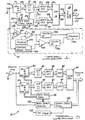
- the apparatus 10 generally includes an input 12 which is coupled to an input 14a of a capture circuit 14 and an input 15 of a mass defect detector circuit 16. An output 14b of the capture circuit 14 is coupled to an input 18a of an analog-to-digital converter 18.
- a memory device 20 containing a plurality of delta-mass tables (referred to hereafter simply as the “delta-mass tables 20") is coupled in communication with the mass defect detector 16 via an output 20a and an input 20b, and further between the differentiator circuit 16 and the analog-to-digital converter (hereinafter "A/D" converter) 18 via outputs 20c and 20d, respectively.
- An output of the analog-to-digital converter 18b is coupled to an input 22a of a first input FIFO buffer 22 and an input 24a to a second input FIFO buffer 24.
- Each of the buffers 22 and 24 include an output 22b and 24b, respectively, which are coupled to inputs 26a and 26b, respectively, of a digital signal processor 26.
- An output of the digital signal processor 26c is in turn coupled to an input 28a of an output FIFO buffer 28.
- An output 28b of the output FIFO buffer 28 is coupled to an external computer through a conventional input/output bus.
- the capture circuit 14 represents circuitry which may either integrate each incoming ion signal within an ion source extraction (hereinafter referred to as a "transient") or, alternatively, may comprise peak detection circuitry for detecting the peak of each ion signal within the transient.
- the apparatus 10 of the present invention it is a principal advantage that operation of the capture circuit 14 is not initiated until the calculated time of arrival of each ion, and then only for a user predetermined (but variable) data collection time window. This is accomplished by use of the delta-mass tables 20.
- the delta-mass tables 20 include a plurality of predetermined time delays corresponding to the expected (i.e., calculated) times of arrival of each and every ion peak within a transient having a specific mass-to-charge ratio. In time of flight analysis, the exact determination of arrival time for all masses requires only the exact flight times for two ions having known mass-to-charge ratios.
- the apparatus 10 Prior to any analysis, the apparatus 10 is precalibrated. This may involve use of an accurate time base oscilloscope to determine the time offset (t offset ) and slope (K) constants for a given set of instrumental parameters by the application of the above equation to two known m/z's. The determined constants are valid for all data collected under operating conditions where the instrumental parameters remain unchanged. On the basis of the above equation, the arrival times of all ions having sequential mass-to-charge ratios throughout the spectrum being analyzed can be calculated.
- the second time delay applied will represent the time increment from the beginning of the data collection window during detection of the first group of incoming isomass ions to the time at which the capture circuit 14 is again turned on to detect the next group of incoming isomass ions, and so forth for each successive ion peak within a transient.
- the time delay values in the delta-mass tables 20 are accurate to the nearest two nanoseconds.
- the data collection time window mentioned above represents a user settable time interval, preferably within a range of about 40-70 nanoseconds, during which the capture circuit 14 is turned on.
- the full spectrum of mass intensity information can be obtained while enabling the capture circuit 14 to generate significantly less data than would otherwise be generated if the capture circuit 14 were active during the times that no ions were arriving at the capture circuit 14.
- mass mapped acquisition typically only about 500 data points (i.e., points at which an ion peak is expected) over a transient need to be taken rather than typically about 20,000 data points taken by prior systems that sample the transient at a large plurality of evenly spaced data points (e.g., every 5ns), in an effort to detect every ion peak in the transient.
- the mass mapped acquisition system described herein typically reduces the number of data conversions required by the A/D convener 18, and thus the amount of data generated, by one or two orders of magnitude. This, in turn, allows considerably less expensive and less powerful processing and storage hardware to be used without sacrificing performance and resolution of the mass spectrum analysis.
- the mass defect detector 16 corrects for the "shift" in actual ion arrival times caused by the mass defect of molecules being measured by applying compensation factors to the calculated time values stored in the delta-mass tables 20.
- the mass defects arise from deviations from integer values in the atomic masses of various elements. For example, carbon has been assigned an atomic mass of 12.000. All other atomic masses are related to the mass of this element; they are nearly integer values, but not exactly. For example, the mass of hydrogen is 1.005 and oxygen is 15.997. These deviations from integer values are known as "mass defects".
- Mass defects can be positive (i.e., greater than the integers) such as for hydrogen or a negative (less than the integer value) such as for oxygen.
- Small molecules present little problem in the determination of exact arrival times of ions having varying masses. For larger molecules, however, the cumulative summation of mass defects may interfere greatly with the accurate determination of exact arrival times of ions within the ion source extraction. When all of the atoms within a heavier organic molecule are summed, the difference between the actual mass and the calculated mass using the integer values are called the "molecular mass defect".
- the correction applied by the mass defect detector 16 is based on two assumptions: 1) different ion fragments resulting from the same molecule will have similar mass defects, and 2) the molecules can be assigned in their mass defect to one of at least four classes.
- the four classes are "normal”, “slightly positive”, “moderately positive” and “slightly negative”. This creates four classifications for which determinations can be made to yield four independent delta-mass tables, which are referred to collectively by reference numeral 20 in Figure 1. Since the objective of high-speed, medium resolution mass spectrometry has traditionally been nominal mass accuracy, the use of the appropriate table results in mass assignments sufficiently accurate to accomplish the objective of correcting for deviations from the calculated arrival times for all ions.
- the mass defect detector 16 insures that the capture circuit is turned on at precisely the proper times so that every ion peak will fall at the approximate midpoint of the data collection window. It will be appreciated by those skilled in the art, however, that there is no limit to the number of delta-mass tables that may be employed if more than four are desired. In practice, the number of tables used will depend on the size of the data collection window and the resolution needed.
- the mass defect detector 16 ( Figure 1) of the present invention includes a differentiator 16a, a comparator 16b, a threshold signal source 16c, a first counter 16d, a data collection window timer 16e, an edge timing comparator 16f, a second counter 16g, and a processor 16h.
- the data collection window timer 16e receives a signal from the delta-mass table 20, which has been selected by an output of the processor 16h.
- an ion source extraction pulse is applied to generate an ion source extraction which will subsequently generate a transient waveform at the ion detector which is fed to the capture circuit 14.
- the delta mass table in concert with the master clock will cause an initial time delay which corresponds to the calculated arrival time of the lightest of the ions of interest to be applied before turning on the capture circuit 14 for the first group of incoming isomass ions.
- the capture circuit 14 acts to determine either the summed total intensity of ions having the first predetermined mass-to-charge ratio, or alternatively, the peak ion signal of all ions having the first predetermined mass-to-charge ratio.
- the capture circuit 14 is turned on just prior to the arrival of the lightest ions of interest for the predetermined data collection time window which, as described above, is preferably in the range of about 40-70 nanoseconds. More specifically, the capture circuit 14 is turned on before the calculated arrival time of ions having the first predetermined mass-to-charge ratio by about 20-35 nanoseconds (i.e., approximately 1/2 the total time of the data collection window) so that the incoming ion peaks will each be approximately centered within their data collection time windows.
- the differentiator 16a of the mass defect detector 16 simultaneously receives the arriving signal and differentiates this signal to produce signals representative of the slopes of the ion peaks thereof.
- the differentiated signals are output to the comparator 16b which compares the rising edge of the differentiated signals against a threshold signal from the threshold signal source 16c. Whenever the differentiated signal exceeds the threshold signal the comparator 16b generates an output signal to the first counter 16d and to the edge timing comparator 16f.
- the first counter thus contains a count of the number of ion peaks whose derivative is above the predetermined threshold signal from the threshold signal source 16c.
- the differentiated signals from the comparator 16b are simultaneously received by the edge timing comparator 16f and compared against a signal from the data collection window timer 16e.
- the signal from window timer 16e is generated after the first half of the data collection time window has expired.
- An output from the edge timing comparator 16f is generated each time an ion peak arrives during the second half of the data collection time window.
- the output of the comparator 16f is input to the counter 16g, which accumulates, in real time, a running count of the total number of ion peaks arriving during the second hail of the time window throughout a designated portion of the transient waveform.
- the processor 16h determines that an overwhelming majority of ion peaks are occurring in the second half of the time collection windows, then for the next transient it will cause a delta-mass table to be employed that will contain increased time delays between the successive data collection windows, to thereby "shift" the data collection windows such that each window is approximately centered over each of the incoming ion peaks. Conversely, if the majority of ion peaks are determined to be occurring in the first halves of the data collection windows, then a delta-mass table with shortened time delays between successive data collection time windows will be used for the next transient. This will cause the data collection windows to be shifted such that each occurs slightly prior to the previously calculated arrival times for the ion peaks. In this manner, by keeping the calculated times of arrival congruent with the actual times of arrival the full magnitude of each of the ion peaks is always obtained.
- the capture circuit 14 In each data collection window that has been opened, the capture circuit 14 generates an analog signal at its output 14b which represents the intensity of ions within the transient which have the predetermined mass-to-charge ratio for that window. This output is transmitted to the input 18a of the A/D converter 18.
- the A/D converter 18 is preferably an 8-bit A/D converter although it will be appreciated that A/D converters providing either greater or lesser resolution may be used depending upon the requirements of a specific application.
- the output 18b of the A/D converter 18 is a series of successive 8-bit digital signals (i.e., "words") each of which is representative of the ion intensity of an ion peak captured by the capture circuit 14.
- This 8-bit number is transmitted either to input 22a or input 24a of the first or second input FIFO buffers 22 and 24, respectively.
- the input FIFO buffers 22 and 24 subsequently store the digital information from the A/D convener 18 for alternate, complete transients.
- Each buffer 22 and 24 operates as a first-in-first-out buffer and each is addressed (i.e., read out) by the digital signal processor 26 in alternate fashion on alternate transients.
- the second input FIFO buffer 24 will be filled with data from the next transient. Subsequently, the second input FIFO buffer 24 will be read out by the digital signal processor 26 while the first input FIFO buffer 22 begins filling with data from the next successive transient. In this manner there is no interruption in the data collection processes caused by the digital signal processor 26 on the information output from the A/D converter 18 and processing throughput is maximized.
- the digital signal processor 26 reads out the input FIFO buffer 22 or 24, the information stored in either buffer is processed in real time by the digital signal processor 26 to sum the integrated or peak ion signals of ions within successive transients having the same mass-to-charge ratios in a m/z locked registry therein. Summation of the ion intensities of all of the m/z values in successive transients over a user-determined number of transients produces a file representative of a single mass spectrum. Repetition of the summation processes creates successive spectra, contiguous in time and continuous in operation, without interruption or loss of information. Accordingly, the apparatus 10 enables time array detection techniques to be employed in time of flight mass spectrometry with maximum utility for continuously varying samples.
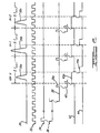
- a timing diagram is shown illustrating the relationship between numerous waveforms during detection within a particular transient.
- the transient is represented by waveform 30 having a first ion peak 30a, a second ion peak 30b and a third ion peak 30c.
- Also illustrated in relation thereto is a master clock pulse train 32, an extraction pulse 34, a waveform indicating the pre-time period 36, a "coarse” time waveform 38, a "fine” time waveform 40, a waveform 42 indicating the data collection time window, and a waveform 44 indicating the on-time of the A/D converter 18 ( Figure 1).
- the pre-time delay is applied which corresponds to the initial time delay between the time when the extraction pulse is first applied and when the first (i.e., lightest) ions of interest reach the detector.
- a divide down clock At the end of the pre-time period, for which there will be only one for each ion source extraction, a divide down clock generates a "course" pulse 38a which, in turn, is used to synchronize operation of a "fine” divide down clock.
- the fine divide down clock generates an extremely reproducible (from 1ns-20ns) clock signal which is used to trigger a one-shot multivibrator, which in turn is used to cause the capture circuit 14 to become operational.
- the capture circuit 14 is turned on for the time interval 42a, which represents the first data collection time window.
- the A/D converter 18 is turned on, as indicated by time interval 44a. From Figure 2 it should be appreciated that the data collection time window is implemented such that the first incoming ion peak 30a will fall approximately in its center (i.e., at its midpoint).
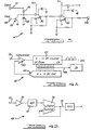
- the circuit 14 generally includes an input resistor 46, an input capacitor 48, a first amplifier stage 50 and a second amplifier stage 52.
- a clear input 54 is also provided for enabling the input capacitor 48 to be discharged through a MOSFET 56.
- the capture circuit 14 is initiated after each expiration of a predetermined time delay controlled by the contents of the delta-mass table being used.
- the capture circuit 14 remains active throughout the data collection window time period. During this time, the input resistor 46 and input capacitor 48 act as an integrator, thus integrating the ion signal of the transient.
- the integrated signal is then amplified by the first amplifier stage 50 and the second amplifier stage 52, and captured to accommodate the width of the data collection window in order to provide stable signal levels appropriate for the A/D converter 18 ( Figure 1).
- a stable, integrated signal is provided at the output 14b for subsequent input to the A/D converter 18.
- the A/D conversion is initiated.
- the input capacitor 48 is cleared by a signal applied to the clear input 54, which turns on the MOSFET 56, thus allowing the input capacitor 48 to discharge through the MOSFET 56 to ground.
- an alternative embodiment 58 of the A/D converter circuit 18 is shown for measuring the magnitude of the integrated or peak ion current in a manner minimizing the effect of noise on the analog signal.
- This device may replace the flash A/D converter in the embodiments described above or, as shown in Figure 4A, may be employed in a scheme enabling ion peak integration to be performed in the digital domain as an alternative to the analog integration of the embodiments described herein.
- Circuit 58 includes a comparator 60, a digital up/down counter 62 and a digital-to-analog (D/A) converter 64.
- the digital counter 62 is clocked at a very high frequency, preferably at about one GHz.
- the comparator 60 receives the incoming ion signals on its non-inverting input and outputs a digital signal, for example, a logic high level signal, whenever the transient exceeds the signal applied back to the inverting input of the comparator 60.
- a count is generated therein. The count is output as a digital signal to the digital-to-analog converter 64 which converts the digital signal into a representative analog signal which is applied to the inverting input of the comparator 60.
- the circuit 58 "tracks" the ion peaks of the transient. Accordingly, the digital signal in the counter 62 is incremented or decremented depending upon the changing magnitude of the ion intensity signal.
- the digital signal in counter 62 is also fed via an output 66 to a limited size, high speed digital summing register, such as a digital summing register 74, shown in more detail in Figure 4B and discussed in more detail momentarily. Accordingly, the integration of the ion peak currents may be performed in digital fashion.
- the resulting count in the counter 62 after a single ion peak of the transient has passed will be a digital representation of the peak ion intensity which is output to the input FIFO buffers 22, 24 shown in Figure 1.
- peak detection of the incoming ion peaks is performed digitally, in real time, as opposed to by analog techniques.
- Circuit 68 includes an amplifier 70, a high speed flash analog-to-digital (A/D) converter 72 and a limited size high speed digital summer 74.
- the transient is received at the input 12 before being amplified by the amplifier 70.
- the high speed flash A/D converter 72 generates a digital representation of each of the instantaneous ion currents within the transient which is being detected. This digital signal is transmitted to the digital summer 74.
- the digital summer 74 sums the successive digital signals generated by the high speed A/D converter 72 within the confines of each data collection window.
- the digital summer circuits may be directed to output either the sum (integration) or maximum (peak current) digital signal subsequent to the end of each data collection window.
- integration of peak intensities can be accomplished in the digital domain by immediately converting the incoming analog ion signals into representative digital signals.
- the output signal of each of the circuits 58 and 68 represents a single maximum value indicative of either the peak ion intensity or the integrated ion intensity for each group of ions having the same mass-to-charge ratio.
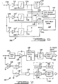
- Capture circuit 80 is controlled so as to become operational only upon the arrival of ions having odd numbered mass-to-charge ratios.
- Capture circuit 82 is controlled to become operational only during the arrival of ions having even numbered mass-to-charge ratios.
- Capture circuit 80 includes its own A/D converter 84, its own input FIFO buffer 86 and its own digital signal processor 88. Accordingly, all of the information processing of the information generated by the capture circuit 80 is controlled without regard to the arrival of ions having even numbered mass-to-charge ratios.
- the capture circuit 82 includes its own A/D converter 90, its own input FIFO buffer 92 and its own digital signal processor 94.
- processing of the information from the capture circuit 82 takes place independently of the arrival of ions having odd numbered mass-to-charge ratios.
- Each of the digital signal processors 88 and 94 transmit their output to a scan file FIFO output buffer 96 which subsequently outputs same to an external computer which merges the files into a complete spectrum file.
- a third digital signal processor may be incorporated into this embodiment to merge the two files into single complete spectrum file prior to transfer to an attending computer system for processing and output.
- the processing of information from each of the capture circuits 80 and 82 by their corresponding components is identical to that described in connection with Figure 1.
- the apparatus 78 includes memory means for storing a plurality of delta-mass tables 95, mass defect detection circuitry 100, a time of flight trigger 102, and a system clock/timing circuit 104.
- the delta-mass tables 98 and mass defect detection circuitry 100 are identical to the delta-mass tables 20 and mass defect detector 16 of the apparatus 10 of Figure 1.
- the time of flight trigger 102 preferably comprises a conventional trigger circuit for initiating the ion extraction pulses.
- the system clock/timing circuit 104 controls the time of flight trigger 102 to provide a means by which the operation of the mass mapped acquisition and the mass defect detection circuit 100 can be synchronized to the ion source extraction pulse.
- the capture circuits 80 and 82 are made operational alternately just prior to the expected arrival times of ions having even and odd numbered mass-to-charge ratios. While the capture circuit 80 is detecting the intensity of ions having an odd number mass-to-charge ratio, capture circuit 82 is turned off. Subsequently, capture circuit 80 is turned off and capture circuit 82 becomes operational just prior to the expected arrival time of a group of ions having an even number mass-to-charge ratio. While capture circuit 82 is operational, the information generated by capture circuit 80 is processed by components 84, 86 and 88 and transmitted to the output FIFO buffer 96.
- the capture circuit 80 will again be turned on just prior to the expected arrival time of the group of ions having the next odd number mass-to-charge ratio. While capture circuit 80 is operational, the information generated by capture circuit 82 is processed by components 90, 92 and 94 and transmitted to the output FIFO buffer 96. This dual capture approach provides adequate timing for even the high-mass range where the ion peaks are in closest proximity to each other. The use at two input FIFO buffers 86 and 92 maximizes system throughput because while one buffer is being filled, the other is being read out by its associated digital signal processor.
- the asynchronous nature of the sequential operations of loading the input FIFO buffers 86 and 92, and the unloading and processing by the digital signal processors 88 and 94, enables continuous operation of the apparatus 78 for very long periods of time without loss of data. While many heretofore developed data systems are only able to obtain one to two scans per second, the apparatus 78 can yield 50-200 or more scan files per second.
- the apparatus 78 readily enables modular expansion of additional capture circuits to facilitate same.
- an alternative embodiment of the apparatus of Figure 5 could be readily constructed which incorporates an even larger plurality of capture circuits sufficient to enable the collection of, for example, 10 or more points across each and every ion peak within a transient. Driven by suitable delta-mass tables, this configuration would yield a mass axis resolution analogous to that of the quadrupole or single focusing magnetic sector mass spectrometers.
- fractional mass dependent data obtained by this apparatus and technique could then be subjected to centroiding or other mathematical processing to gain fractional mass resolution sufficient for applications such as electrospray mass spectrometry where ions having multiple charges are encountered. Additionally, if narrow peak data collection windows are used, real time profiles of the mass spectra may be produced with this mode of operation.
- FIG. 6 there is shown yet another integrating transient recorder apparatus 106 in accordance with another alternative preferred embodiment of the present invention.
- the apparatus 106 operates in analog fashion to sum (i.e., integrate) ions having similar mass-to-charge ratios for succeeding incoming transients.
- the apparatus 106 is preferably used whenever ions having a limited number of different mass-to-charge ratios are desired to be measured, rather than the continuous mass spectrum.
- the apparatus 106 consists of a plurality of boxcar integrators 108, 108' and 108''. It will be understood immediately, however, that a greater or lesser number of integrators 108 could be used to suit the needs of specific applications and that the illustration of three boxcar integrators has been shown merely to illustrate that a plurality of integrators can be controlled sequentially to provide analog summing of similar mass-to-charge ratio ions.
- the apparatus 106 further includes amplifiers 110, 110' and 110'' for each integrator 108, 108' and 108'', respectively.
- Each integrator 108, 108' and 108'' is further coupled to an analog-to-digital control and multiplexer select circuit 110 through control lines 110a, 110b and 110c which controls switches 112a, 112b and 112c, respectively.
- a second plurality of switches 114a, 114b and 114c are further controlled via lines 116a, 116b and 116c, respectively, by the delta-mass tables circuitry 116 enabling the boxcar integration timing function.
- each boxcar integrator 108, 108' and 108'' is turned on by a signal from its corresponding control line 116a, 116b, 116c at an appropriate time in accordance with a predetermined time delay value from the delta-mass tables 116, which controls the opening and closing of switches 114a, 114b and 114c. Accordingly, each boxcar integrator 108, 108', 108'' only receives ions having a predetermined mass-to-charge ratio.
- Each of the boxcar integrators 108, 108', 108'' are further controlled by the multiplexer select circuit 110, which causes the output of each integrator 108, 108', 108'' to be transmitted to an A/D converter 118 by controlling the opening and closing of the appropriate switch 112a, 112b, 112c.
- Ions having a first expected time of arrival are input to the integrator 108 by closing switch 114a shortly before their expected time of arrival.
- the same mass-to-charge ion packet from successive transients are introduced into the integrator by the boxcar action for a preset number of transients and for a preset amount of time.
- the integrated signal generated by integrator 108 is then output to the A/D 118 by closing the switch 112a. At this time switches 114b, 114c and 112b, 112c are all open.
- switches 114a and 114c Prior to the anticipated arrival time of the next selected m/z ions, switches 114a and 114c are opened while switch 114b is closed by the signal on line 116b.
- the ions in successive transients arriving at the second anticipated arrival time are input to the integrator 108' again over the preset number of transients and the integrated output thereof is transmitted to the A/D converter 118 when switch 112b is closed.
- switches 114a, 114b and 112a, 112b and 112c Prior to the anticipated arrival time of the third group of ions, switches 114a, 114b and 112a, 112b and 112c are open and switch 114c is closed by the appropriate signal on line 116c.
- Ions arriving at the third anticipated time of arrival are integrated by the boxcar integrator 108'' again over the preset interval of successive transients and transmitted to the A/D converter 118 through the subsequent closure of switch 112c. Accordingly, as succeeding transients progress, the analog signals being captured for each selected group of ions are integrated or summed, providing an output that is the sum of the multiple input analog ion peaks. Since the masses to be measured are preselected, the results of digitization will furnish the information for the generation of a partial mass spectrum consisting only of the ions having the selected mass-to-charge ratios. From this point, this partial mass spectrum will be processed in a manner analogous to the other preferred embodiments described herein.
- an "Ad Lib" transient recorder 120 is shown in connection with another alternative embodiment of the present invention.
- the data collection window is initiated by detection of the incoming ion peak, in contrast to the other preferred embodiments described herein which initiate the data collection window in accordance with predetermined time delays from the delta-mass tables.
- the apparatus 120 generally comprises a time delay circuit 122, an integrator 124 or an optional peak capture circuit 126, an A/D converter 128 and an input FIFO buffer 130.
- An incoming transient is further directed to a differentiator 132 which provides signals representative of the instantaneous rate of change of each of the ion peaks being received.
- the output of the differentiator 132 is input simultaneously into a threshold detector 134 and a zero crossing detector 136.
- the outputs of the detectors 134 and 136 are gated via an AND-gate 138 to a timing circuit 140.
- the timing circuit 140 includes a clock 142 for generating a clock pulse applied to a digital counter 144.
- a latch 146 is responsive to the output of the AND-gate 138 and operates to latch the count in the counter 144 upon receipt of a signal from the AND-gate 138.
- the clock FIFO buffer 148 temporarily stores the output of the latch 146 before the information is read to an external digital signal processor.
- the incoming ion peaks are received by the differentiator 132 and the delay circuit 122 simultaneously.
- the delay circuit 122 delays the incoming ion peak signal to account for fixed, predetermined delays introduced by the differentiating, threshold sensing and zero crossing circuitry (132, 134, 136).
- the differentiated output signal of the differentiator 132 is supplied to the threshold detector 134 and the zero crossing detector 136.
- the comparator 134 initiates operation of the data collection processes in a manner exactly similar to those of the prior described embodiments in an action analogous to that of the delta-mass tables 124.
- the delay time 122 allows the decision to measure an incoming ion peak to be made prior to the appearance of the signal at the input of the measuring circuitry 124.
- the ion extraction pulse also simultaneously initiates operation of the clock 142, which begins applying a clock signal to the counter 144, which in turn begins accumulating a count indicative of the time lapse since the ion source extraction pulse was applied.
- the zero crossing detector 136 detects when the slope of each ion peak has crossed zero to thus provide an exact measurement of the center of each incoming ion peak. At each such instant the zero crossing detector 136 provides an output signal to an input of the AND-gate 138 indicative of same. At the instant that the AND-gate receives signals from both sources 134 and 136 it generates an output signal which triggers the latch 146. When the latch is triggered it "latches" the count of the counter 144 at that instant and transmits the latched count to the clock FIFO buffer 148. The latched count indicates the precise arrival time of each incoming ion peak.
- the ion peak will then be integrated by the integrator 124 or the peak ion intensity determined by the peak capture circuit 126 before being transmitted to the A/D converter 128.
- the A/D converter 128 provides a digital representation of the analog output of the integrator 124 (or the peak capture circuit 126) and temporarily stores this output in the input FIFO buffer 130.
- the counter will be latched by the latch 146 when the threshold detector 134 and zero crossing detector 136 concurrently provide signals to the AND-gate 138.
- the clock FIFO 148 will contain a digital value (preferably at least a 16 bit digital word) representative of the time of arrival of the ion being detected.
- the measured times read out from the clock FIFO buffer 148 will preferably be converted into mass-to-charge values subsequent to the spectrum generation. It is expected that this embodiment will be used whenever the mass range to be scanned is very great and, secondly, when ions of charge greater than one are encountered. Such ions present themselves as non-nominal masses which cannot be calculated prior to data collection as can be done when a charge on the ion is equal to one.
- the apparatus 120 of Figure 7 may further be operated in two modes.
- the first mode in which nominal mass resolution is desired, the summing of the individual ion peaks from subsequent transients will be made using peak time clock values which are created by ignoring the last three significant bits of the digital signal from the clock FIFO buffer 148. This enables high speed time array detection.
- a second operational mode is utilized when ions with a charge greater than one are encountered. In this situation, each cluster of arrival times of individual ions from successive transients will be averaged to yield a final 16 bit value for the arrival time of the ions in that particular group.
- the apparatus 120 utilizes all of the features of the previous embodiments described herein with the exception of substituting for the predetermination of arrival times the concept of peak detection as the controlling determinant of the beginning point of the data collection window and the data collection process.
- the clock storage feature of the Ad Lib embodiment 120 of Figure 7 can be implemented using the hardware of the embodiments of Figures 1, 5 and 6 and the utility of the FIFO buffer expanded by automatically incrementing the FIFO buffer address as a continuous "event clock", with the buffer storing the intensity value in a buffer location appropriate to the time of arrival of the measured ion transient.
- FIG. 8 there is shown an apparatus circuit 150 for increasing the range of measurement of a standard A/D converter such as that used in the preferred embodiments disclosed herein.
- the apparatus 150 automatically expands the range of measurement capability of a standard A/D converter depending on the magnitude of the gain of the analog input to the A/D converter.
- the apparatus 150 generally includes a first amplifier 154 having a unity gain, a second amplifier 156 having a gain of four and a third amplifier 158 having a gain of sixteen. Outputs from each of the amplifiers 156-158 are output independently to an associated comparator 160, 162 and 164. Outputs of the comparators 160-164 are input into a range control circuit 166.
- the range control circuit 166 has three control outputs 166a, 166b and 166c which each control independent switches 168, 170 and 172 in series with the outputs of the amplifiers 154-158. Selective closing of one of the switches 168-172 couples its associated amplifier output with the A/D converter 152.
- the output of the A/D converter (for example, an 8-bit analog-to-digital converter) 152 is input into a range select gating circuit 174 having, for example, a 12-bit output 174a.
- a range select data output 176 from the range control circuit 166 is input to the range select gate 174 for controlling which of bits 0-11 of the 12-bit output word are coupled to the output of the A/D converter 152.
- each ion peak in the incoming transient is amplified by each one of the amplifiers 154, 156 and 158 and a comparison made between each amplified ion peak and a reference signal on the non-inverting input of each one of the comparators 160, 162 and 164.
- the range control circuit 166 outputs a signal on control line 166c which causes switch 172 to remain closed. Closure of switch 172 couples the output of the highest gain amplifier 158 to the input of the analog-to-digital converter 152 while switches 168 and 170 remain open.
- the A/D converter 152 receives the first incoming ion peak which has been increased in gain by a factor of 16.
- the A/D converter 152 generates an 8-bit digital output representative of the analog input it receives. This output is caused to be coupled to outputs 174a 0 - 174a 7 by a signal from the range control circuit 166 on range select data control line 176. Accordingly, an 8-bit digital word is generated from the 8 bit output of the A/D converter 152.
- the range control circuit 166 generates a control signal on control line 166b.
- the signal on control line 166b closes the switch 170, thus coupling the output of amplifier 156 to the input of the A/D converter 152.
- the 8-bit output of the A/D converter 152 is then coupled to outputs 174a 2 - 174a 9 of the range select multiplexer 174 via an appropriate control signal on range select data line 176.
- a 10 bit word is generated in which bits 0-1 will be zero.
- the range control circuit 166 transmits a control output on control line 166a.
- the control signal on control line 166a causes the switch 168 to close, thus coupling the output of the amplifier 154 to the input of the A/D converter 152.
- the 8-bit output of the A/D converter 152 is then coupled to outputs 174a 4 - 174a 11 creating a 12 bit output word.
- the range of measurement will be increased or decreased automatically by providing an output from the range select gate 174 having a varying bit displacement.
- the apparatus 150 provides increased measurement capability without the need for additional software or complicated timing circuitry, and also without sacrificing precision of the A/D converter 152 while gaining a higher output range.
- the apparatus 10 of the present invention is shown in simplified block diagram form in combination with a mass spectrometer 178, a data handling system 180, and a computer system 182 having an interactive console 184.
- the control functions, instrumental parameters and data collection parameters are entered by the operator into the computer 182 via the console 184. This information is passed to the apparatus 10 where the actual control of the data timing, data collection, data summation and data transfer processes occur.
Landscapes
- Chemical & Material Sciences (AREA)
- Analytical Chemistry (AREA)
- Other Investigation Or Analysis Of Materials By Electrical Means (AREA)
Claims (22)
- Vorrichtung (10,78,106,120) zum Detektieren einer Vielzahl von Ionen-Peaks (30a,30b,30c) innerhalb wenigstens eines Übergangs in einem Flugzeitmassenspektrometer, wobei der Übergang in Antwort auf einen Ionenquellen-Extraktionspuls (34) erzeugt wird,
dadurch gekennzeichnet, dass die Vorrichtung umfasst:eine Signal-Detektor-Einrichtung (14,80,82,124,108), die auf die Ionen-Peaks reagiert, um jeden der Ionen-Peaks zu detektieren und ein Ausgangssignal zu erzeugen, das die Intensitäten in den Ionen-Peaks anzeigt, wobei jeder Ionen-Peak ein vorbestimmtes Massen-Ladungs-Verhältnis aufweist;eine Einrichtung (16;20;132,134,136,138,140;116), um die Signal-Detektor-Einrichtung kurz vor einer vorbestimmten Ankunftszeit von jedem Ionen-Peak an der Signal-Detektor-Einrichtung einzuschalten und um die Signal-Detektor-Einrichtung nur für ein vorbestimmtes Zeitfenster zur Datensammlung danach angeschaltet zu lassen, so dass die Signal-Detektor-Einrichtung die Ausgabe-Signale nur zu Zeiten erzeugt, während derer die Ionen-Peaks an der Signal-Detektor-Einrichtung ankommen; undeine Einrichtung (26) zum Verarbeiten der Ionen-Peaks, um eine Massenspektrum-Datei zu erzeugen, welche die Intensitäten der Ionen-Peaks anzeigt. - Vorrichtung nach Anspruch 1, welche ferner eine Massendefekt-Detektor-Einrichtung (16;100,98;116) umfasst, um eine tatsächliche Ankunftszeit für jeden Ionen-Peak an der Signal-Detektor-Einrichtung zu überwachen und um die Verschiebung des Zeitfensters zur Datensammlung in Übereinstimmung mit der tatsächlichen Ankunftszeit von jedem Ionen-Peak zu veranlassen, so dass jeder Ionen-Peak in ein ungefähres Zentrum des Zeitfensters zur Datensammlung fällt.
- Vorrichtung nach Anspruch 2, bei welcher die Massendefekt-Detektor-Einrichtung eine Vielzahl von Delta-Massen-Tabellen (20;98;116) umfasst, wobei jede Tabelle eine Vielzahl von Zeitverzögerungs-Werten enthält, um zu veranlassen, dass die Signal-Detektor-Einrichtung zu Zeiten angeschaltet wird, die kurz vor der erwarteten Ankunftszeit von jedem Ionen-Peak, die von einem Massendefekt des Ionen-Peaks abhängt, liegen, um dadurch die Verschiebung von jedem Zeitfenster zur Datensammlung zu veranlassen, so dass jeder Ionen-Peak vollständig innerhalb eines der Zeitfenster zur Datensammlung fällt.
- Vorrichtung nach Anspruch 2, bei welcher die Massendefekt-Detektor-Einrichtung eine Vielzahl von Delta-Massen-Tabellen (16;98;116) umfasst, wobei jede Tabelle eine Vielzahl von Verzögerungszeit-Werten enthält, um zu veranlassen, dass die Signal-Detektor-Einrichtung vor den vorbestimmten Ankunftszeiten angeschaltet wird, wenn die Ionen-Peaks übereinstimmend in der ersten Hälfte des vorbestimmten Zeitfensters auftreten oder um zu veranlassen, dass die Signal-Detektor-Einrichtung nach den vorbestimmten Ankunftszeiten angeschaltet wird, wenn die Ionen-Peaks übereinstimmend in der zweiten Hälfte des vorbestimmten Zeitfensters auftreten.
- Vorrichtung nach einem der Ansprüche 1 bis 4, bei welcher die Verarbeitungseinrichtung umfasst:eine Einrichtung zum aufeinanderfolgenden Aufsummieren der Ionen-Peaks von aufeinanderfolgenden Übergängen, die ein ähnliches Massen-Ladungs-Verhältnis aufweisen; undeine Einrichtung zum Speichern der aufsummierten Ionen-Peaks, die ähnliche Massen-Ladungs-Verhältnisse aufweisen, in einem zeitlich abgeschlossenen Register, uni eine Massenspektrum-Datei zu erzeugen.
- Vorrichtung nach einem der Ansprüche 1 bis 5, welche ferner umfasst, eine Analog/Digital-Wandlereinrichtung (18,84,90), die auf die Ausgabesignale der Signal-Detektor-Einrichtung reagiert, um Digitalsignale bereitzustellen, welche die Intensität von jedem der Ionen-Peaks darstellt;einen ersten FIFO-Eingabe-Puffer (22,86), der auf die Analog/Digital-Wandlereinrichtung reagiert, um zeitweise die digitale Ausgabe der Analog/Digital-Wandlereinrichtung zu speichern;einen zweiten FIFO-Eingabe-Puffer (24,92), der auf die Analog/Digital-Wandlereinrichtung reagiert, um zeitweise die digitale Ausgabe der Analog/Digital-Wandlereinrichtung zu speichern;
wobei die Verarbeitungseinrichtung auf den ersten FIFO-Eingabe-Puffer und den zweiten FIFO-Eingabe-Puffer reagiert, um erste digitale Signale von dem ersten FIFO-Eingabe-Puffer auszulesen und zu verarbeiten, während die digitale Ausgabe der Analog/Digital-Wandlereinrichtung in den zweiten FIFO-Eingabe-Puffer geladen wird, am zweite digitale Signale von dem zweiten FIFO-Eingabe-Puffer auszulesen und zu verarbeiten, während die digitale Ausgabe der Analog/Digital-Wandlereinrichtung in den ersten FIFO-Eingabe-Puffer geladen wird, und um aufeinanderfolgend ausgewählte Signale der ersten und zweiten digitalen Signale aufzusummieren, welche ähnliche Massen-Ladungs-Verhältnisse in einem zeitlich abgeschlossenen Register darstellen, um eine Massenspektrum-Datei zu erzeugen. - Verfahren nach irgendeinem vorhergehenden Anspruch, bei welchem die Signal-Detektor-Einrichtung eine Schaltungseinrichtung (46,48) zum Integrieren von jedem der Ionen-Peaks umfasst.
- Vorrichtung nach Anspruch 6 oder 7, welche ferner einen FIFO-Ausgabe-Puffer (28,96) umfasst, der auf die Ausgabe der Verarbeitungseinrichtung reagiert, um eine Massenspektrum-Datei, die durch die Verarbeitungseinrichtung erzeugt wird, zeitweise zu speichern.
- Verfahren nach einem der Ansprüche 6 - 8, welches ferner eine Einrichtung (150) zum automatischen Erhöhen des Messbereichs der Analog/Digital-Wandlereinrichtung in Antwort auf die Grösse von jedem der Ionen-Peaks umfasst.
- Vorrichtung nach Anspruch 9, bei welcher die Einrichtung zum Erhöhen des Messbereichs umfasst:eine Vielzahl von unabhängigen Verstärkern (154,156,158), wobei jeder eine unterschiedliche Verstärkung aufweist und auf die Ionen-Peaks reagiert; eine Vielzahl von Komparatoren (160,162,164), wobei jeder auf ein gemeinsames vorbestimmtes Referenz-Schwellen-Signal und eine Ausgabe von einem zugeordneten Verstärker reagiert;eine Bereichs-Steuerschaltung (166), die auf die Ausgabe der Komparatoren reagiert, um eine entsprechende Vielzahl von Schaltsteuersignalen (166a,166b,166c) und ein Bereichsauswahl-Signal, das von der Intensität von jedem Ionen-Peak abhängt, zu erzeugen;eine Vielzahl von Schaltern (168,170,172), wobei jeder mit einer Ausgabe von einem einzelnen der Verstärker verbunden ist, und auf die Schalteteuersignale reagiert, wobei die Schalter jeweils eine ausgewählte Verstärker-Ausgabe mit der Analog/Digital-Wandlereinrichtung koppeln in Antwort auf ein spezielles der Schalteteuersignale; undeine Bereichsauswahl-Multiplexer-Einrichtung (174), um eine Ausgabe von der Analog/Digital-Wandlereinrichtung und ein Bereichsauswahl-Signal zu empfangen und in Antwort darauf ein entsprechendes digitales Wort zu erzeugen, das eine grössere Bit-Länge als die Ausgabe der Analog/Digital-Wandlereinrichtung aufweist.
- Vorrichtung nach einem der Ansprüche 1 - 5, welche ferner eine zweite Signal-Detektor-Einrichtung (82) umfasst, die auf eine Einrichtung (98,100, 102,104) zum Anschalten der zweiten Signal-Detektor-Einrichtung reagiert um eine Vielzahl von zweiten Ausgabesignalen zu erzeugen, welche die Intensitäten von wenigstens ausgewählten Bereichen von ausgewählten Ionen-Peaks darstellen.
- Vorrichtung nach Anspruch 11, bei welcher die Einrichtung zum Anschalten der zweiten Signal-Detektor-Einrichtung eine Zeitgeber-Einrichtung (104) zum Anschalten der zweiten Signal-Detektor-Einrichtung und zum Steuern der Signal-Detektor-Einrichtung und der zweiten Signal-Detektor-Einrichtung umfasst, so dass nur eine eingeschaltet ist, während die Ionen-Peaks, die ein geradzahliges Massen-Ladungs-Verhältnis aufweisen, an der Signal-Detektor-Einrichtung und der zweiten Signal-Detektor-Einrichtung ankommen, und nur die andere angeschaltet ist, während die Ionen-Peaks, die ein ungeradzahliges Massen-Ladungs-Verhältnis aufweisen, bei der Signal-Detektor-Einrichtung und der zweiten Signal-Detektor-Einrichtung ankommen.
- Vorrichtung nach Anspruch 12, bei welcher die Signal-Detektor-Einrichtung nur bei einer ersten ausgewählten Zeit von der Vielzahl der vorbestimmten Ankunftszeiten der Ionen-Peaks angeschaltet wird, um dadurch nur Informationen einzufangen, die sich auf die Intensität der Ionen beziehen, die ein erstes vorbestimmtes Massen-Ladungs-Verhältnis aufweisen; undbei welcher die zweite Signal-Detektor-Einrichtung nur zu einer zweiten ausgewählten Zeit von der Vielzahl der vorbestimmten Ankunftszeiten der Ionen-Peaks angeschaltet wird, um nur Informationen einzufangen, die sich auf die Intensität der Ionen beziehen, die ein zweites vorbestimmtes Massen-Ladungs-Verhältnis aufweisen.
- Vorrichtung nach einem der Ansprüche 11 bis 13, welche ferner eine zweite Analog/Digital-Wandlereinrichtung (90) umfasst, welche auf die zweite Signal-Detektor-Einrichtung reagiert, um digitale Signale bereitzustellen, welche die zweiten Ausgabesignale der zweiten Signal-Detektor-Einrichtung darstellen.
- Vorrichtung nach Anspruch 1, bei welcher die Signal-Detektor-Einrichtung eine Integrier-Einrichtung (124) umfasst, welche auf die Ionen-Peaks reagiert, um die Ionen-Peaks innerhalb des Übergangs zu integrieren, um eine Vielzahl von integrierten Ausgabesignalen zu erzeugen, welche die Intensität von jedem Ionen-Peak darstellt, und bei welcher die Einrichtung (132,134,136) zum Anstalten der Signal-Detektor-Einrichtung eine Einrichtung zum Einschalten der Integrier-Einrichtung nach der Detektion eines Ionen-Peaks umfasst, und zwar nur für ein vorbestimmtes Zeitfenster, das ausreicht, wenigstens einen erwünschten Teil der Ionen-Peaks einzufangen, wobei die Vorrichtung ferner eine Analog/Digital-Wandlereinrichtung (128) umfasst, welche auf die Ausgabesignale von der Integrier-Einrichtung reagiert, um digitale Ausgabesignale, welche die integrierten Ausgabesignale darstellen, in Antwort darauf zu erzeugen.
- Vorrichtung nach Anspruch 1, umfassend:eine Integrier-Einrichtung (108, 108',108"), die auf die Ionen-Peaks reagiert, um Ionen-Peaks in dem Übergang zu integrieren, um eine Vielzahl von integrierten Ausgabesignalen zu erzeugen, welche die Intensität von jedem Ionen-Peak darstellen;eine Einrichtung (116) zum Anschalten der Integrier-Einrichtung, und zwar nur zu erwarteten Ankunftszeiten der Ionen-Peaks, und nur für ein vorbestimmtes Zeitfenster während jeder der erwarteten Ankunftszeiten, welches ausreicht, um wenigstens einen erwünschten Abschnitt der Ionen-Peaks einzufangen,eine Analog/Digital-Wandlereinrichtung (118), die auf die Ausgabesignale von der Integrier-Einrichtung reagiert, um digitale Ausgabesignale, welche die integrierten Ausgabesignale darstellen, in Antwort darauf zu erzeugen.
- Vorrichtung nach Anspruch 1, welche ferner umfasst:eine zweite Integrier-Einrichtung (108,108',108''), die auf die Ionen-Peaks reagiert, um ausgewählte der Ionen-Peaks aufzusummieren, welche ausgewählte Massen-Ladungs-Verhältnisse aufweisen, um eine Vielzahl von zweiten integrierten Ausgabesignalen bereitzustellen, welche die Intensität von jedem der ausgewählten Ionen-Peaks darstellen; undeine Multiplexer-Steuereinrichtung (110), um kontrolliert zu veranlassen, dass die Ausgaben der Integrier-Einrichtung und der zweiten Integrier-Einrichtung mit der Analog/Digital-Wandlereinrichtung gekoppelt werden und um den Betrieb der Analog/Digital-Wandlereinrichtung zu initiieren, so dass die Analog/Digital-Wandlereinrichtung aufeinanderfolgend anfänglich die integrierten Ausgabesignale von der Integrier-Einrichtung und anschließend die zweiten integrierten Ausgabesignale von der zweiten Integrier-Einrichtung in die digitalen Ausgabesignale bzw. die zweiten digitalen Ausgabesignale wandelt.
- Verfahren zum Durchführen einer Zeitfeld-Detektion in einen Flugzeit-Massen-Spektrometer, bei welchen die Bildung von jedem Ionen-Peak (30a,30b,30c) innerhalb jedes Übergangs durch eine Signal-Detektor-Einrichtung (14,80,82,124,108) gesammelt wird,
dadurch gekennzeichnet, dass das Verfahren die Schritte umfasst:a. Bestimmen der Ankunftszeit von jedem Ionen-Peak; undb. Anschalten der Signal-Detektor-Einrichtung zum Empfangen der Ionen-Peaks kurz vor der vorbestimmten Ankunftszeit von jedem der Ionen-Peaks und nur für ein vorbestimmtes Zeitfenster zum Datensammeln, welches ausreicht, es zu ermöglichen, dass jeder der Ionen-Peaks durch den Detektor detektiert wird, und Erzeugen einer Serie von Ausgabesignalen von der Signal-Detektor-Einrichtung, welche die Intensitäten der Ionen-Peaks darstellen; undc. Verarbeiten der Ionen-Peaks, um eine Massenspektrum-Datei zu erzeugen, welche die Intensitäten der Ionen-Peaks anzeigt. - Verfahren nach Anspruch 18, welches ferner die Schritte umfasst:d. Erzeugen einer Vielzahl von digitalen Signalen, welche die Serie der analogen Ausgabesignale darstellt;e. Speichern der digitalen Signale in einem FIFO-Eingabe-Speicher, wobei die Verarbeitung das Verarbeiten der digitalen Signale umfasst, um eine Informationsdatei zu erzeugen, welche die Aktivität des Detektors für den Übergang wiedergibt.
- Verfahren nach Anspruch 19, welches die Schritte umfasst:Wiederholen der Schritte b. bis e. für einen zweiten, darauffolgenden Übergang, und Aufsummieren der digitalen Signale, welche die Ionen-Peaks darstellen, welche ähnliche Massen-Ladungs-Verhältnisse in einem die Massen abbildenden Register aufweisen, um eine Massenspektrum-Abtastdatei zu erzeugen.
- Verfahren nach einem der Ansprüche 19 - 20, welches ferner die Schritte umfasst:Überwachen der Ankunft von jedem der Ionen-Peaks an der Signal-Detektor-Einrichtung, um eine tatsächliche Ankunftszeit von jedem der Ionen-Peaks innerhalb des Übergange zu bestimmen, und, wenn die tatsächlichen Ankunftszeiten von den erwarteten Ankunftszeiten abweichen, Zugreifen auf eine Delta-Massen-Tabelle (20,98,116), um Zeitverzögerungs-Korrekturwerte zu erhalten, die beim Anschalten des Detektors anzuwenden sind, um das vorbestimmte Zeitfenster zur Datensammlung zu verschieben, um zu veranlassen, dass jeder der Ionen-Peaks vollkommen innerhalb des vorbestimmten Zeitfensters zur Datensammlung empfangen wird.
- Verfahren nach Anspruch 21, bei welchem bestimmte der Zeitverzögerungs-Korrekturwerte veranlassen, dass die Signal-Detektor-Einrichtung vor den vorbestimmten Ankunftszeiten der Ionen-Peaks an geschaltet wird, wenn die Ionen-Peaks übereinstimmend in der ersten Hälfte des Zeitfensters auftreten; und bei welchem bestimmte andere der Zeitverzögerungs-Korrekturwerte veranlassen, dass die Signal-Detektor-Einrichtung nach den vorbestimmten Ankunftszeiten der Ionen-Peaks angeschaltet wird, wenn die Ionen-Peaks übereinstimmend in der zweiten Hälfte des Zeitfensters auftreten.
Applications Claiming Priority (3)
| Application Number | Priority Date | Filing Date | Title |
|---|---|---|---|
| US81731 | 1993-06-23 | ||
| US08/081,731 US5367162A (en) | 1993-06-23 | 1993-06-23 | Integrating transient recorder apparatus for time array detection in time-of-flight mass spectrometry |
| PCT/US1994/006892 WO1995000236A1 (en) | 1993-06-23 | 1994-06-17 | Transient recorder in time-of-flight mass spectrometer |
Publications (3)
| Publication Number | Publication Date |
|---|---|
| EP0746403A1 EP0746403A1 (de) | 1996-12-11 |
| EP0746403A4 EP0746403A4 (de) | 1997-05-07 |
| EP0746403B1 true EP0746403B1 (de) | 2000-08-16 |
Family
ID=22166025
Family Applications (1)
| Application Number | Title | Priority Date | Filing Date |
|---|---|---|---|
| EP94920263A Expired - Lifetime EP0746403B1 (de) | 1993-06-23 | 1994-06-17 | Transientenaufzeichnungsgerät für ein flugzeitmassenspektrometer |
Country Status (4)
| Country | Link |
|---|---|
| US (1) | US5367162A (de) |
| EP (1) | EP0746403B1 (de) |
| DE (1) | DE69425588T2 (de) |
| WO (1) | WO1995000236A1 (de) |
Families Citing this family (64)
| Publication number | Priority date | Publication date | Assignee | Title |
|---|---|---|---|---|
| DE4326549C1 (de) * | 1993-08-07 | 1994-08-25 | Bruker Franzen Analytik Gmbh | Verfahren für eine Regelung der Raumladung in Ionenfallen |
| DE19515270C2 (de) * | 1995-04-26 | 2000-05-11 | Bruker Saxonia Analytik Gmbh | Verfahren zur Messung von Ionenmobilitätsspektren |
| US6002127A (en) | 1995-05-19 | 1999-12-14 | Perseptive Biosystems, Inc. | Time-of-flight mass spectrometry analysis of biomolecules |
| US5625184A (en) * | 1995-05-19 | 1997-04-29 | Perseptive Biosystems, Inc. | Time-of-flight mass spectrometry analysis of biomolecules |
| US5712480A (en) * | 1995-11-16 | 1998-01-27 | Leco Corporation | Time-of-flight data acquisition system |
| US5777326A (en) * | 1996-11-15 | 1998-07-07 | Sensor Corporation | Multi-anode time to digital converter |
| AUPO557797A0 (en) * | 1997-03-12 | 1997-04-10 | Gbc Scientific Equipment Pty Ltd | A time of flight analysis device |
| US6094627A (en) * | 1997-05-30 | 2000-07-25 | Perkinelmer Instruments, Inc. | High-performance digital signal averager |
| US6052185A (en) * | 1997-06-30 | 2000-04-18 | Active Impulse Systems Inc. | Method and apparatus for measuring the concentration of ions implanted in semiconductor materials |
| US6101376A (en) * | 1997-11-05 | 2000-08-08 | Advanced Micro Devices, Inc. | Squelch circuit and methodology for a multi-level quantizer |
| JP3413447B2 (ja) | 1998-01-23 | 2003-06-03 | マイクロマス・リミテッド | 飛行時間質量分析計及びそれに対する検出器 |
| DE19808584C1 (de) | 1998-02-28 | 1999-08-26 | Bruker Daltonik Gmbh | Verfahren zur qualitativen Schnellauswertung analytischer Massenspektren |
| US7060973B2 (en) * | 1999-06-21 | 2006-06-13 | Ionwerks, Inc. | Multi-anode detector with increased dynamic range for time-of-flight mass spectrometers with counting data acquisition |
| US6878931B1 (en) | 2000-07-26 | 2005-04-12 | Agilent Technologies, Inc. | Multipath data acquisition system and method |
| US6647347B1 (en) | 2000-07-26 | 2003-11-11 | Agilent Technologies, Inc. | Phase-shifted data acquisition system and method |
| US7372022B2 (en) * | 2000-07-26 | 2008-05-13 | Agilent Technologies, Inc. | Multipath data acquisition system and method |
| DE10152821B4 (de) * | 2001-10-25 | 2006-11-16 | Bruker Daltonik Gmbh | Massenspektren ohne elektronisches Rauschen |
| US6747271B2 (en) * | 2001-12-19 | 2004-06-08 | Ionwerks | Multi-anode detector with increased dynamic range for time-of-flight mass spectrometers with counting data acquisition |
| DE10247895B4 (de) * | 2002-10-14 | 2004-08-26 | Bruker Daltonik Gmbh | Hoher Nutzgrad für hochauflösende Flugzeitmassenspektrometer mit orthogonalem Ioneneinschuss |
| US7084393B2 (en) * | 2002-11-27 | 2006-08-01 | Ionwerks, Inc. | Fast time-of-flight mass spectrometer with improved data acquisition system |
| US6794643B2 (en) * | 2003-01-23 | 2004-09-21 | Agilent Technologies, Inc. | Multi-mode signal offset in time-of-flight mass spectrometry |
| US7908306B1 (en) | 2003-03-21 | 2011-03-15 | D2Audio Corp | SRC with multiple sets of filter coefficients in memory and a high order coefficient interpolator |
| US7738613B1 (en) | 2003-03-21 | 2010-06-15 | D2Audio Corporation | Streaming multi-channel audio as packetized data or parallel data with a separate input frame sync |
| US7474722B1 (en) * | 2003-03-21 | 2009-01-06 | D2Audio Corporation | Systems and methods for sample rate conversion using multiple rate estimate counters |
| US7929718B1 (en) | 2003-05-12 | 2011-04-19 | D2Audio Corporation | Systems and methods for switching and mixing signals in a multi-channel amplifier |
| WO2005052546A2 (en) * | 2003-11-25 | 2005-06-09 | Sionex Corporation | Mobility bases apparatus and methods using dispersion characteristics to improve analysis of a sample |
| US7277799B2 (en) * | 2005-02-09 | 2007-10-02 | Bruker Daltonics, Inc. | Isotope correlation filter for mass spectrometry |
| US7109475B1 (en) | 2005-04-28 | 2006-09-19 | Thermo Finnigan Llc | Leading edge/trailing edge TOF detection |
| US7791018B2 (en) * | 2005-07-19 | 2010-09-07 | University Of New Hampshire | Electronic read-out circuits for pixilated/resistive charge detectors |
| US8101368B2 (en) * | 2006-02-13 | 2012-01-24 | Dvs Sciences Inc. | Quantitation of cellular DNA and cell numbers using element labeling |
| US7501621B2 (en) * | 2006-07-12 | 2009-03-10 | Leco Corporation | Data acquisition system for a spectrometer using an adaptive threshold |
| WO2008019492A1 (en) * | 2006-08-15 | 2008-02-21 | Alexei Antonov | Apparatus and method for elemental analysis of particles by mass spectrometry |
| JP4930600B2 (ja) * | 2007-11-30 | 2012-05-16 | 株式会社島津製作所 | 飛行時間測定装置 |
| GB0909284D0 (en) * | 2009-05-29 | 2009-07-15 | Micromass Ltd | Acquisition system and method for mass spectrometer data |
| FR2953931B1 (fr) * | 2009-12-15 | 2012-02-17 | Univ Claude Bernard Lyon | Procede d'analyse a temps de vol en tandem et appareil d'analyse en faisant application |
| CN101937475B (zh) * | 2010-08-27 | 2012-10-24 | 中国电子科技集团公司第四十一研究所 | 一种多速率多通道数据采集方法 |
| JP5454462B2 (ja) * | 2010-12-22 | 2014-03-26 | 株式会社島津製作所 | クロマトグラフ質量分析装置 |
| CN102623291A (zh) * | 2012-01-17 | 2012-08-01 | 上海大学 | 一种数据采集并行储存装置及方法 |
| GB201205805D0 (en) * | 2012-03-30 | 2012-05-16 | Micromass Ltd | Mass spectrometer |
| US8723108B1 (en) | 2012-10-19 | 2014-05-13 | Agilent Technologies, Inc. | Transient level data acquisition and peak correction for time-of-flight mass spectrometry |
| US9304154B1 (en) * | 2013-03-04 | 2016-04-05 | Google Inc. | Dynamic measurements of pulse peak value |
| US9218949B2 (en) | 2013-06-04 | 2015-12-22 | Fluidigm Canada, Inc. | Strategic dynamic range control for time-of-flight mass spectrometry |
| WO2015107642A1 (ja) * | 2014-01-16 | 2015-07-23 | 株式会社島津製作所 | 質量分析装置 |
| US9786484B2 (en) * | 2014-05-16 | 2017-10-10 | Leco Corporation | Method and apparatus for decoding multiplexed information in a chromatographic system |
| GB201514643D0 (en) | 2015-08-18 | 2015-09-30 | Micromass Ltd | Mass Spectrometer data acquisition |
| GB201613988D0 (en) | 2016-08-16 | 2016-09-28 | Micromass Uk Ltd And Leco Corp | Mass analyser having extended flight path |
| GB2567794B (en) | 2017-05-05 | 2023-03-08 | Micromass Ltd | Multi-reflecting time-of-flight mass spectrometers |
| GB2563571B (en) | 2017-05-26 | 2023-05-24 | Micromass Ltd | Time of flight mass analyser with spatial focussing |
| EP3662502A1 (de) | 2017-08-06 | 2020-06-10 | Micromass UK Limited | Ionenspiegel mit gedruckter schaltung mit kompensation |
| US11817303B2 (en) | 2017-08-06 | 2023-11-14 | Micromass Uk Limited | Accelerator for multi-pass mass spectrometers |
| US11239067B2 (en) | 2017-08-06 | 2022-02-01 | Micromass Uk Limited | Ion mirror for multi-reflecting mass spectrometers |
| WO2019030475A1 (en) | 2017-08-06 | 2019-02-14 | Anatoly Verenchikov | MASS SPECTROMETER WITH MULTIPASSAGE |
| WO2019030476A1 (en) | 2017-08-06 | 2019-02-14 | Anatoly Verenchikov | INJECTION OF IONS IN MULTI-PASSAGE MASS SPECTROMETERS |
| WO2019030473A1 (en) | 2017-08-06 | 2019-02-14 | Anatoly Verenchikov | FIELDS FOR SMART REFLECTIVE TOF SM |
| US11081332B2 (en) | 2017-08-06 | 2021-08-03 | Micromass Uk Limited | Ion guide within pulsed converters |
| GB201806507D0 (en) | 2018-04-20 | 2018-06-06 | Verenchikov Anatoly | Gridless ion mirrors with smooth fields |
| GB201807605D0 (en) | 2018-05-10 | 2018-06-27 | Micromass Ltd | Multi-reflecting time of flight mass analyser |
| GB201807626D0 (en) | 2018-05-10 | 2018-06-27 | Micromass Ltd | Multi-reflecting time of flight mass analyser |
| GB201808530D0 (en) | 2018-05-24 | 2018-07-11 | Verenchikov Anatoly | TOF MS detection system with improved dynamic range |
| GB201810573D0 (en) | 2018-06-28 | 2018-08-15 | Verenchikov Anatoly | Multi-pass mass spectrometer with improved duty cycle |
| GB201901411D0 (en) | 2019-02-01 | 2019-03-20 | Micromass Ltd | Electrode assembly for mass spectrometer |
| GB201903779D0 (en) | 2019-03-20 | 2019-05-01 | Micromass Ltd | Multiplexed time of flight mass spectrometer |
| EP3879559A1 (de) * | 2020-03-10 | 2021-09-15 | Thermo Fisher Scientific (Bremen) GmbH | Verfahren zur bestimmung eines parameters zur durchführung einer massenanalyse von probenionen mit einem ionenfallenmassenanalysator |
| CN115002005B (zh) * | 2022-05-18 | 2023-12-12 | 百果园技术(新加坡)有限公司 | 一种丢包率计算方法、装置、设备及存储介质 |
Family Cites Families (6)
| Publication number | Priority date | Publication date | Assignee | Title |
|---|---|---|---|---|
| US4490806A (en) * | 1982-06-04 | 1984-12-25 | Research Corporation | High repetition rate transient recorder with automatic integration |
| US4472631A (en) * | 1982-06-04 | 1984-09-18 | Research Corporation | Combination of time resolution and mass dispersive techniques in mass spectrometry |
| FR2560434B1 (fr) * | 1984-02-29 | 1987-09-11 | Centre Nat Rech Scient | Spectrometre de masse a temps de vol |
| DE3904308A1 (de) * | 1989-02-14 | 1990-08-16 | Strahlen Umweltforsch Gmbh | Verfahren zur einzelteilchen-zaehlung bei der flugzeit-massenspektrometrie |
| US5175470A (en) | 1990-12-19 | 1992-12-29 | North American Philips Corporation | Fluorescent lamp electrode disconnect arrangement |
| US5175430A (en) * | 1991-05-17 | 1992-12-29 | Meridian Instruments, Inc. | Time-compressed chromatography in mass spectrometry |
-
1993
- 1993-06-23 US US08/081,731 patent/US5367162A/en not_active Expired - Lifetime
-
1994
- 1994-06-17 WO PCT/US1994/006892 patent/WO1995000236A1/en not_active Ceased
- 1994-06-17 DE DE69425588T patent/DE69425588T2/de not_active Expired - Lifetime
- 1994-06-17 EP EP94920263A patent/EP0746403B1/de not_active Expired - Lifetime
Also Published As
| Publication number | Publication date |
|---|---|
| DE69425588D1 (de) | 2000-09-21 |
| DE69425588T2 (de) | 2001-05-23 |
| EP0746403A4 (de) | 1997-05-07 |
| WO1995000236A1 (en) | 1995-01-05 |
| US5367162A (en) | 1994-11-22 |
| EP0746403A1 (de) | 1996-12-11 |
Similar Documents
| Publication | Publication Date | Title |
|---|---|---|
| EP0746403B1 (de) | Transientenaufzeichnungsgerät für ein flugzeitmassenspektrometer | |
| US4490806A (en) | High repetition rate transient recorder with automatic integration | |
| US6094627A (en) | High-performance digital signal averager | |
| US4472631A (en) | Combination of time resolution and mass dispersive techniques in mass spectrometry | |
| CN101223625A (zh) | 质谱仪 | |
| GB2390936A (en) | High resolution detection for time of flight mass spectrometers | |
| JP4246662B2 (ja) | 飛行時間型質量分析装置および分析方法 | |
| US6822227B1 (en) | Time-of-flight mass spectrometry utilizing finite impulse response filters to improve resolution and reduce noise | |
| Stults et al. | Mass spectrometry/mass spectrometry by time-resolved magnetic dispersion | |
| US4583183A (en) | Masked multichannel analyzer | |
| JP2006032207A (ja) | 飛行時間分析装置 | |
| US7109475B1 (en) | Leading edge/trailing edge TOF detection | |
| JP4345199B2 (ja) | 飛行時間型質量分析装置 | |
| Faibis et al. | MUPPATS—a multiparticle 3D imaging detector system | |
| WO1999067801A2 (en) | A multi-anode detector with increased dynamic range for time-of-flight mass spectrometers with counting data acquisition | |
| Machin et al. | A high speed signal averager for electron beam test systems | |
| US4021667A (en) | High speed pulse processing | |
| Koenig et al. | A multiparticle 3D imaging technique to study the structure of molecular ions | |
| US20050040325A1 (en) | Multi-anode detector with increased dynamic range for time-of-flight mass spectrometers with counting data acquisition | |
| Allison et al. | GC/MS by time-of-flight mass spectrometry: Instrumentation and data system developments | |
| JP2002343300A (ja) | 飛行時間型質量分析装置用データ収集方法及び装置 | |
| CN101496130A (zh) | 质谱仪 | |
| Filatov et al. | Ion detector of time-of-flight mass spectrometer with registration of leading and trailing edges | |
| Baldin et al. | D0 upgrade muon electronics design | |
| Stults et al. | Data acquisition and instrument control system for ion flight time measurements in mass spectrometry |
Legal Events
| Date | Code | Title | Description |
|---|---|---|---|
| PUAI | Public reference made under article 153(3) epc to a published international application that has entered the european phase |
Free format text: ORIGINAL CODE: 0009012 |
|
| 17P | Request for examination filed |
Effective date: 19960122 |
|
| AK | Designated contracting states |
Kind code of ref document: A1 Designated state(s): DE FR GB |
|
| RHK1 | Main classification (correction) |
Ipc: H01J 49/40 |
|
| A4 | Supplementary search report drawn up and despatched |
Effective date: 19970318 |
|
| AK | Designated contracting states |
Kind code of ref document: A4 Designated state(s): DE FR GB |
|
| 17Q | First examination report despatched |
Effective date: 19980310 |
|
| GRAG | Despatch of communication of intention to grant |
Free format text: ORIGINAL CODE: EPIDOS AGRA |
|
| RAP1 | Party data changed (applicant data changed or rights of an application transferred) |
Owner name: LECO CORPORATION |
|
| GRAG | Despatch of communication of intention to grant |
Free format text: ORIGINAL CODE: EPIDOS AGRA |
|
| GRAH | Despatch of communication of intention to grant a patent |
Free format text: ORIGINAL CODE: EPIDOS IGRA |
|
| GRAH | Despatch of communication of intention to grant a patent |
Free format text: ORIGINAL CODE: EPIDOS IGRA |
|
| RIC1 | Information provided on ipc code assigned before grant |
Free format text: 7H 01J 49/40 A, 7G 06F 17/40 B |
|
| GRAA | (expected) grant |
Free format text: ORIGINAL CODE: 0009210 |
|
| AK | Designated contracting states |
Kind code of ref document: B1 Designated state(s): DE FR GB |
|
| REF | Corresponds to: |
Ref document number: 69425588 Country of ref document: DE Date of ref document: 20000921 |
|
| ET | Fr: translation filed | ||
| PLBE | No opposition filed within time limit |
Free format text: ORIGINAL CODE: 0009261 |
|
| STAA | Information on the status of an ep patent application or granted ep patent |
Free format text: STATUS: NO OPPOSITION FILED WITHIN TIME LIMIT |
|
| 26N | No opposition filed | ||
| REG | Reference to a national code |
Ref country code: GB Ref legal event code: IF02 |
|
| PGFP | Annual fee paid to national office [announced via postgrant information from national office to epo] |
Ref country code: FR Payment date: 20090605 Year of fee payment: 16 |
|
| PGFP | Annual fee paid to national office [announced via postgrant information from national office to epo] |
Ref country code: GB Payment date: 20090507 Year of fee payment: 16 |
|
| GBPC | Gb: european patent ceased through non-payment of renewal fee |
Effective date: 20100617 |
|
| REG | Reference to a national code |
Ref country code: FR Ref legal event code: ST Effective date: 20110228 |
|
| PG25 | Lapsed in a contracting state [announced via postgrant information from national office to epo] |
Ref country code: FR Free format text: LAPSE BECAUSE OF NON-PAYMENT OF DUE FEES Effective date: 20100630 |
|
| PG25 | Lapsed in a contracting state [announced via postgrant information from national office to epo] |
Ref country code: GB Free format text: LAPSE BECAUSE OF NON-PAYMENT OF DUE FEES Effective date: 20100617 |
|
| PGFP | Annual fee paid to national office [announced via postgrant information from national office to epo] |
Ref country code: DE Payment date: 20130612 Year of fee payment: 20 |
|
| REG | Reference to a national code |
Ref country code: DE Ref legal event code: R071 Ref document number: 69425588 Country of ref document: DE |
|
| REG | Reference to a national code |
Ref country code: DE Ref legal event code: R071 Ref document number: 69425588 Country of ref document: DE |
|
| PG25 | Lapsed in a contracting state [announced via postgrant information from national office to epo] |
Ref country code: DE Free format text: LAPSE BECAUSE OF EXPIRATION OF PROTECTION Effective date: 20140618 |