EP0746043A2 - Plattenförmige Struktur mit Solarbatterie für eine Schallschutzwand - Google Patents
Plattenförmige Struktur mit Solarbatterie für eine Schallschutzwand Download PDFInfo
- Publication number
- EP0746043A2 EP0746043A2 EP96108581A EP96108581A EP0746043A2 EP 0746043 A2 EP0746043 A2 EP 0746043A2 EP 96108581 A EP96108581 A EP 96108581A EP 96108581 A EP96108581 A EP 96108581A EP 0746043 A2 EP0746043 A2 EP 0746043A2
- Authority
- EP
- European Patent Office
- Prior art keywords
- plate
- sound insulation
- insulation wall
- type plate
- electric connection
- Prior art date
- Legal status (The legal status is an assumption and is not a legal conclusion. Google has not performed a legal analysis and makes no representation as to the accuracy of the status listed.)
- Withdrawn
Links
- 238000009413 insulation Methods 0.000 title claims abstract description 85
- 239000000463 material Substances 0.000 claims abstract description 25
- 229910021417 amorphous silicon Inorganic materials 0.000 claims description 30
- XUIMIQQOPSSXEZ-UHFFFAOYSA-N Silicon Chemical compound [Si] XUIMIQQOPSSXEZ-UHFFFAOYSA-N 0.000 claims description 5
- 229910052710 silicon Inorganic materials 0.000 claims description 4
- 239000010703 silicon Substances 0.000 claims description 4
- 238000009434 installation Methods 0.000 description 22
- 238000000034 method Methods 0.000 description 9
- 230000008878 coupling Effects 0.000 description 7
- 238000010168 coupling process Methods 0.000 description 7
- 238000005859 coupling reaction Methods 0.000 description 7
- 239000000758 substrate Substances 0.000 description 6
- 238000004519 manufacturing process Methods 0.000 description 5
- 229910000831 Steel Inorganic materials 0.000 description 4
- 230000005611 electricity Effects 0.000 description 4
- 238000003780 insertion Methods 0.000 description 4
- 230000037431 insertion Effects 0.000 description 4
- 239000010959 steel Substances 0.000 description 4
- NIXOWILDQLNWCW-UHFFFAOYSA-N acrylic acid group Chemical group C(C=C)(=O)O NIXOWILDQLNWCW-UHFFFAOYSA-N 0.000 description 3
- 238000006243 chemical reaction Methods 0.000 description 3
- 238000004140 cleaning Methods 0.000 description 2
- 229910021419 crystalline silicon Inorganic materials 0.000 description 2
- 239000000113 methacrylic resin Substances 0.000 description 2
- 230000003287 optical effect Effects 0.000 description 2
- 238000012856 packing Methods 0.000 description 2
- 238000007493 shaping process Methods 0.000 description 2
- 239000000470 constituent Substances 0.000 description 1
- 239000013078 crystal Substances 0.000 description 1
- 238000013016 damping Methods 0.000 description 1
- 230000007547 defect Effects 0.000 description 1
- 238000012423 maintenance Methods 0.000 description 1
- 229910021421 monocrystalline silicon Inorganic materials 0.000 description 1
- 230000002265 prevention Effects 0.000 description 1
Images


Classifications
-
- E—FIXED CONSTRUCTIONS
- E01—CONSTRUCTION OF ROADS, RAILWAYS, OR BRIDGES
- E01F—ADDITIONAL WORK, SUCH AS EQUIPPING ROADS OR THE CONSTRUCTION OF PLATFORMS, HELICOPTER LANDING STAGES, SIGNS, SNOW FENCES, OR THE LIKE
- E01F8/00—Arrangements for absorbing or reflecting air-transmitted noise from road or railway traffic
- E01F8/0005—Arrangements for absorbing or reflecting air-transmitted noise from road or railway traffic used in a wall type arrangement
- E01F8/0023—Details, e.g. foundations
-
- E—FIXED CONSTRUCTIONS
- E01—CONSTRUCTION OF ROADS, RAILWAYS, OR BRIDGES
- E01F—ADDITIONAL WORK, SUCH AS EQUIPPING ROADS OR THE CONSTRUCTION OF PLATFORMS, HELICOPTER LANDING STAGES, SIGNS, SNOW FENCES, OR THE LIKE
- E01F8/00—Arrangements for absorbing or reflecting air-transmitted noise from road or railway traffic
- E01F8/0005—Arrangements for absorbing or reflecting air-transmitted noise from road or railway traffic used in a wall type arrangement
- E01F8/0017—Plate-like elements
-
- H—ELECTRICITY
- H02—GENERATION; CONVERSION OR DISTRIBUTION OF ELECTRIC POWER
- H02S—GENERATION OF ELECTRIC POWER BY CONVERSION OF INFRARED RADIATION, VISIBLE LIGHT OR ULTRAVIOLET LIGHT, e.g. USING PHOTOVOLTAIC [PV] MODULES
- H02S20/00—Supporting structures for PV modules
- H02S20/20—Supporting structures directly fixed to an immovable object
- H02S20/21—Supporting structures directly fixed to an immovable object specially adapted for motorways, e.g. integrated with sound barriers
-
- Y—GENERAL TAGGING OF NEW TECHNOLOGICAL DEVELOPMENTS; GENERAL TAGGING OF CROSS-SECTIONAL TECHNOLOGIES SPANNING OVER SEVERAL SECTIONS OF THE IPC; TECHNICAL SUBJECTS COVERED BY FORMER USPC CROSS-REFERENCE ART COLLECTIONS [XRACs] AND DIGESTS
- Y02—TECHNOLOGIES OR APPLICATIONS FOR MITIGATION OR ADAPTATION AGAINST CLIMATE CHANGE
- Y02E—REDUCTION OF GREENHOUSE GAS [GHG] EMISSIONS, RELATED TO ENERGY GENERATION, TRANSMISSION OR DISTRIBUTION
- Y02E10/00—Energy generation through renewable energy sources
- Y02E10/50—Photovoltaic [PV] energy
-
- Y—GENERAL TAGGING OF NEW TECHNOLOGICAL DEVELOPMENTS; GENERAL TAGGING OF CROSS-SECTIONAL TECHNOLOGIES SPANNING OVER SEVERAL SECTIONS OF THE IPC; TECHNICAL SUBJECTS COVERED BY FORMER USPC CROSS-REFERENCE ART COLLECTIONS [XRACs] AND DIGESTS
- Y10—TECHNICAL SUBJECTS COVERED BY FORMER USPC
- Y10S—TECHNICAL SUBJECTS COVERED BY FORMER USPC CROSS-REFERENCE ART COLLECTIONS [XRACs] AND DIGESTS
- Y10S136/00—Batteries: thermoelectric and photoelectric
- Y10S136/291—Applications
Definitions
- the present invention relates to a plate-like body structure for installing a solar battery on a sound insulation wall erected in a road edge portion, which is intended to supply electric power to equipments on a superhighway or the like, and the area around the road.
- a solar battery is a clean energy supplying source, and can be installed in any place, no matter small or large, so long as the installation place is capable of receiving light.
- a solar battery becomes a stable electric energy supplying source.
- the solar battery has problems such that the manufacturing and equipment cost is high for the generated energy in comparison with other electric energy supplying sources, and that a large installation area is required to set up a light receiving equipment, etc.
- a three-layer-cell-structure amorphous silicon solar battery (made by Canon Inc.) was selected to employ as one of means to solve the foregoing problems.
- the materials of silicon solar batteries there are three kinds, single crystal silicon, polycrystal silicon and amorphous silicon.
- An amorphous silicon solar battery is advantageous in that it has flexibility in comparison with a crystalline silicon solar battery which has been mainly used, it is easy in shaping and light in weight, it is strong against damage such as crack, and so on.
- the three-layer-cell-structure amorphous silicon solar battery is further advantageous in that resource and energy required in its manufacturing process can be reduced so that the manufacturing cost is reduced to about 1/3 compared with a crystalline silicon system one. Low conversion efficiency and photo-deterioration phenomenon which have been defects in an amorphous silicon solar battery are also improved greatly by the three-layer-cell-structure, and the three-layer-cell-structure amorphous silicon solar battery becomes an available constituent in practice.
- such a three-layer-cell-structure amorphous silicon solar battery is used as a solar battery for supplying electric power to equipments on a superhighway or the like and the area around the road.
- the solar battery is installed integrally with a sound insulation wall erected on the edge portion of the road so as to form a plate-like structure with a solar battery for the sound insulation wall.
- a plate-like body is formed by bonding and shaping a flexible amorphous silicon solar battery to a plate-like material having a gentle convex arcuate portion so as to be installed on the top end portion of the sound insulation wall in the form of a head board, and electric connection portions are internally provided at the appropriately arcuate inside circumferential edge portions of the plate-like body so as not to project over the circumferential edge.
- Such plate-like structures with solar batteries for sound insulation walls are coupled by wiring with each other through their electric connection portions so as to have the function of generating electricity of the quantity corresponding to the number of the coupled plate-like structures.
- wiring from the electric connection portions provides the function of incorporating circuits and apparatus such as a booster circuit or a secondary battery into the inner space surrounded by the approximately arcuate plate-like body.
- the wall surface of the sound insulation wall itself is also used as a solar battery structure effectively. That is, two amorphous silicon solar batteries are bonded and integrally shaped so that the not-light-receiving sides thereof are made to face each other while the light receiving sides are made outside, and further a pair of transparent plate-like materials are formed to hold the integrally shaped amorphous silicon solar batteries at the front and rear thereof. A plate-like body obtained thus is used so as to receive light from both the front and the rear thereof.
- the plate-like body is inserted into a wall holding frame portion formed from a die steel material so as to have also a sound insulation wall function
- a window-like opening portion is provided in the sound insulation wall
- the plate-like body is inserted into a frame groove provided in the circumferential edge of the window-like opening portion so as to have also a sound insulation wall function.
- such plate-like bodies are coupled by wiring with each other through their electric connection portions and through through-holes provided in wall holding frame portions of the sound insulation walls coupled with each other or through through-holes provided in the sound insulation walls so as to have a function to adjust the quantity of generated energy in accordance with the conditions of the installed place and the number of the coupled plate-like bodies in accordance with the required quantity of electric energy.
- the plate-like structure with a solar battery for a sound insulation wall in which solar battery equipments and circuits are built in and which is to be installed on the top end portion of the sound insulation wall in the form of a head board is integrally installed from above and coupled with the above-mentioned plate-like structure with a solar battery for a sound insulation wall formed by inserting a plate-like body with a solar battery into a window-like opening portion provided in the sound insulation wall or a wall holding frame portion of the sound insulation wall, the entire of the sound insulation wall functions as a solar battery structure system.
- a flexible amorphous silicon solar battery enables the solar battery to be shaped and bonded to a gentle convex arcuate plate-like body which is to be installed on the top end of a sound insulation wall in the form of a head board, so that the solar battery is used also as a sound insulation wall, the installation can be made easily, and the function as a solar battery can be exhibited effectively.
- electric connection portions are internally provided in circumferential edge portions so as not to project over the circumferential edges, so that when the plate-like structure is installed in a site, the working of electric connection and coupling of many plate-like structures are easily made, and the structure is also effective in carrying it into a site and in prevention from damage.
- a plate-like body with a solar battery used in the state of insertion into a window-like opening portion formed in a sound insulation wall or a wall holding frame portion is formed such that the light receiving sides thereof are made to face outside and to extend over both the front and rear sides of the sound insulation wall.
- Both the sides of the solar battery are held by transparent plate-like materials which are good in transparency and superior in weatherability and strength, so that the function as a sound insulation wall can be also exhibited sufficiently.
- the plate-like body with a solar battery is used in the state of insertion, so that the installation is easy.
- electric connection portions are internally provided on circumferential edge portions so as not to project over the circumferential edges, so that the working of electric connection becomes easy when coupling and installation of plate-like bodies are carried out in a site.
- the plate-like structure with a solar battery for a sound insulation wall in which equipments and circuits are built on the inner wall of the substrate and which is to be installed on the top end portion of the sound insulation wall in the form of a head board is integrally installed from above and coupled with the above-mentioned plate-like structure with a solar battery for a sound insulation wall formed by inserting a plate-like body with a solar battery into the sound insulation wall, the entire of the sound insulation wall can also be used as a solar battery structure system superior in efficiency.
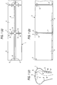
- Figs. 1(a), 1(b) and 1(c) are a front view, a plan view and a side view of a plate-like structure with a solar battery for a sound insulation wall, in which the structure is installed on the top end portion of the sound insulation wall in the form of a head board.
- a solar-battery-built-in plate-like body 1 is formed in such a manner that a substrate 2 formed from a hard plate-like material such as a steel plate or the like having a gentle convex arcuate portion, and a flexible amorphous silicon solar battery 3 are bonded and shaped with each other so that the solar battery 3 is made to cover the outer surface of the substrate 2.
- the top end portion of the plate-like body 1 is halved at its center, and the two divisions of the plate-like body 1 are connected to each other at their top end connection portions 4.
- the plate-like body 1 may be shaped into an integrated form without providing any top end connection portions 4.
- the halved portions of the plate-like body 1 are connected with each other symmetrically with respective to the top end connection portions 4, the shape is not limited to this, and there are no problems so long as the plate-like body 1 has a gentle convex arcuate portion having, for example, a semi-circular section, a semi-elliptic section, or the like, so that a flexible amorphous silicon solar battery can adhere thereto.
- the amorphous silicon solar battery 3 is made to adhere onto the whole surface of the substrate 2 basically, it may be made to adhere not onto the whole surface but partially on demands, with not-adhering portions left as they are, or in some case, the solar battery 3 may be covered with a transparent plate-like material such as an acrylic sheet or the like.
- the solar-battery-built-in plate-like body 1 can be coupled with another one through coupling connection portions 7, and may be coupled with further ones in accordance with the conditions of the installing place and the required quantity of electric energy.
- Electric connection portions 5 are connected to the amorphous silicon solar battery 3 at the circumferential edge portions of the solar-battery-built-in plate-like body 1 through fitting holes provided in the substrate 2 so that the electric connection portions 5 do not project over the circumferential edges of the plate-like body 1.
- electric connection portions 5 are provided by two, one in the right and the other one in the left, at the side of the coupling connection portions 7 on the circumferential edge portion of the solar-battery-built-in plate-like body 1.
- the divisions of the solar-battery-built-in plate-like body 1 opposite to each other in the right and left with respect to the top end connection portion 4 are connected to each other by respective wiring 6 through the electric connection portions 5, and the solar-battery-built-in plate-like bodies 1 coupled are connected to each other at the coupling connection portions 7 by respective wiring 6 through their electric connection portions 5 so that electricity generated in the respective solar batteries can be transmitted.
- the electric connection portions 5 may be integrated with the wiring 6 so that the integrated connection portions with the wiring can be removably attached to the solar-battery-built-in plate-like bodies 1.
- devices and/or circuits such as a booster circuit 50 or a secondary battery 51 can be provided through a wiring 8 extending from the electric connection portion 5 in accordance with necessity.
- a wiring 8 extending from the electric connection portion 5 in accordance with necessity.
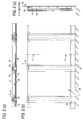
- Figs. 2(a)-2(c) show a second embodiment in which a solar-battery-built-in plate-like body 11 is inserted into a wall holding frame portion 10 made from a die steel material and erected at the edge of a road 9 such as a superhighway or the like so as to have also a function as sound insulation wall.
- the right and left edge portions of the solar-battery-built-in plate-like body 1 are sandwiched along their entire length between packing 12 for holding, damping, and absorbing thermal expansion, inserted into the wall holding frame body 10 from the above so as to be received by a lower frame portion 13, further held by a holding bracket 14, and then fixed by means of a set of bolt and nut 15.
- the thus inserted solar-battery-built-in plate-like body 11 has been worked in advance in such a shape that an amorphous silicon solar battery 16 is held by a pair of transparent plate-like materials 17 from its front and back surfaces before the plate-like body 11 is inserted, and two electric connection portions 18 are provided, that is, one on the right side of the upper portion and the other on the left side of the upper portion.
- the amorphous silicon solar battery 16 is used basically in such a manner that two such amorphous silicon solar batteries 16 are used in combination with their light receiving sides faced outside, only one amorphous silicon solar battery 16 may be used with its light receiving side faced only one direction toward a target in accordance with necessity.
- any plate-like material may be used so long as it has enough strength and transparency as a wall body.
- methacrylic resin plates in acrylic materials which are superior particularly in transparency, optical characteristics, weatherability and surface hardness, are adopted.
- the inserted solar-battery-built-in plate-like body 11 is electrically coupled with other adjacent solar-battery-built-in plate-like bodies 11 through wrings 19 extending from its electric connection portions 18 to the electric connection portions 18 of the latter, through through-holes 20 provided in the wall holding frame portions 10.
- Each electric connection portion 18 may be integrated with its wiring 19 so that the electric connection portion 18 with its wiring 19 may be removably attached to the solar-battery-built-in plate-like body 11.
- the quantity of generated electric energy may be adjusted in accordance with the conditions of the installation place and required quantity of electric energy.
- other solar batteries and/or apparatus and circuits such as a booster and a secondary battery may be incorporated on the extensions of wiring 21 connected to and led out from the electric connection portions 18, in accordance with necessity.
- a square concrete sound insulation wall 23 is mounted on the upper portion of a concrete balustrade 22 as a base erected at the edge of a superhighway or the like.
- the balustrade 22 and the concrete sound insulation wall 23 are fixed with each other by a bar 25 inserted into a through hole 24 provided vertically.
- a window-like opening portion which is rectangular and long in the vertical direction is provided in the vertical surface of the concrete sound insulation wall 23, and a frame groove 26 is provided in the circumferential edge of the window-like opening portion.
- the solar-battery-built-in plate-like body 27 has been worked in advance in such a shape that an amorphous silicon solar battery 28 is held by a pair of transparent plate-like materials 29 from its front and back surfaces and electric connection portions 30 are provided by two, that is, one on the right side of the upper portion and the other on the left side of the upper portion.
- the amorphous silicon solar battery 16 is used basically in such a manner that two such amorphous silicon solar batteries 16 are used in combination with their light receiving sides faced outside, only one amorphous silicon solar battery 16 may be used with its light receiving side faced only one direction toward a target in accordance with necessity.
- the transparent plate-like materials 29 any plate-like material may be used so long as it has enough strength and transparency as a wall body.
- methacrylic resin plates in acrylic materials which are superior particularly in transparency, optical characteristics, weatherability and surface hardness, are adopted.
- the solar-battery-built-in plate-like body 27 is inserted into the frame groove 26 provided in the circumferential edge of a window-like opening portion of the concrete sound insulation wall 23.
- the solar-battery-built-in plate-like body 27 is electrically coupled with other adjacent solar-battery-built-in plate-like bodies 27 through wiring 32 which are connected between an electric connection portion 30 of the former and the respective electric connection portions 30 of the latter, through through-holes 31 provided horizontally in the concrete sound insulation wall 23.
- Each electric connection portion 30 may be integrated with its wiring 32 so that the electric connection portion 30 with its wiring 32 may be removably attached to the solar-battery-built-in plate-like body 27.
- the quantity of generated electric energy may be adjusted in accordance with the conditions of the installation place and required quantity of electric energy.
- through holes 33 are provided in suitable places in the upper and lower portions of the vertical surface from the upper edge of the concrete sound insulation wall 23, so that another solar battery and/or apparatus and circuits such as a booster and a secondary battery may be incorporated on the extension of a wiring connected to the electric connection portion 30.
- a seal material, a packing and so on may be inserted into a gap between the inserted solar-battery-built-in plate-like body 27 and the frame groove 26 to thereby prevent rainwater from entering the gap, or to thereby hold the solar-battery-built-in plate-like body 27.
- Fig. 4 shows a fourth embodiment of a structure in which the respective embodiments in Figs. 1 and 2 are combined.
- the sound insulation wall structure in which the solar-battery-built-in plate-like body 11 is inserted into the wall holding frame portion 10 erected at the edge portion of the road 9 such as a superhighway or the like and made from a die steel material so as to provide also a function of a sound insulation wall as shown in Fig. 2, and the structure in which the solar-battery-built-in plate-like body 1 having a gentle convex arcuate portion and halved at the center of the top end portion is installed on the upper portion.
- the two structures are fixed with each other by bolts through a connecting bracket 34 in the lower end portion of the solar-battery-built-in plate-like body 1 and in the upper end portion of the wall holding frame portion 10.
- the wiring 8 led from the electric connection portion 5 of the solar-battery-built-in plate-like body 1 is connected to the electric connection portion 18 of the solar-battery-built-in plate-like body 11 so that the solar-battery-built-in plate-like bodies 1 and 11 are electrically coupled with each other.
- the lower end portion of the solar-battery-built-in plate-like body 1 in Fig. 1 installed on the upper portion may be fixed by means of screws to the upper end portion of the concrete sound insulation wall 23 shown in Fig. 3 through a connection body of the connection bracket 34 so that the two solar-battery-built-in plate-like bodies 1 and 27 are integrated with each other.
- the wiring 8 led from the electric connection portion 5 of the solar-battery-built-in plate-like body 1 is connected to the electric connection portion 30 of the solar-battery-built-in plate-like body 27 through the through hole 33 of the concrete sound insulation wall 23 so that the solar-battery-built-in plate-like bodies 1 and 27 are electrically coupled with each other.
- a solar battery structure having a high conversion efficiency can be used integrally with a sound insulation wall at a place having suitable solar battery installing conditions, such as the edge portion of a superhighway or the like, without particularly providing a new installation place. Accordingly, as a solar-battery-built-in structure for a sound insulation wall, the manufacturing cost and the installation cost can be reduced greatly.
- the respective solar batteries are integrated for a sound insulation wall, electric devices and/or circuits are internally provided, and the solar batteries are easily and removably connected through electric connection portions, so that the installation in the site can be performed in a short time and easily.
- the structure can be managed together with the sound insulation wall, so that examination can be performed easily and labor for maintenance can be reduced.
- the structure before the installation, the structure is shaped and prepared in advance in a factory in the form which is suitable for transportation as a solar-battery-built-in plate-like structure for a sound insulation wall, so that it can be removed and replaced easily when there arises a fault or damage. Further, in cleaning, the whole of the sound insulation wall including the portion of the solar batteries can be cleaned integrally and efficiently on the basis of the way of cleaning the sound insulation wall.
- the equipment in which solar-battery-built-in sound insulation wall structures are coupled with each other to be extended is used as a multi-purpose electric power supply system
- electricity can be supplied easily through a wiring from any place of the extended structures, so that the equipment can be used not only for an electric equipment of a superhighway or the like but also for supplying electric power to the area around the superhighway.
- this solar-battery-built-in sound insulation wall structure equipment can also be applied to a sound insulation wall in a high-speed railroad, a factory or the like where large noise is generated.
Applications Claiming Priority (2)
| Application Number | Priority Date | Filing Date | Title |
|---|---|---|---|
| JP154058/95 | 1995-05-30 | ||
| JP15405895A JP3644075B2 (ja) | 1995-05-30 | 1995-05-30 | 遮音壁用太陽電池付板状体構造 |
Publications (2)
| Publication Number | Publication Date |
|---|---|
| EP0746043A2 true EP0746043A2 (de) | 1996-12-04 |
| EP0746043A3 EP0746043A3 (de) | 1997-03-12 |
Family
ID=15575996
Family Applications (1)
| Application Number | Title | Priority Date | Filing Date |
|---|---|---|---|
| EP96108581A Withdrawn EP0746043A3 (de) | 1995-05-30 | 1996-05-30 | Plattenförmige Struktur mit Solarbatterie für eine Schallschutzwand |
Country Status (5)
| Country | Link |
|---|---|
| US (1) | US5741369A (de) |
| EP (1) | EP0746043A3 (de) |
| JP (1) | JP3644075B2 (de) |
| KR (1) | KR960041531A (de) |
| TW (1) | TW294744B (de) |
Cited By (4)
| Publication number | Priority date | Publication date | Assignee | Title |
|---|---|---|---|---|
| EP1172484A2 (de) * | 2000-07-12 | 2002-01-16 | Haitsma Beton B.V. | Leitplankenelement mit Schalldämmwand |
| CN101663438B (zh) * | 2007-05-08 | 2011-06-29 | 株式会社泰建 | 用于降低噪音的设备 |
| AT511155A1 (de) * | 2011-02-21 | 2012-09-15 | Sedelmayer Rainer Mag | Vorrichtung zur befestigung von photovoltaischen kollektoren |
| CN107181448A (zh) * | 2017-06-06 | 2017-09-19 | 深圳市奈士迪技术研发有限公司 | 一种便于安装的光伏发电设备 |
Families Citing this family (11)
| Publication number | Priority date | Publication date | Assignee | Title |
|---|---|---|---|---|
| US5880796A (en) * | 1996-07-12 | 1999-03-09 | Casio Computer Co., Ltd. | Display device with display plate having metal upper suface including narrow outgoing opening for emitting light from light emitting member |
| JP2900905B2 (ja) * | 1997-02-26 | 1999-06-02 | 日東紡績株式会社 | 遮音壁頂部の吸音材の取付構造と取付方法 |
| JP3789035B2 (ja) * | 1997-12-01 | 2006-06-21 | 東日本高速道路株式会社 | 開閉式分岐型遮音壁 |
| DE19906989A1 (de) * | 1999-02-19 | 2000-09-14 | Roehm Gmbh | Lärmschutzwandsegment |
| JP3576146B2 (ja) * | 2002-04-05 | 2004-10-13 | 沖電気工業株式会社 | 半導体装置 |
| TW200833918A (en) * | 2007-02-07 | 2008-08-16 | Univ Nat Taiwan Science Tech | Prefabricated wallboard and manufacture method and construction method thereof |
| KR100938734B1 (ko) * | 2009-09-03 | 2010-01-26 | 박재성 | 태양광 방음벽 |
| CN101892640A (zh) * | 2010-07-21 | 2010-11-24 | 上海耀江太阳能科技有限公司 | 一种带有太阳能模块的声屏障结构 |
| TWI413750B (zh) * | 2010-10-08 | 2013-11-01 | Nexpower Technology Corp | 太陽能電池面板及其安裝結構 |
| US9595254B1 (en) * | 2015-08-25 | 2017-03-14 | Acoustical Fulfillment LLC | Adaptive acoustical treatment assembly |
| US11489483B2 (en) | 2015-12-09 | 2022-11-01 | Brian Patrick Janowski | Solar window construction and methods |
Citations (5)
| Publication number | Priority date | Publication date | Assignee | Title |
|---|---|---|---|---|
| US4605813A (en) * | 1982-09-29 | 1986-08-12 | Nippondenso Co., Ltd. | Amorphous silicon solar battery |
| DE4219075A1 (de) * | 1992-06-11 | 1993-12-16 | Degussa | Schallschutzwand und Schallschutzelement |
| DE9318768U1 (de) * | 1993-12-08 | 1994-04-07 | Holzinger Juergen | Hochabsorbierende Lärmschutz-Photovoltaik-Elemente |
| US5329073A (en) * | 1993-02-09 | 1994-07-12 | Nitto Boseki Co., Ltd. | Sound absorbing device for sound insulation wall |
| JPH08120625A (ja) * | 1994-10-27 | 1996-05-14 | Sekisui Jushi Co Ltd | 道路用防音壁 |
Family Cites Families (13)
| Publication number | Priority date | Publication date | Assignee | Title |
|---|---|---|---|---|
| US4139399A (en) * | 1978-01-18 | 1979-02-13 | Solarex Corporation | Solar panel with removable cell matrix, and method of making same |
| US4582953A (en) * | 1983-06-24 | 1986-04-15 | Kyocera Corporation | Solar cell module |
| DE3528087C2 (de) * | 1984-08-06 | 1995-02-09 | Showa Aluminum Corp | Substrat für Solarzellen aus amorphem Silicium |
| DE3903521C2 (de) * | 1989-02-07 | 1993-11-25 | Kunert Heinz | Transparentes Element zur Verwendung als Fenster-, Wand, Dach- oder Brüstungselement |
| DE9017938U1 (de) * | 1990-09-20 | 1992-03-12 | Flachglas-Solartechnik Gmbh, 5000 Koeln, De | |
| JPH0673712A (ja) * | 1992-05-22 | 1994-03-15 | Ngk Insulators Ltd | 太陽電池付き防音壁 |
| JP2843742B2 (ja) * | 1993-09-06 | 1999-01-06 | 積水樹脂株式会社 | 防音壁 |
| JP2739553B2 (ja) * | 1994-01-26 | 1998-04-15 | フドウ建研株式会社 | 遮音壁構造及びその施工方法 |
| JP2707055B2 (ja) * | 1994-03-14 | 1998-01-28 | 日本道路公団 | 遮音壁上端に対する吸音体の取付方法 |
| JP2796509B2 (ja) * | 1995-01-30 | 1998-09-10 | 株式会社フジタ | 太陽電池パネル一体型遮音パネル |
| JPH08232214A (ja) * | 1995-02-24 | 1996-09-10 | Sekisui Jushi Co Ltd | 緑化防音壁 |
| JPH08253914A (ja) * | 1995-03-15 | 1996-10-01 | Fujita Corp | 太陽電池パネル一体型遮音パネル |
| JPH08253913A (ja) * | 1995-03-15 | 1996-10-01 | Fujita Corp | 太陽電池パネル一体型遮音パネル |
-
1995
- 1995-05-30 JP JP15405895A patent/JP3644075B2/ja not_active Expired - Fee Related
-
1996
- 1996-05-25 TW TW085106217A patent/TW294744B/zh active
- 1996-05-28 US US08/654,345 patent/US5741369A/en not_active Expired - Fee Related
- 1996-05-30 EP EP96108581A patent/EP0746043A3/de not_active Withdrawn
- 1996-05-30 KR KR19960018648A patent/KR960041531A/ko not_active Application Discontinuation
Patent Citations (5)
| Publication number | Priority date | Publication date | Assignee | Title |
|---|---|---|---|---|
| US4605813A (en) * | 1982-09-29 | 1986-08-12 | Nippondenso Co., Ltd. | Amorphous silicon solar battery |
| DE4219075A1 (de) * | 1992-06-11 | 1993-12-16 | Degussa | Schallschutzwand und Schallschutzelement |
| US5329073A (en) * | 1993-02-09 | 1994-07-12 | Nitto Boseki Co., Ltd. | Sound absorbing device for sound insulation wall |
| DE9318768U1 (de) * | 1993-12-08 | 1994-04-07 | Holzinger Juergen | Hochabsorbierende Lärmschutz-Photovoltaik-Elemente |
| JPH08120625A (ja) * | 1994-10-27 | 1996-05-14 | Sekisui Jushi Co Ltd | 道路用防音壁 |
Non-Patent Citations (2)
| Title |
|---|
| PATENT ABSTRACTS OF JAPAN vol. 96, no. 9, 30 September 1996 & JP-A-08 120625 (SEKISUI JUSHI CO. LTD.), 14 May 1996, * |
| SYMPOSIUM ON AMORPHOUS SILICON TECHNOLOGY 1995, 18 - 21 April 1995, SAN FRANCISCO, CALIFORNIA, USA, pages 609-619, XP002021854 S. FUJIKAKE ET AL.: "Flexible a-Si ssolar cells with plastic film substrate" * |
Cited By (8)
| Publication number | Priority date | Publication date | Assignee | Title |
|---|---|---|---|---|
| EP1172484A2 (de) * | 2000-07-12 | 2002-01-16 | Haitsma Beton B.V. | Leitplankenelement mit Schalldämmwand |
| NL1016913C2 (nl) * | 2000-07-12 | 2002-01-17 | Dla & Landscape Architects B V | Afscheidingselement met geluidwand. |
| EP1172484A3 (de) * | 2000-07-12 | 2003-10-29 | Haitsma Beton B.V. | Leitplankenelement mit Schalldämmwand |
| CN101663438B (zh) * | 2007-05-08 | 2011-06-29 | 株式会社泰建 | 用于降低噪音的设备 |
| AT511155A1 (de) * | 2011-02-21 | 2012-09-15 | Sedelmayer Rainer Mag | Vorrichtung zur befestigung von photovoltaischen kollektoren |
| AT511155B1 (de) * | 2011-02-21 | 2013-01-15 | Sedelmayer Rainer Mag | Vorrichtung zur befestigung von photovoltaischen kollektoren |
| CN107181448A (zh) * | 2017-06-06 | 2017-09-19 | 深圳市奈士迪技术研发有限公司 | 一种便于安装的光伏发电设备 |
| CN107181448B (zh) * | 2017-06-06 | 2019-03-22 | 济宁中科先进技术研究院有限公司 | 一种便于安装的光伏发电设备 |
Also Published As
| Publication number | Publication date |
|---|---|
| JP3644075B2 (ja) | 2005-04-27 |
| KR960041531A (de) | 1996-12-19 |
| US5741369A (en) | 1998-04-21 |
| TW294744B (de) | 1997-01-01 |
| JPH08326019A (ja) | 1996-12-10 |
| EP0746043A3 (de) | 1997-03-12 |
Similar Documents
| Publication | Publication Date | Title |
|---|---|---|
| EP0746043A2 (de) | Plattenförmige Struktur mit Solarbatterie für eine Schallschutzwand | |
| US7102074B2 (en) | Photovoltaic attachment system | |
| WO2018159866A1 (ko) | 부유식 태양광 발전장치 | |
| JP3326207B2 (ja) | 太陽電池モジュール | |
| JP2001152619A (ja) | 太陽電池パネルの支持構造 | |
| CN211007204U (zh) | 一种双面太阳能发电隔音组件 | |
| KR20000025876A (ko) | 태양 전지 프레임 고정 구조 | |
| JP2006140420A (ja) | 太陽電池モジュール及び設置構造 | |
| KR20130027244A (ko) | 태양광발전이 가능한 방음벽 | |
| KR102580644B1 (ko) | 태양 전지 모듈 및 이를 포함하는 태양광 발전 시스템 | |
| CN111697462A (zh) | 一种装配式变电站主变室隔音降噪模块 | |
| CN209001888U (zh) | 光伏模块单元及光伏装置 | |
| JP2000064555A (ja) | 太陽電池の取付構造 | |
| CN108521251A (zh) | 光伏模块单元及光伏装置 | |
| JPH08199512A (ja) | 太陽電池パネル一体型遮音パネル | |
| CN218149112U (zh) | 一种新型光电玻璃幕墙 | |
| CN213176315U (zh) | 一种便于携带和运输的太阳能光伏板 | |
| CN219760463U (zh) | 一种配电网可扩展式环网箱 | |
| CN218734012U (zh) | 太阳能板安装装置 | |
| CN216721260U (zh) | 一种光伏阵列安装结构及配备该结构的光伏发电系统 | |
| CN219740040U (zh) | 基于新能源的高速公路etc门架应急供电系统 | |
| JPH08253914A (ja) | 太陽電池パネル一体型遮音パネル | |
| CN111425353B (zh) | 一种风力发电机组后机架总成 | |
| CN212381171U (zh) | 一种安装方便安全的太阳能板 | |
| CN209001887U (zh) | 光伏模块单元及光伏装置 |
Legal Events
| Date | Code | Title | Description |
|---|---|---|---|
| PUAI | Public reference made under article 153(3) epc to a published international application that has entered the european phase |
Free format text: ORIGINAL CODE: 0009012 |
|
| AK | Designated contracting states |
Kind code of ref document: A2 Designated state(s): DE FR GB |
|
| PUAL | Search report despatched |
Free format text: ORIGINAL CODE: 0009013 |
|
| AK | Designated contracting states |
Kind code of ref document: A3 Designated state(s): DE FR GB |
|
| 17P | Request for examination filed |
Effective date: 19970424 |
|
| STAA | Information on the status of an ep patent application or granted ep patent |
Free format text: STATUS: THE APPLICATION HAS BEEN WITHDRAWN |
|
| 18W | Application withdrawn |
Effective date: 20070321 |