EP0745824A1 - Heat exchanger and method for manufacturing the same - Google Patents
Heat exchanger and method for manufacturing the same Download PDFInfo
- Publication number
- EP0745824A1 EP0745824A1 EP96107822A EP96107822A EP0745824A1 EP 0745824 A1 EP0745824 A1 EP 0745824A1 EP 96107822 A EP96107822 A EP 96107822A EP 96107822 A EP96107822 A EP 96107822A EP 0745824 A1 EP0745824 A1 EP 0745824A1
- Authority
- EP
- European Patent Office
- Prior art keywords
- tank
- fluid pipe
- pipe
- fluid
- end portion
- Prior art date
- Legal status (The legal status is an assumption and is not a legal conclusion. Google has not performed a legal analysis and makes no representation as to the accuracy of the status listed.)
- Granted
Links
- 238000000034 method Methods 0.000 title claims description 14
- 238000004519 manufacturing process Methods 0.000 title claims description 11
- 239000012530 fluid Substances 0.000 claims abstract description 124
- 238000005219 brazing Methods 0.000 claims abstract description 42
- 238000003780 insertion Methods 0.000 claims abstract description 28
- 230000037431 insertion Effects 0.000 claims abstract description 28
- 239000000463 material Substances 0.000 claims abstract description 26
- 238000007599 discharging Methods 0.000 claims abstract description 7
- 238000005452 bending Methods 0.000 claims abstract description 6
- 238000010438 heat treatment Methods 0.000 description 4
- 239000003507 refrigerant Substances 0.000 description 2
- 230000015572 biosynthetic process Effects 0.000 description 1
- 238000012986 modification Methods 0.000 description 1
- 230000004048 modification Effects 0.000 description 1
- 238000005192 partition Methods 0.000 description 1
- 238000003825 pressing Methods 0.000 description 1
- 238000004080 punching Methods 0.000 description 1
- 238000003466 welding Methods 0.000 description 1
Images


Classifications
-
- F—MECHANICAL ENGINEERING; LIGHTING; HEATING; WEAPONS; BLASTING
- F28—HEAT EXCHANGE IN GENERAL
- F28F—DETAILS OF HEAT-EXCHANGE AND HEAT-TRANSFER APPARATUS, OF GENERAL APPLICATION
- F28F9/00—Casings; Header boxes; Auxiliary supports for elements; Auxiliary members within casings
- F28F9/02—Header boxes; End plates
- F28F9/04—Arrangements for sealing elements into header boxes or end plates
- F28F9/16—Arrangements for sealing elements into header boxes or end plates by permanent joints, e.g. by rolling
-
- B—PERFORMING OPERATIONS; TRANSPORTING
- B21—MECHANICAL METAL-WORKING WITHOUT ESSENTIALLY REMOVING MATERIAL; PUNCHING METAL
- B21D—WORKING OR PROCESSING OF SHEET METAL OR METAL TUBES, RODS OR PROFILES WITHOUT ESSENTIALLY REMOVING MATERIAL; PUNCHING METAL
- B21D39/00—Application of procedures in order to connect objects or parts, e.g. coating with sheet metal otherwise than by plating; Tube expanders
- B21D39/06—Application of procedures in order to connect objects or parts, e.g. coating with sheet metal otherwise than by plating; Tube expanders of tubes in openings, e.g. rolling-in
-
- B—PERFORMING OPERATIONS; TRANSPORTING
- B21—MECHANICAL METAL-WORKING WITHOUT ESSENTIALLY REMOVING MATERIAL; PUNCHING METAL
- B21D—WORKING OR PROCESSING OF SHEET METAL OR METAL TUBES, RODS OR PROFILES WITHOUT ESSENTIALLY REMOVING MATERIAL; PUNCHING METAL
- B21D53/00—Making other particular articles
- B21D53/02—Making other particular articles heat exchangers or parts thereof, e.g. radiators, condensers fins, headers
-
- F—MECHANICAL ENGINEERING; LIGHTING; HEATING; WEAPONS; BLASTING
- F28—HEAT EXCHANGE IN GENERAL
- F28F—DETAILS OF HEAT-EXCHANGE AND HEAT-TRANSFER APPARATUS, OF GENERAL APPLICATION
- F28F9/00—Casings; Header boxes; Auxiliary supports for elements; Auxiliary members within casings
- F28F9/02—Header boxes; End plates
- F28F9/0246—Arrangements for connecting header boxes with flow lines
- F28F9/0248—Arrangements for sealing connectors to header boxes
-
- F—MECHANICAL ENGINEERING; LIGHTING; HEATING; WEAPONS; BLASTING
- F28—HEAT EXCHANGE IN GENERAL
- F28F—DETAILS OF HEAT-EXCHANGE AND HEAT-TRANSFER APPARATUS, OF GENERAL APPLICATION
- F28F9/00—Casings; Header boxes; Auxiliary supports for elements; Auxiliary members within casings
- F28F9/02—Header boxes; End plates
- F28F9/04—Arrangements for sealing elements into header boxes or end plates
- F28F9/16—Arrangements for sealing elements into header boxes or end plates by permanent joints, e.g. by rolling
- F28F9/18—Arrangements for sealing elements into header boxes or end plates by permanent joints, e.g. by rolling by welding
- F28F9/182—Arrangements for sealing elements into header boxes or end plates by permanent joints, e.g. by rolling by welding the heat-exchange conduits having ends with a particular shape, e.g. deformed; the heat-exchange conduits or end plates having supplementary joining means, e.g. abutments
-
- F—MECHANICAL ENGINEERING; LIGHTING; HEATING; WEAPONS; BLASTING
- F28—HEAT EXCHANGE IN GENERAL
- F28F—DETAILS OF HEAT-EXCHANGE AND HEAT-TRANSFER APPARATUS, OF GENERAL APPLICATION
- F28F2275/00—Fastening; Joining
- F28F2275/12—Fastening; Joining by methods involving deformation of the elements
- F28F2275/122—Fastening; Joining by methods involving deformation of the elements by crimping, caulking or clinching
-
- Y—GENERAL TAGGING OF NEW TECHNOLOGICAL DEVELOPMENTS; GENERAL TAGGING OF CROSS-SECTIONAL TECHNOLOGIES SPANNING OVER SEVERAL SECTIONS OF THE IPC; TECHNICAL SUBJECTS COVERED BY FORMER USPC CROSS-REFERENCE ART COLLECTIONS [XRACs] AND DIGESTS
- Y10—TECHNICAL SUBJECTS COVERED BY FORMER USPC
- Y10T—TECHNICAL SUBJECTS COVERED BY FORMER US CLASSIFICATION
- Y10T29/00—Metal working
- Y10T29/49—Method of mechanical manufacture
- Y10T29/4935—Heat exchanger or boiler making
- Y10T29/49377—Tube with heat transfer means
- Y10T29/49378—Finned tube
-
- Y—GENERAL TAGGING OF NEW TECHNOLOGICAL DEVELOPMENTS; GENERAL TAGGING OF CROSS-SECTIONAL TECHNOLOGIES SPANNING OVER SEVERAL SECTIONS OF THE IPC; TECHNICAL SUBJECTS COVERED BY FORMER USPC CROSS-REFERENCE ART COLLECTIONS [XRACs] AND DIGESTS
- Y10—TECHNICAL SUBJECTS COVERED BY FORMER USPC
- Y10T—TECHNICAL SUBJECTS COVERED BY FORMER US CLASSIFICATION
- Y10T29/00—Metal working
- Y10T29/49—Method of mechanical manufacture
- Y10T29/4935—Heat exchanger or boiler making
- Y10T29/49391—Tube making or reforming
Definitions
- the present invention relates to heat exchangers and a method for manufacturing the same, and more particularly to an improved connection structure and connection method between a tank and a fluid pipe for heat exchangers.
- FIG. 9 depicts a heat exchanger tank 104 having a pipe insertion hole 102 disposed in tank wall 103 of tank 104.
- a burr 101 may be formed around pipe insertion hole 102 to increase the surface area of tank 104 contacting fluid pipe 105, i.e., to enlarge the brazing area between tank 104 and fluid pipe 105.
- An end portion of fluid pipe 105 may be inserted into pipe insertion hole 102 so that a tip 110 of fluid pipe 105 may be positioned over a tip 111 of burr 101.
- the inserted fluid pipe 105 may be temporarily fixed to tank 104 by spot welding 106.
- Annular brazing material 107 may be placed around the periphery of fluid pipe 105 and brought into contact with an outer surface 108 of tank wall 103. Then, the assembly may be is heated in a furnace, whereby fluid pipe 105 is brazed to tank 104.
- annular brazing material 107 may shift away from outer surface 108 of tank wall 103. If shifting occurs, an insufficient amount of molten brazing material may remain in contact with burr 101 and fluid pipe 105 to form a good brazed and connected state between fluid pipe 105 and tank 104.
- portion of fluid pipe 105 inserted into the interior of tank 104 is often relatively long. Consequently, the portion disrupts fluid flow in tank 104 resulting in significant pressure loss of fluid flow in the tank 104.
- the contact area, i.e. , brazing area, between tank 104 and fluid pipe 105 is relatively small. Hence, the connection strength between fluid pipe 105 and tank 104 may be insufficient.
- a heat exchanger having a connection structure between a tank and a fluid pipe according to the present invention.
- a heat exchanger according to the present invention comprises a tank including a tank wall having a pipe insertion hole disposed in the tank wall.
- a fluid pipe may be connected to the tank wall for introducing a fluid into the tank or discharging a fluid from the tank.
- the tank wall may have a burr formed around the pipe insertion hole extending toward an interior of the tank.
- the fluid pipe may have a flange formed on a periphery of the fluid pipe by, for example, bending the fluid pipe onto itself. An end portion of the fluid pipe is inserted into the pipe insertion hole so that the flange contacts an outer surface of the tank wall. The inserted end portion of the fluid pipe is outwardly expanded and caulked together with the burr.
- a method for manufacturing a heat exchanger comprises the steps of forming a burr extending toward an interior of a tank around a pipe insertion hole disposed in a tank wall of the tank, forming a flange on a periphery of a fluid pipe by, for example, bending the fluid pipe onto itself, inserting an end portion of the fluid pipe into the pipe insertion hole so that the flange contacts an outer surface of the tank wall, and expanding and caulking the inserted end portion of the fluid pipe together with the burr.
- an annular brazing material may be placed on the periphery of the fluid pipe before insertion of the fluid pipe into the pipe insertion hole so that the annular brazing material engages the flange.
- the position of the annular brazing material may always be maintained at a desired position during heating, even if vibrations occur on the assembly.
- a sufficient amount of molten brazing material may be supplied to the connection portion between the fluid pipe and the tank wall, thereby ensuring a good brazed state.
- the inserted end portion of the fluid pipe is expanded and caulked together with the burr, the length of the fluid pipe inserted into the interior of the tank may be minimized. Therefore, the pressure loss in the tank originating from the inserted portion of the fluid pipe into the tank may be minimized as compared with the conventional structure.
- the flange contacts the outer surface of the tank wall and the inserted end portion of the fluid pipe contacts the burr formed on the tank wall, the contact area between the fluid pipe and the tank may be increased. Therefore, the connection strength therebetween and the brazing strength therebetween may also be increased.
- the fluid pipe may be securely fixed to the tank.
- the end opposite from the inserted end of the fluid pipe (a fluid introducing port or a fluid discharging port) may be precisely positioned before brazing. Therefore, a temporary fixing between the fluid pipe and the tank before brazing is not necessary, and a fixing during brazing such as one using a fixing jig is also unnecessary. As a result, the manufacturing process may be simplified, and the cost for the manufacture may be reduced.
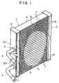
- Fig. 1 is a perspective view of a heat exchanger according to an embodiment of the present invention.
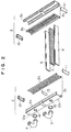
- Fig. 2 is an exploded perspective view of the heat exchanger depicted in Fig. 1.
- Fig. 3 is an enlarged elevational view of part of the heat exchanger depicted in Fig. 1.
- Fig. 4 is an enlarged vertical sectional view of a connection portion between a fluid pipe and a tank wall of the heat exchanger depicted in Fig. 1.
- Fig. 5 is an enlarged vertical sectional view of the connection portion between the fluid pipe and the tank wall of the heat exchanger depicted in Fig. 1 and depicts a method for expanding and caulking an end portion of the fluid pipe together with a burr of the tank wall according to another embodiment of the present invention.
- Fig. 6 is an enlarged vertical sectional view of the connection portion between the fluid pipe and the tank wall of the heat exchanger depicted in Fig. 1 prior to brazing.
- Fig. 7 is a vertical sectional view of part of a connection portion between a fluid pipe and a tank wall of a heat exchanger according to another embodiment of the present invention.
- Fig. 8 is a vertical sectional view of part of a connection portion between a fluid pipe and a tank wall of a heat exchanger according to another embodiment of the present invention.
- Fig. 9 is a vertical sectional view of part of a connection portion between a fluid pipe and a tank wall of a conventional heat exchanger.
- Heat exchanger 1 includes a pair of tanks 2 and 3. Each of tanks 2 and 3 may be constructed from tank member 2a or 3a and seat member 2b or 3b to form barrel 2c or 3c.
- Inlet pipe 4 and outlet pipe 5 may be provided as fluid pipes for introducing a fluid (for example, refrigerant) into tank 2 and discharging the fluid from tank 2, respectively.
- Inlet pipe 4 and outlet pipe 5 may be connected to tank 2 by brazing.
- a plurality of flat heat transfer tubes 6 (for example, refrigerant tubes) may be fluidly interconnected between tanks 2 and 3.
- Corrugated fins 7 may be disposed on either or both surfaces of each heat transfer tube 6.
- Each of tanks 2 and 3 may be closed at both longitudinal ends by caps 10 and 11, respectively.
- the interior of tank 2 may be divided into two sections 12a and 12b by partition 13 provided in tank 2.
- inlet pipe 4 and outlet pipe 5 may be connected to pipe insertion holes 14 and 15, respectively defined on tank member 2a of tank 2.
- the other ends of inlet pipe 4 and outlet pipe 5 form open ends 4a or 5a and function as a fluid introducing port or a fluid discharging port, as shown in Figs. 2 and 3.
- Inlet pipe 4 and outlet pipe 5 may be connected to tank 2 as follows. For purposes of explanation, connection of inlet pipe 4 will be described. Outlet pipe 5 may also be connected in the following manner.
- the term fluid pipe may refer to either inlet pipe 4 or outlet pipe 5.
- Tank member 2a has a tank wall on which pipe insertion holes 14 and 15 are defined. As depicted in Figs. 4-6, a burr 17 may be formed around pipe insertion hole 14 to extend toward the interior of tank 2.
- a flange 4b may be formed on the periphery of fluid pipe 4 near end portion 4c of fluid pipe 4. Flange 4b may be formed by bending fluid pipe 4 onto itself so a flange formation portion protrudes outwardly in the axial direction. Other methods of forming flange 4b may also be used. End portion 4c of fluid pipe 4 may be inserted through pipe insertion hole 14 extending toward the interior of tank 2.
- annular brazing material 18 is placed around the periphery of end portion 4c of fluid pipe 4 so that annular brazing material 18 is brought into contact with flange 4b.
- Annular brazing material 18 may have an inner diameter smaller than an outer diameter of flange 4b.
- annular brazing material 18 may have a trapezoidal cross section.
- end portion 4c of fluid pipe 4 may be inserted into pipe insertion hole 14 until flange 4b is brought into contact with the outer surface of tank wall 16, as depicted in Fig. 5.
- the inserted end portion 4c of fluid pipe 4 extends over tip 30 of burr 17.
- tank member 2a (tank wall 16), fluid pipe 4 and annular brazing material 18 may be supported from the underside by lower jig 19.
- Punch 20 may be pressed from the upper side onto the inserted end portion 4c of fluid pipe 4.
- Punch 20 may have an annular caulking portion 20a formed as a curved recessed portion.
- End portion 4c of fluid pipe 4 may be caulked together with burr 17 by the dowmward pressing of punch 20.
- end portion 4c and burr 17 expand to open outwardly and become caulked to the surface of tank wall 16.
- End portion 4c is caulked so that the upper surface of end portion 4c is curved along caulking portion 20a of punch 20.
- the surface of the caulked end portion 4c facing the interior of tank 2 is formed as a curved surface convex toward the interior of tank 2.
- Such punching and caulking may be possible during manufacture because tank member 2a and seat member 2b of tank 2 are separate structures.
- fluid pipe 4 is fixed to tank wall 16 by caulked end portion 4c and to flange 4b by caulked burr 17.
- a tapered portion 25 of annular brazing material 18 may be provided.
- the taperd portion 25 may have a trapezoidal cross section and may be fixed between the outer surface of tank wall 16 and flange 4b.
- annular brazing material 18 is securely fixed between flange 4b and tank wall 16 before brazing, when the assembly is heated and brazed, the fixed annular brazing material 18 does not shift from the desired position during heating in a furnace, even if vibration occurs. Therefore, a sufficient amount of molten brazing material is always supplied to the connection portion between fluid pipe 4 and tank wall 16, and a good brazing state is achieved therebetween. A strong connection between fluid pipe 4 and tank wall 16 is thereby ensured.
- inserted end portion 4c of fluid pipe 4 is outwardly expanded and caulked together with burr 17, the insertion length of end portion 4c of fluid pipe 4 in a direction toward the interior of tank 2 may be minimized. Therefore, any pressure loss in tank 2 caused by the inserted end portion 4c may be minimized as compared with the conventional structure.
- flange 4b of fluid pipe 4 comes into contact with the outer surface of tank wall 16 and caulked end portion 4c of fluid pipe 4 comes into contact with the surface of caulked burr 17 formed on tank wall. Therefore, fluid pipe 4 comes into contact with tank wall 16 over a sufficiently broad contact area, thereby further increasing the connection strength between fluid pipe 4 and tank wall 16.
- end portion 4c of fluid pipe 4 is caulked together with burr 17 so that the caulked surface is formed as a curved surface convex toward the interior of tank 2. Therefore, the pressure loss in tank 2 may be minimized as compared with, for example, a concave curved surface.
- end portion 4c of fluid pipe 4 may be inserted into pipe connection hole 14 so as to extend over tip 30 of burr 17. Also, the inserted end portion 4c is caulked together with burr 17. Therefore, fluid pipe 4 may be extremely securely fixed to tank wall 16. As a result, when heated and brazed, the fluid pipe 4, particularly, fluid introducing port 4a, may be positioned and maintained at a desired position relative to tank member 2a without fixing fluid pipe 4 to tank member 2a using a specified jig. As a result, the manufacturing process may be simplified and the cost for manufacturing heat exchanger 1 may be reduced.
- annular brazing material may have a trapezoidal cross section in the above-described embodiment, the cross-sectional shape is not particularly restricted.
- annular brazing material 21 having a triangular cross section before caulking may be employed according to another embodiment depicted in Fig. 7.
- annular brazing material 22 having a rectangular cross section before caulking may be employed according to yet another embodiment depicted in Fig. 8.
Landscapes
- Engineering & Computer Science (AREA)
- Mechanical Engineering (AREA)
- Physics & Mathematics (AREA)
- Thermal Sciences (AREA)
- General Engineering & Computer Science (AREA)
- Details Of Heat-Exchange And Heat-Transfer (AREA)
Abstract
Description
- The present invention relates to heat exchangers and a method for manufacturing the same, and more particularly to an improved connection structure and connection method between a tank and a fluid pipe for heat exchangers.
- In a conventional heat exchanger having a tank and a fluid pipe connected to the tank, for example, a fluid inlet pipe or outlet pipe, brazing between the tank and the fluid pipe may be performed as follows. For example, Fig. 9 depicts a
heat exchanger tank 104 having apipe insertion hole 102 disposed intank wall 103 oftank 104. Aburr 101 may be formed aroundpipe insertion hole 102 to increase the surface area oftank 104 contactingfluid pipe 105, i.e., to enlarge the brazing area betweentank 104 andfluid pipe 105. An end portion offluid pipe 105 may be inserted intopipe insertion hole 102 so that atip 110 offluid pipe 105 may be positioned over a tip 111 ofburr 101. The insertedfluid pipe 105 may be temporarily fixed totank 104 byspot welding 106. Annularbrazing material 107 may be placed around the periphery offluid pipe 105 and brought into contact with anouter surface 108 oftank wall 103. Then, the assembly may be is heated in a furnace, wherebyfluid pipe 105 is brazed to tank 104. - In such a conventional connecting and brazing structure, when the assembly is heated in a furnace, if any vibration occurs, annular
brazing material 107 may shift away fromouter surface 108 oftank wall 103. If shifting occurs, an insufficient amount of molten brazing material may remain in contact withburr 101 andfluid pipe 105 to form a good brazed and connected state betweenfluid pipe 105 andtank 104. - Further, the portion of
fluid pipe 105 inserted into the interior oftank 104 is often relatively long. Consequently, the portion disrupts fluid flow intank 104 resulting in significant pressure loss of fluid flow in thetank 104. - Furthermore, the contact area, i.e., brazing area, between
tank 104 andfluid pipe 105 is relatively small. Hence, the connection strength betweenfluid pipe 105 andtank 104 may be insufficient. - Accordingly, it is an object of the present invention to provide a heat exchanger having a connection structure between a tank and a fluid pipe which can prevent undesired shifting of an annular brazing material during heating in a furnace, even if vibrations occur to the tank and fluid pipe assembly.
- It is another object of the present invention to provide a method for manufacturing such a heat exchanger.
- It is a further object of the present invention to minimize the length of a fluid pipe which is inserted into an interior of a tank, thereby minimizing pressure loss in the tank.
- It is a still further object of the present invention to increase the contact area between a tank and a fluid pipe, thereby increasing the connection strength resulting from brazing therebetween.
- These and other objects are achieved by a heat exchanger having a connection structure between a tank and a fluid pipe according to the present invention. A heat exchanger according to the present invention comprises a tank including a tank wall having a pipe insertion hole disposed in the tank wall. A fluid pipe may be connected to the tank wall for introducing a fluid into the tank or discharging a fluid from the tank. The tank wall may have a burr formed around the pipe insertion hole extending toward an interior of the tank. The fluid pipe may have a flange formed on a periphery of the fluid pipe by, for example, bending the fluid pipe onto itself. An end portion of the fluid pipe is inserted into the pipe insertion hole so that the flange contacts an outer surface of the tank wall. The inserted end portion of the fluid pipe is outwardly expanded and caulked together with the burr.
- A method for manufacturing a heat exchanger according to the present invention comprises the steps of forming a burr extending toward an interior of a tank around a pipe insertion hole disposed in a tank wall of the tank, forming a flange on a periphery of a fluid pipe by, for example, bending the fluid pipe onto itself, inserting an end portion of the fluid pipe into the pipe insertion hole so that the flange contacts an outer surface of the tank wall, and expanding and caulking the inserted end portion of the fluid pipe together with the burr.
- In such a heat exchanger and a method for manufacturing the same according to the present invention, because the flange is formed on the periphery of the fluid pipe, an annular brazing material may be placed on the periphery of the fluid pipe before insertion of the fluid pipe into the pipe insertion hole so that the annular brazing material engages the flange. Thereby, when the end portion of the fluid pipe is inserted into the pipe insertion hole and the flange is brought into contact with the outer surface of the tank wall, the annular brazing material may be securely fixed between the flange and the tank wall. Moreover, because the fluid pipe and the tank are heated and brazed in a furnace in the described assembly, the position of the annular brazing material may always be maintained at a desired position during heating, even if vibrations occur on the assembly. As a result, a sufficient amount of molten brazing material may be supplied to the connection portion between the fluid pipe and the tank wall, thereby ensuring a good brazed state.
- Moreover, because the inserted end portion of the fluid pipe is expanded and caulked together with the burr, the length of the fluid pipe inserted into the interior of the tank may be minimized. Therefore, the pressure loss in the tank originating from the inserted portion of the fluid pipe into the tank may be minimized as compared with the conventional structure.
- Further, because the flange contacts the outer surface of the tank wall and the inserted end portion of the fluid pipe contacts the burr formed on the tank wall, the contact area between the fluid pipe and the tank may be increased. Therefore, the connection strength therebetween and the brazing strength therebetween may also be increased.
- Furthermore, because the inserted end portion of the fluid pipe is caulked together with the burr such that the inserted end portion of the fluid pipe extends over and is caulked together with the burr, the fluid pipe may be securely fixed to the tank. Also, the end opposite from the inserted end of the fluid pipe (a fluid introducing port or a fluid discharging port) may be precisely positioned before brazing. Therefore, a temporary fixing between the fluid pipe and the tank before brazing is not necessary, and a fixing during brazing such as one using a fixing jig is also unnecessary. As a result, the manufacturing process may be simplified, and the cost for the manufacture may be reduced.
- Further objects, features, and advantages of the present invention will be understood from the detailed description of the preferred embodiments of the present invention with reference to the appropriate figures.
- Some preferred exemplary embodiments of the present invention will now be described with reference to the appropriate figures, which are given by way of example only, and are not intended to limit the present invention.
- Fig. 1 is a perspective view of a heat exchanger according to an embodiment of the present invention.
- Fig. 2 is an exploded perspective view of the heat exchanger depicted in Fig. 1.
- Fig. 3 is an enlarged elevational view of part of the heat exchanger depicted in Fig. 1.
- Fig. 4 is an enlarged vertical sectional view of a connection portion between a fluid pipe and a tank wall of the heat exchanger depicted in Fig. 1.
- Fig. 5 is an enlarged vertical sectional view of the connection portion between the fluid pipe and the tank wall of the heat exchanger depicted in Fig. 1 and depicts a method for expanding and caulking an end portion of the fluid pipe together with a burr of the tank wall according to another embodiment of the present invention.
- Fig. 6 is an enlarged vertical sectional view of the connection portion between the fluid pipe and the tank wall of the heat exchanger depicted in Fig. 1 prior to brazing.
- Fig. 7 is a vertical sectional view of part of a connection portion between a fluid pipe and a tank wall of a heat exchanger according to another embodiment of the present invention.
- Fig. 8 is a vertical sectional view of part of a connection portion between a fluid pipe and a tank wall of a heat exchanger according to another embodiment of the present invention.
- Fig. 9 is a vertical sectional view of part of a connection portion between a fluid pipe and a tank wall of a conventional heat exchanger.
- Referring to Figs. 1 and 2, a
heat exchanger 1 is provided according to an embodiment of the present invention.Heat exchanger 1 includes a pair oftanks tanks tank member 2a or 3a andseat member barrel Inlet pipe 4 andoutlet pipe 5 may be provided as fluid pipes for introducing a fluid (for example, refrigerant) intotank 2 and discharging the fluid fromtank 2, respectively.Inlet pipe 4 andoutlet pipe 5 may be connected totank 2 by brazing. A plurality of flat heat transfer tubes 6 (for example, refrigerant tubes) may be fluidly interconnected betweentanks Corrugated fins 7 may be disposed on either or both surfaces of eachheat transfer tube 6.Side members 8 and 9 may be provided on the upper surface of theuppermost fin 7a and on the lower surface of thelowermost fin 7b, respectively. Each oftanks caps 10 and 11, respectively. The interior oftank 2 may be divided into twosections partition 13 provided intank 2. - One end of
inlet pipe 4 andoutlet pipe 5 may be connected to pipe insertion holes 14 and 15, respectively defined on tank member 2a oftank 2. The other ends ofinlet pipe 4 andoutlet pipe 5 form open ends 4a or 5a and function as a fluid introducing port or a fluid discharging port, as shown in Figs. 2 and 3. -
Inlet pipe 4 andoutlet pipe 5 may be connected totank 2 as follows. For purposes of explanation, connection ofinlet pipe 4 will be described.Outlet pipe 5 may also be connected in the following manner. The term fluid pipe may refer to eitherinlet pipe 4 oroutlet pipe 5. - Tank member 2a has a tank wall on which pipe insertion holes 14 and 15 are defined. As depicted in Figs. 4-6, a
burr 17 may be formed aroundpipe insertion hole 14 to extend toward the interior oftank 2. Aflange 4b may be formed on the periphery offluid pipe 4 nearend portion 4c offluid pipe 4.Flange 4b may be formed by bendingfluid pipe 4 onto itself so a flange formation portion protrudes outwardly in the axial direction. Other methods of formingflange 4b may also be used.End portion 4c offluid pipe 4 may be inserted throughpipe insertion hole 14 extending toward the interior oftank 2. - Before
end portion 4c offluid pipe 4 is inserted intopipe insertion hole 14,annular brazing material 18 is placed around the periphery ofend portion 4c offluid pipe 4 so thatannular brazing material 18 is brought into contact withflange 4b.Annular brazing material 18 may have an inner diameter smaller than an outer diameter offlange 4b. In this embodiment,annular brazing material 18 may have a trapezoidal cross section. In such a condition,end portion 4c offluid pipe 4 may be inserted intopipe insertion hole 14 untilflange 4b is brought into contact with the outer surface oftank wall 16, as depicted in Fig. 5. The insertedend portion 4c offluid pipe 4 extends overtip 30 ofburr 17. The assembly of tank member 2a (tank wall 16),fluid pipe 4 andannular brazing material 18 may be supported from the underside bylower jig 19.Punch 20 may be pressed from the upper side onto the insertedend portion 4c offluid pipe 4.Punch 20 may have anannular caulking portion 20a formed as a curved recessed portion.End portion 4c offluid pipe 4 may be caulked together withburr 17 by the dowmward pressing ofpunch 20. When punch 20 presses down onend portion 4c offluid pipe 4 andburr 17,end portion 4c andburr 17 expand to open outwardly and become caulked to the surface oftank wall 16.End portion 4c is caulked so that the upper surface ofend portion 4c is curved alongcaulking portion 20a ofpunch 20. In other words, the surface of the caulkedend portion 4c facing the interior oftank 2 is formed as a curved surface convex toward the interior oftank 2. Such punching and caulking may be possible during manufacture because tank member 2a andseat member 2b oftank 2 are separate structures. - By the above-described caulking, as depicted in Fig. 6,
fluid pipe 4 is fixed totank wall 16 by caulkedend portion 4c and toflange 4b by caulkedburr 17. Also a taperedportion 25 ofannular brazing material 18 may be provided. Thetaperd portion 25 may have a trapezoidal cross section and may be fixed between the outer surface oftank wall 16 andflange 4b. After caulking, the assembly is placed in a furnace, heated and brazed therein.Annular brazing material 18 is molten during the heating, and themolten brazing material 18 is supplied to the contact portion offluid pipe 4 andtank wall 16 for brazing. The brazed state is shown in Fig. 4. - In this embodiment, because
annular brazing material 18 is securely fixed betweenflange 4b andtank wall 16 before brazing, when the assembly is heated and brazed, the fixedannular brazing material 18 does not shift from the desired position during heating in a furnace, even if vibration occurs. Therefore, a sufficient amount of molten brazing material is always supplied to the connection portion betweenfluid pipe 4 andtank wall 16, and a good brazing state is achieved therebetween. A strong connection betweenfluid pipe 4 andtank wall 16 is thereby ensured. - Further, because inserted
end portion 4c offluid pipe 4 is outwardly expanded and caulked together withburr 17, the insertion length ofend portion 4c offluid pipe 4 in a direction toward the interior oftank 2 may be minimized. Therefore, any pressure loss intank 2 caused by the insertedend portion 4c may be minimized as compared with the conventional structure. - Further,
flange 4b offluid pipe 4 comes into contact with the outer surface oftank wall 16 and caulkedend portion 4c offluid pipe 4 comes into contact with the surface of caulkedburr 17 formed on tank wall. Therefore,fluid pipe 4 comes into contact withtank wall 16 over a sufficiently broad contact area, thereby further increasing the connection strength betweenfluid pipe 4 andtank wall 16. - Further,
end portion 4c offluid pipe 4 is caulked together withburr 17 so that the caulked surface is formed as a curved surface convex toward the interior oftank 2. Therefore, the pressure loss intank 2 may be minimized as compared with, for example, a concave curved surface. - Furthermore,
end portion 4c offluid pipe 4 may be inserted intopipe connection hole 14 so as to extend overtip 30 ofburr 17. Also, the insertedend portion 4c is caulked together withburr 17. Therefore,fluid pipe 4 may be extremely securely fixed totank wall 16. As a result, when heated and brazed, thefluid pipe 4, particularly, fluid introducing port 4a, may be positioned and maintained at a desired position relative to tank member 2a without fixingfluid pipe 4 to tank member 2a using a specified jig. As a result, the manufacturing process may be simplified and the cost formanufacturing heat exchanger 1 may be reduced. - Although annular brazing material may have a trapezoidal cross section in the above-described embodiment, the cross-sectional shape is not particularly restricted. For example, an
annular brazing material 21 having a triangular cross section before caulking may be employed according to another embodiment depicted in Fig. 7. Also, as a structure before caulking, anannular brazing material 22 having a rectangular cross section before caulking may be employed according to yet another embodiment depicted in Fig. 8. - Although several embodiments of the present invention have been described in detail herein, the invention is not limited thereto. It will be appreciated by those of ordinary skill in the art that various modifications may be made without materially departing from the novel and advantageous teachings of the present invention. Accordingly, the embodiments disclosed herein are by way of example only. It is to be understood that the scope of the invention is not to be limited thereby, but is to be determined by the claims which follow.
Claims (11)
- A heat exchanger (1) comprising:a tank (2,3) including a tank wall (16) having a pipe insertion hole (14, 15) disposed in said tank wall (16), said tank wall (16) having a burr (17) formed around said pipe insertion hole (14, 15) extending toward an interior of said tank (2, 3); anda fluid pipe (4, 5) connected to said tank wall (16) for introducing a fluid into said tank (2, 3) or discharging a fluid from said tank (2, 3).
- The heat exchanger of claim 1, wherein said fluid pipe has a flange (4b) formed on a periphery of said fluid pipe (4, 5), an end portion (4c) of said fluid pipe (4, 5) inserted into said pipe insertion hole (14, 15) so that said flange (4b) contacts an outer surface of said tank wall (16), said inserted end portion (4c) being caulked together with said burr (17).
- The heat exchanger of claim 2, wherein said flange (4b) is formed by bending said fluid pipe (4, 5) onto itself, preferably said flange (4b) being formed near a tip of said fluid pipe, said end portion (4c) of said fluid pipe extending over said burr (17).
- The heat exchanger of one of claims 1 to 3, wherein said end portion (4c) of said fluid pipe (4, 5) is caulked so that a surface of said end portion (4c) facing the interior of said tank (2, 3) forms as a curved surface convex toward the interior of said tank (2, 3).
- The heat exchanger of one of claims 1 to 4, wherein said fluid pipe (4, 5) is brazed to said tank wall.
- The heat exchanger of one of claims 1 to 5, wherein said tank (2, 3) comprises a first member (2a, 3a) having said tank wall and a second member (2b, 3b) connected to said first member for forming a barrel (2c, 3c) of said tank.
- A method for manufacturing a heat exchanger (1) having at least a tank (2, 3) and a fluid pipe (4, 5) connected to said tank (2, 3) for introducing a fluid into said tank (2, 3) or discharging said fluid from said tank (2, 3), the method comprising the steps of:forming a burr (17) extending toward an interior of said tank (2, 3) around a pipe insertion hole (14, 15) disposed in a tank wall (16) of said tank (2, 3);forming a flange (4b) on a periphery of said fluid pipe (4, 5);inserting an end portion (4c) of said fluid pipe (4, 5) into said pipe insertion hole (14, 15) so that said flange (4b) contacts an outer surface of said tank wall (16); andcaulking said inserted end portion (4c) of said fluid pipe (4, 5) together with said burr (17).
- The method of claim 7 further comprising the step of brazing the fluid pipe (4, 5) to the tank wall (16) after said caulking step, preferably placing an annular brazing material (18) on the periphery of the fluid pipe (4, 5) at a position between the flange (4b) and the tank wall (16) before said fluid pipe insertion step.
- The method of claim 8, wherein the annular brazing material (18) has a trapezoidal cross section, or a triangular cross section, or a rectangular cross section.
- The method of one of claims 7 to 9, wherein said inserting step comprises inserting the end portion (4c) of the fluid pipe (4, 5) into the pipe insertion hole (14, 15) to extend over the burr (17).
- The method of claim 8, wherein said caulking step comprises caulking inserted end portion (4c) of the fluid pipe (4, 5) so that a surface of the caulked end portion facing the interior of the tank (2, 3) forms a curved surface convex toward said interior of the tank (2, 3) and/or said forming step of the flange (4b) comprises a step of bending the fluid pipe (4, 5) onto itself.
Applications Claiming Priority (2)
| Application Number | Priority Date | Filing Date | Title |
|---|---|---|---|
| JP15404195A JP3393957B2 (en) | 1995-05-30 | 1995-05-30 | Heat exchanger fluid supply / drain pipe joining method |
| JP154041/95 | 1995-05-30 |
Publications (2)
| Publication Number | Publication Date |
|---|---|
| EP0745824A1 true EP0745824A1 (en) | 1996-12-04 |
| EP0745824B1 EP0745824B1 (en) | 1998-08-12 |
Family
ID=15575633
Family Applications (1)
| Application Number | Title | Priority Date | Filing Date |
|---|---|---|---|
| EP96107822A Expired - Lifetime EP0745824B1 (en) | 1995-05-30 | 1996-05-15 | Heat exchanger and method for manufacturing the same |
Country Status (4)
| Country | Link |
|---|---|
| US (2) | US5785119A (en) |
| EP (1) | EP0745824B1 (en) |
| JP (1) | JP3393957B2 (en) |
| DE (1) | DE69600516T2 (en) |
Cited By (6)
| Publication number | Priority date | Publication date | Assignee | Title |
|---|---|---|---|---|
| EP1054227A3 (en) * | 1999-05-19 | 2001-02-28 | Modine Manufacturing Company | Hose connector-tank assembly and assembly method |
| US6347663B1 (en) | 2000-03-13 | 2002-02-19 | Modine Manufacturing Company | Fitting/manifold assembly and method for a heat exchanger |
| EP1248065A2 (en) * | 2001-03-26 | 2002-10-09 | Calsonic Kansei Corporation | Temporary fixing structure for tubular bodies |
| EP2192372B1 (en) * | 2008-12-01 | 2019-07-31 | MAHLE Behr GmbH & Co. KG | Cross-flow heat exchanger |
| US20210270548A1 (en) * | 2018-11-20 | 2021-09-02 | Denso Corporation | Heat exchanger |
| CN114270127A (en) * | 2019-08-14 | 2022-04-01 | Lg电子株式会社 | Heat exchanger and method for manufacturing household electrical appliance comprising same |
Families Citing this family (24)
| Publication number | Priority date | Publication date | Assignee | Title |
|---|---|---|---|---|
| FR2735845B1 (en) * | 1995-06-22 | 1997-08-29 | Valeo Thermique Moteur Sa | ELBOW CONNECTION FOR TUBULAR COLLECTOR BOX OF A VEHICLE AIR CONDITIONING CONDENSER |
| US6505614B1 (en) * | 1999-10-14 | 2003-01-14 | Siemens Canada Limited | Connection formed by engagement of a tube and a valve surface |
| JP2002267390A (en) | 2001-03-09 | 2002-09-18 | Sanden Corp | Heat exchanger |
| NZ510774A (en) * | 2001-03-27 | 2003-09-26 | Ronald Malcolm Bond Sanderson | Plate and tube join and method |
| DE10149507A1 (en) * | 2001-10-06 | 2003-04-10 | Behr Gmbh & Co | Heat exchanger, in particular flat-tube heat exchanger of a motor vehicle |
| GB2380965A (en) * | 2001-10-16 | 2003-04-23 | Llanelli Radiators Ltd | Automotive heat exchanger having fluid connection piece |
| JP2003336938A (en) | 2002-05-15 | 2003-11-28 | Sanden Corp | Heat exchanger |
| JP2005121350A (en) * | 2003-05-29 | 2005-05-12 | Denso Corp | Heat exchanger and method for manufacturing it |
| JP4426328B2 (en) * | 2004-02-06 | 2010-03-03 | サンデン株式会社 | Laminate heat exchanger |
| EP1728039A1 (en) * | 2004-03-08 | 2006-12-06 | Behr GmbH & Co. KG | Container and tool for fixing a connection |
| JP2005337573A (en) * | 2004-05-26 | 2005-12-08 | Sanden Corp | Heat exchanger |
| JP4493407B2 (en) | 2004-05-27 | 2010-06-30 | サンデン株式会社 | Laminated heat exchanger and manufacturing method thereof |
| JP2006010102A (en) * | 2004-06-22 | 2006-01-12 | Sanden Corp | Stacked heat exchanger and its manufacturing method |
| US7395853B2 (en) * | 2004-10-01 | 2008-07-08 | Delphi Technologies, Inc. | Heat exchanger assembly for a motor vehicle |
| JP2006112759A (en) * | 2004-10-18 | 2006-04-27 | Calsonic Kansei Corp | Structure and method for connecting header tank of heat exchanger to connector |
| US20060081024A1 (en) * | 2004-10-18 | 2006-04-20 | Schlage Lock Company | Door handle insert |
| US7213640B2 (en) * | 2005-04-07 | 2007-05-08 | Delphi Technologies, Inc. | Heat exchanger assembly having fitting secured thereto and method of securing the same |
| US7658224B2 (en) * | 2005-09-19 | 2010-02-09 | Dana Canada Corporation | Flanged connection for heat exchanger |
| JP4782520B2 (en) * | 2005-09-21 | 2011-09-28 | カルソニックカンセイ株式会社 | Capacitor connector fixing structure |
| US7926854B2 (en) * | 2008-10-10 | 2011-04-19 | Denso International America, Inc. | Pipe joint block for fluid transfer |
| US20110174048A1 (en) * | 2010-01-15 | 2011-07-21 | Lennox Industries Inc. | Reflare tool and process |
| DE102011076800A1 (en) * | 2011-05-31 | 2012-12-06 | Behr Gmbh & Co. Kg | Heat exchanger |
| KR101550175B1 (en) * | 2015-04-03 | 2015-09-03 | 세원셀론텍(주) | Welding method for shell and tube |
| KR101550176B1 (en) * | 2015-04-03 | 2015-09-03 | 세원셀론텍(주) | Shell and tube heat exchanger |
Citations (5)
| Publication number | Priority date | Publication date | Assignee | Title |
|---|---|---|---|---|
| DE703758C (en) * | 1938-02-27 | 1941-03-15 | Sueddeutsche Kuehler Behr | Light metal cooler |
| FR2238545A1 (en) * | 1973-07-25 | 1975-02-21 | Chausson Usines Sa | |
| FR2272769A1 (en) * | 1974-05-31 | 1975-12-26 | Chausson Usines Sa | Joint between pipe and tank wall - has gasket wedged between recess flanged wall spigot and set back pipe flange |
| JPH03199897A (en) * | 1989-12-27 | 1991-08-30 | Toyo Radiator Co Ltd | Structure of tube for heat exchanger |
| DE9305497U1 (en) * | 1993-04-13 | 1993-06-17 | Air Fröhlich AG für Energierückgewinnung, Arbon | Tube-tubesheet connection |
Family Cites Families (29)
| Publication number | Priority date | Publication date | Assignee | Title |
|---|---|---|---|---|
| US484696A (en) * | 1892-10-18 | Henry benbow | ||
| US475656A (en) * | 1892-05-24 | Seam for sheet metal | ||
| US1382049A (en) * | 1920-06-22 | 1921-06-21 | Lincoln Mfg Company | Method of securing a nipple to a hollow shell and article produced thereby |
| US1500560A (en) * | 1921-04-09 | 1924-07-08 | Albert E L Henderson | Radiator-tube joint |
| US1481217A (en) * | 1921-11-21 | 1924-01-15 | Richard E Maloy | Grommet |
| US1438596A (en) * | 1922-03-13 | 1922-12-12 | Harding Harvey | Boiler |
| US1583758A (en) * | 1923-04-09 | 1926-05-04 | Winslown Safety Highpressure B | Method of constructing boilers |
| US1721621A (en) * | 1926-03-24 | 1929-07-23 | Carrier Construction Company I | Radiator and the like |
| US1898713A (en) * | 1930-12-26 | 1933-02-21 | Carrier Res Corp | Heat exchange device and method of making the same |
| US2245430A (en) * | 1932-07-28 | 1941-06-10 | Cleveland Steel Barrel Company | Container |
| US3027142A (en) * | 1956-05-28 | 1962-03-27 | Reynolds Metals Co | Heat exchanger |
| GB1095731A (en) * | 1964-01-13 | 1967-12-20 | Ass Eng Ltd | Improvements in or relating to heat exchanger assemblies |
| US3390738A (en) * | 1965-11-23 | 1968-07-02 | Kirsch | Adjustable muffler with deformable end plates and rolled pipe joints |
| US4026456A (en) * | 1976-01-15 | 1977-05-31 | Modine Manufacturing Company | Method of attaching a tube to a wall |
| JPS58104867A (en) * | 1981-12-16 | 1983-06-22 | Fuji Xerox Co Ltd | Paper receiving tray |
| JPS59225900A (en) * | 1983-05-30 | 1984-12-18 | Sanden Corp | Production of heat exchanger |
| GB2167699B (en) * | 1984-12-04 | 1988-04-27 | Sanden Corp | A method for producing a heat exchanger |
| GB2167850B (en) * | 1984-12-04 | 1988-02-17 | Sanden Corp | Aluminum heat exchanger |
| US4615385B1 (en) * | 1985-04-12 | 1994-12-20 | Modine Mfg Co | Heat exchanger |
| US4770446A (en) * | 1987-04-08 | 1988-09-13 | Keller Russell D | Pressure tank connector with internal crimped tank attachment |
| JPH0620055Y2 (en) * | 1988-07-09 | 1994-05-25 | サンデン株式会社 | Condenser |
| US5178209A (en) * | 1988-07-12 | 1993-01-12 | Sanden Corporation | Condenser for automotive air conditioning systems |
| BE1002279A6 (en) * | 1988-11-30 | 1990-11-13 | Vasco Heating N V | Radiator for central heating. |
| JPH0711335Y2 (en) * | 1989-01-30 | 1995-03-15 | サンデン株式会社 | Heat exchanger |
| US5228727A (en) * | 1989-12-28 | 1993-07-20 | Showa Aluminum Corporation | Tubular body having pipe joint member attached thereto and method of producing same |
| JP2513332Y2 (en) * | 1990-02-22 | 1996-10-02 | サンデン株式会社 | Heat exchanger |
| JPH0717965Y2 (en) * | 1990-02-22 | 1995-04-26 | サンデン株式会社 | Heat exchanger |
| JPH05180592A (en) * | 1991-12-27 | 1993-07-23 | Showa Alum Corp | Heat exchanger |
| US5575330A (en) * | 1993-01-22 | 1996-11-19 | Alco Industries, Inc. | Furnace heat exchanger seal and method of making same |
-
1995
- 1995-05-30 JP JP15404195A patent/JP3393957B2/en not_active Expired - Fee Related
-
1996
- 1996-04-25 US US08/637,273 patent/US5785119A/en not_active Expired - Lifetime
- 1996-05-15 DE DE69600516T patent/DE69600516T2/en not_active Expired - Lifetime
- 1996-05-15 EP EP96107822A patent/EP0745824B1/en not_active Expired - Lifetime
-
1998
- 1998-05-26 US US09/084,237 patent/US6061904A/en not_active Expired - Fee Related
Patent Citations (5)
| Publication number | Priority date | Publication date | Assignee | Title |
|---|---|---|---|---|
| DE703758C (en) * | 1938-02-27 | 1941-03-15 | Sueddeutsche Kuehler Behr | Light metal cooler |
| FR2238545A1 (en) * | 1973-07-25 | 1975-02-21 | Chausson Usines Sa | |
| FR2272769A1 (en) * | 1974-05-31 | 1975-12-26 | Chausson Usines Sa | Joint between pipe and tank wall - has gasket wedged between recess flanged wall spigot and set back pipe flange |
| JPH03199897A (en) * | 1989-12-27 | 1991-08-30 | Toyo Radiator Co Ltd | Structure of tube for heat exchanger |
| DE9305497U1 (en) * | 1993-04-13 | 1993-06-17 | Air Fröhlich AG für Energierückgewinnung, Arbon | Tube-tubesheet connection |
Non-Patent Citations (1)
| Title |
|---|
| PATENT ABSTRACTS OF JAPAN vol. 15, no. 468 (M - 1184) 27 November 1991 (1991-11-27) * |
Cited By (12)
| Publication number | Priority date | Publication date | Assignee | Title |
|---|---|---|---|---|
| EP1054227A3 (en) * | 1999-05-19 | 2001-02-28 | Modine Manufacturing Company | Hose connector-tank assembly and assembly method |
| US6347663B1 (en) | 2000-03-13 | 2002-02-19 | Modine Manufacturing Company | Fitting/manifold assembly and method for a heat exchanger |
| EP1248065A2 (en) * | 2001-03-26 | 2002-10-09 | Calsonic Kansei Corporation | Temporary fixing structure for tubular bodies |
| EP1248065A3 (en) * | 2001-03-26 | 2003-03-19 | Calsonic Kansei Corporation | Temporary fixing structure for tubular bodies |
| US6708730B2 (en) | 2001-03-26 | 2004-03-23 | Calsonic Kansei Corporation | Temporary fixing structure for tubular bodies |
| EP1754947A2 (en) * | 2001-03-26 | 2007-02-21 | Calsonic Kansei Corporation | Temporary fixing structure for tubular bodies |
| EP1754947A3 (en) * | 2001-03-26 | 2007-03-28 | Calsonic Kansei Corporation | Temporary fixing structure for tubular bodies |
| EP2192372B1 (en) * | 2008-12-01 | 2019-07-31 | MAHLE Behr GmbH & Co. KG | Cross-flow heat exchanger |
| US20210270548A1 (en) * | 2018-11-20 | 2021-09-02 | Denso Corporation | Heat exchanger |
| CN114270127A (en) * | 2019-08-14 | 2022-04-01 | Lg电子株式会社 | Heat exchanger and method for manufacturing household electrical appliance comprising same |
| CN114270127B (en) * | 2019-08-14 | 2023-07-07 | Lg电子株式会社 | Heat exchanger and method for manufacturing household electrical appliance comprising same |
| US11913163B2 (en) | 2019-08-14 | 2024-02-27 | Lg Electronics Inc. | Heat exchanger and manufacturing method of home appliance including the heat exchanger |
Also Published As
| Publication number | Publication date |
|---|---|
| US5785119A (en) | 1998-07-28 |
| DE69600516T2 (en) | 1999-02-18 |
| US6061904A (en) | 2000-05-16 |
| DE69600516D1 (en) | 1998-09-17 |
| JP3393957B2 (en) | 2003-04-07 |
| EP0745824B1 (en) | 1998-08-12 |
| JPH08327280A (en) | 1996-12-13 |
Similar Documents
| Publication | Publication Date | Title |
|---|---|---|
| US6061904A (en) | Heat exchanger and method for manufacturing the same | |
| US5172762A (en) | Heat exchanger | |
| US5842515A (en) | Heat exchanger and method of manufacturing header pipe for the same | |
| JP3125834B2 (en) | Heat exchanger and method of manufacturing the same | |
| JP4109444B2 (en) | Heat exchanger and manufacturing method thereof | |
| US5881456A (en) | Header tubes for heat exchangers and the methods used for their manufacture | |
| US7921558B2 (en) | Non-cylindrical refrigerant conduit and method of making same | |
| CA2012043C (en) | Heat exchanger and a method for a liquid-tight mounting of an end plate to an array of heat exchanging elements of the heat exchanger | |
| US8205667B2 (en) | Heat exchanger with connector | |
| KR940002832B1 (en) | Manifold and method of manufacturing the same | |
| JP3567133B2 (en) | How to assemble a heat exchanger | |
| US5214847A (en) | Method for manufacturing a heat exchanger | |
| US6206089B1 (en) | Heat exchanger and method for manufacturing the same | |
| JP2002181486A (en) | Heat exchanger | |
| US6178636B1 (en) | Heat exchanger tube to header swaging process | |
| US5934365A (en) | Heat exchanger | |
| JPH087247Y2 (en) | Heat exchanger | |
| EP0798530B1 (en) | Heat exchanger | |
| CN1162109A (en) | Heat exchanger and mfg. method thereof | |
| JP6958238B2 (en) | How to manufacture heat exchangers and heat exchangers | |
| KR100423163B1 (en) | Pipe having a closed part, heat exchanger header and manufacturing method thereof | |
| JPH07125529A (en) | Manufacture of pipe joint | |
| US5189900A (en) | Apparatus for connecting a coolant tube and header of a heat exchanger | |
| JP3880098B2 (en) | Heat exchanger and header pipe manufacturing method | |
| US20070125516A1 (en) | Heat exchanger and method of manufacturing the same |
Legal Events
| Date | Code | Title | Description |
|---|---|---|---|
| PUAI | Public reference made under article 153(3) epc to a published international application that has entered the european phase |
Free format text: ORIGINAL CODE: 0009012 |
|
| AK | Designated contracting states |
Kind code of ref document: A1 Designated state(s): DE FR GB IT SE |
|
| 17P | Request for examination filed |
Effective date: 19970506 |
|
| 17Q | First examination report despatched |
Effective date: 19970718 |
|
| GRAG | Despatch of communication of intention to grant |
Free format text: ORIGINAL CODE: EPIDOS AGRA |
|
| GRAG | Despatch of communication of intention to grant |
Free format text: ORIGINAL CODE: EPIDOS AGRA |
|
| GRAH | Despatch of communication of intention to grant a patent |
Free format text: ORIGINAL CODE: EPIDOS IGRA |
|
| GRAH | Despatch of communication of intention to grant a patent |
Free format text: ORIGINAL CODE: EPIDOS IGRA |
|
| GRAA | (expected) grant |
Free format text: ORIGINAL CODE: 0009210 |
|
| AK | Designated contracting states |
Kind code of ref document: B1 Designated state(s): DE FR GB IT SE |
|
| ITF | It: translation for a ep patent filed | ||
| REF | Corresponds to: |
Ref document number: 69600516 Country of ref document: DE Date of ref document: 19980917 |
|
| ET | Fr: translation filed | ||
| PLBE | No opposition filed within time limit |
Free format text: ORIGINAL CODE: 0009261 |
|
| STAA | Information on the status of an ep patent application or granted ep patent |
Free format text: STATUS: NO OPPOSITION FILED WITHIN TIME LIMIT |
|
| 26N | No opposition filed | ||
| REG | Reference to a national code |
Ref country code: GB Ref legal event code: IF02 |
|
| PGFP | Annual fee paid to national office [announced via postgrant information from national office to epo] |
Ref country code: SE Payment date: 20110512 Year of fee payment: 16 Ref country code: FR Payment date: 20110523 Year of fee payment: 16 |
|
| PGFP | Annual fee paid to national office [announced via postgrant information from national office to epo] |
Ref country code: GB Payment date: 20110511 Year of fee payment: 16 |
|
| PGFP | Annual fee paid to national office [announced via postgrant information from national office to epo] |
Ref country code: IT Payment date: 20110519 Year of fee payment: 16 |
|
| REG | Reference to a national code |
Ref country code: SE Ref legal event code: EUG |
|
| GBPC | Gb: european patent ceased through non-payment of renewal fee |
Effective date: 20120515 |
|
| PG25 | Lapsed in a contracting state [announced via postgrant information from national office to epo] |
Ref country code: SE Free format text: LAPSE BECAUSE OF NON-PAYMENT OF DUE FEES Effective date: 20120516 Ref country code: IT Free format text: LAPSE BECAUSE OF NON-PAYMENT OF DUE FEES Effective date: 20120515 |
|
| REG | Reference to a national code |
Ref country code: FR Ref legal event code: ST Effective date: 20130131 |
|
| PG25 | Lapsed in a contracting state [announced via postgrant information from national office to epo] |
Ref country code: FR Free format text: LAPSE BECAUSE OF NON-PAYMENT OF DUE FEES Effective date: 20120531 Ref country code: GB Free format text: LAPSE BECAUSE OF NON-PAYMENT OF DUE FEES Effective date: 20120515 |
|
| PGFP | Annual fee paid to national office [announced via postgrant information from national office to epo] |
Ref country code: DE Payment date: 20130531 Year of fee payment: 18 |
|
| REG | Reference to a national code |
Ref country code: DE Ref legal event code: R119 Ref document number: 69600516 Country of ref document: DE |
|
| REG | Reference to a national code |
Ref country code: DE Ref legal event code: R119 Ref document number: 69600516 Country of ref document: DE Effective date: 20141202 |
|
| PG25 | Lapsed in a contracting state [announced via postgrant information from national office to epo] |
Ref country code: DE Free format text: LAPSE BECAUSE OF NON-PAYMENT OF DUE FEES Effective date: 20141202 |