EP1248065A2 - Temporary fixing structure for tubular bodies - Google Patents
Temporary fixing structure for tubular bodies Download PDFInfo
- Publication number
- EP1248065A2 EP1248065A2 EP02006206A EP02006206A EP1248065A2 EP 1248065 A2 EP1248065 A2 EP 1248065A2 EP 02006206 A EP02006206 A EP 02006206A EP 02006206 A EP02006206 A EP 02006206A EP 1248065 A2 EP1248065 A2 EP 1248065A2
- Authority
- EP
- European Patent Office
- Prior art keywords
- tubular body
- flange
- recesses
- hole
- protrusions
- Prior art date
- Legal status (The legal status is an assumption and is not a legal conclusion. Google has not performed a legal analysis and makes no representation as to the accuracy of the status listed.)
- Granted
Links
Images


Classifications
-
- F—MECHANICAL ENGINEERING; LIGHTING; HEATING; WEAPONS; BLASTING
- F28—HEAT EXCHANGE IN GENERAL
- F28F—DETAILS OF HEAT-EXCHANGE AND HEAT-TRANSFER APPARATUS, OF GENERAL APPLICATION
- F28F9/00—Casings; Header boxes; Auxiliary supports for elements; Auxiliary members within casings
- F28F9/02—Header boxes; End plates
- F28F9/0246—Arrangements for connecting header boxes with flow lines
- F28F9/0248—Arrangements for sealing connectors to header boxes
-
- B—PERFORMING OPERATIONS; TRANSPORTING
- B23—MACHINE TOOLS; METAL-WORKING NOT OTHERWISE PROVIDED FOR
- B23K—SOLDERING OR UNSOLDERING; WELDING; CLADDING OR PLATING BY SOLDERING OR WELDING; CUTTING BY APPLYING HEAT LOCALLY, e.g. FLAME CUTTING; WORKING BY LASER BEAM
- B23K33/00—Specially-profiled edge portions of workpieces for making soldering or welding connections; Filling the seams formed thereby
- B23K33/004—Filling of continuous seams
- B23K33/006—Filling of continuous seams for cylindrical workpieces
-
- F—MECHANICAL ENGINEERING; LIGHTING; HEATING; WEAPONS; BLASTING
- F16—ENGINEERING ELEMENTS AND UNITS; GENERAL MEASURES FOR PRODUCING AND MAINTAINING EFFECTIVE FUNCTIONING OF MACHINES OR INSTALLATIONS; THERMAL INSULATION IN GENERAL
- F16L—PIPES; JOINTS OR FITTINGS FOR PIPES; SUPPORTS FOR PIPES, CABLES OR PROTECTIVE TUBING; MEANS FOR THERMAL INSULATION IN GENERAL
- F16L37/00—Couplings of the quick-acting type
- F16L37/008—Couplings of the quick-acting type for branching pipes; for joining pipes to walls
-
- F—MECHANICAL ENGINEERING; LIGHTING; HEATING; WEAPONS; BLASTING
- F16—ENGINEERING ELEMENTS AND UNITS; GENERAL MEASURES FOR PRODUCING AND MAINTAINING EFFECTIVE FUNCTIONING OF MACHINES OR INSTALLATIONS; THERMAL INSULATION IN GENERAL
- F16L—PIPES; JOINTS OR FITTINGS FOR PIPES; SUPPORTS FOR PIPES, CABLES OR PROTECTIVE TUBING; MEANS FOR THERMAL INSULATION IN GENERAL
- F16L41/00—Branching pipes; Joining pipes to walls
- F16L41/08—Joining pipes to walls or pipes, the joined pipe axis being perpendicular to the plane of the wall or to the axis of another pipe
-
- F—MECHANICAL ENGINEERING; LIGHTING; HEATING; WEAPONS; BLASTING
- F28—HEAT EXCHANGE IN GENERAL
- F28F—DETAILS OF HEAT-EXCHANGE AND HEAT-TRANSFER APPARATUS, OF GENERAL APPLICATION
- F28F9/00—Casings; Header boxes; Auxiliary supports for elements; Auxiliary members within casings
- F28F9/02—Header boxes; End plates
- F28F9/0246—Arrangements for connecting header boxes with flow lines
- F28F9/0256—Arrangements for coupling connectors with flow lines
- F28F9/0258—Arrangements for coupling connectors with flow lines of quick acting type, e.g. with snap action
-
- F—MECHANICAL ENGINEERING; LIGHTING; HEATING; WEAPONS; BLASTING
- F28—HEAT EXCHANGE IN GENERAL
- F28F—DETAILS OF HEAT-EXCHANGE AND HEAT-TRANSFER APPARATUS, OF GENERAL APPLICATION
- F28F9/00—Casings; Header boxes; Auxiliary supports for elements; Auxiliary members within casings
- F28F9/02—Header boxes; End plates
- F28F9/04—Arrangements for sealing elements into header boxes or end plates
- F28F9/16—Arrangements for sealing elements into header boxes or end plates by permanent joints, e.g. by rolling
- F28F9/18—Arrangements for sealing elements into header boxes or end plates by permanent joints, e.g. by rolling by welding
- F28F9/182—Arrangements for sealing elements into header boxes or end plates by permanent joints, e.g. by rolling by welding the heat-exchange conduits having ends with a particular shape, e.g. deformed; the heat-exchange conduits or end plates having supplementary joining means, e.g. abutments
-
- F—MECHANICAL ENGINEERING; LIGHTING; HEATING; WEAPONS; BLASTING
- F28—HEAT EXCHANGE IN GENERAL
- F28F—DETAILS OF HEAT-EXCHANGE AND HEAT-TRANSFER APPARATUS, OF GENERAL APPLICATION
- F28F2275/00—Fastening; Joining
- F28F2275/14—Fastening; Joining by using form fitting connection, e.g. with tongue and groove
- F28F2275/146—Fastening; Joining by using form fitting connection, e.g. with tongue and groove with bayonet connections
Definitions
- the present invention relates to a temporary fixing structure for tubular bodies.
- tanks for heat exchangers such as radiator and condenser are made of aluminum.
- Such tanks comprise an aluminum tank main body and an aluminum pipe brazed thereto for serving as a cooling water or coolant supplying or discharging tube.
- Brazing of the pipe to the tank main body is carried out such that after temporarily fixing the pipe to the tank main body, the assembly is coated with a noncorrosive flux, and then subjected to heat treatment in a brazing furnace.
- a typical temporary fixing structure for the pipe to the tank main body is carried out by calking a protrusion formed at the head of an end portion of the pipe.
- the typical temporary fixing structure presents a problem of requiring a special jig and enormous man-hours for calking the protrusion formed at the head of an end portion of the pipe.
- the mounting surface is bent inward with the mounting hole as center.
- a clearance is formed between a flange of the pipe and the mounting surface of the tank main body, which may make sure brazing of the flange to the mounting surface difficult.
- an object of the present invention to provide a temporary fixing structure for tubular bodies, which allows easy and secure temporary fixing of tubular bodies with no special jig and less man-hours.
- the present invention provides generally a structure which comprises: a first tubular body, the first tubular body having a surface with a hole; a second tubular body, the second tubular body having an end portion inserted in the hole of the first tubular body; a flange arranged at the end portion of the second tubular body, the flange including a flat portion abutting on the surface of the first tubular body; recesses formed with the hole of the first tubular body, the recesses facing each other, wherein a diameter of the hole extending along the recesses is smaller than that of the flange; and protrusions arranged at a head of the end portion of the second tubular body, wherein a spacing between each protrusion and the flange is substantially equal to a thickness of the surface of the first tubular body, wherein the protrusions are arranged inside the fist tubular body through the recesses, wherein the second tubular body is tumed with respect to the first tubular body to bring the flat portion of the
- a main feature of the present invention is to provide a structure which comprises: a first tubular body, the first tubular body having a surface with a hole; a second tubular body, the second tubular body having an end portion inserted in the hole of the first tubular body; a flange arranged at the end portion of the second tubular body, the flange including a flat portion abutting on the surface of the first tubular body; a brazing material placed on at least one of the flat portion of the flange and a portion of the face of the first tubular body corresponding to the flat portion; recesses formed with the hole of the first tubular body, the recesses facing each other, wherein a diameter of the hole extending along the recesses is smaller than that of the flange; and protrusions arranged at a head of the end portion of the second tubular body, wherein a spacing between each protrusion and the flange is substantially equal to a thickness of the surface of the first tubular body, wherein the protrusions are
- FIG. 1 is a longitudinal section showing a first embodiment of a temporary fixing structure for tubular bodies according to the present invention
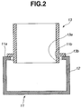
- FIG. 2 is a cross section taken along the axis the second tubular body
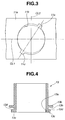
- FIG. 3 is a top view showing the first tubular body
- FIG. 4 is a side view showing the second tubular body
- FIG. 5 is a view similar to FIG. 2, showing the shape of the first tubular body before temporary fixing
- FIG. 6 is a view similar to FIG. 3, showing protrusions of the second tubular body inserted in recesses of a mounting surface of the first tubular body;
- FIG. 7 is a view similar to FIG. 6, showing the second tubular body turned from the state of FIG. 6.
- FIG. 8 is a view similar to FIG. 7, showing the relationship between the protrusions of the second tubular body and the edge of a mounting hole;
- FIG. 9 is a view similar to FIG. 5, showing a second embodiment of the present invention.
- FIG. 10 is a view similar to FIG. 8, showing the first tubular body of FIG. 9;
- FIG. 11 is a view similar to FIG. 10, showing a third embodiment of the present invention.
- FIG. 12 is a schematic drawing showing the details of the second tubular body of FIG. 11;
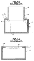
- FIG. 13 is a view similar to FIG. 9, showing a temporary fixing structure for tubular bodies in the related art.
- FIG. 14 is a view similar to FIG. 13, showing the bent state of the mounting surface of the first tubular body of FIG. 13.
- FIGS. 13-14 Before entering an explanation on a temporary fixing structure for tubular bodies embodying the present invention, the typical temporary fixing structure will be described in a little more detail.
- a tank main body 1 with a rectangular section serves as a mounting surface 1a to which a pipe 2 is fixed.
- the mounting surface 1a is formed with a mounting hole 1b.
- a flange 2a is formed with the pipe 2, and has an end portion 2b located ahead of the flange 2a and inserted in the mounting hole 1b of the mounting surface 1a of the tank main body 1.
- the pipe 2 is temporarily fixed to the tank main body 1 by calking a protrusion 2c formed at the head of the end portion 2b of the pipe 2.
- calking requires a special jig and enormous man-hours.
- the mounting surface 1a when forming the mounting hole 1b in the flat mounting surface 1a of the tank main body 1, the mounting surface 1a is bent inward with the mounting hole 1b as center, wherein a center bend dimension H is, for example, in the order of 0.1-0.3 mm.
- a center bend dimension H is, for example, in the order of 0.1-0.3 mm.
- FIGS. 1-12 a temporary fixing structure for tubular bodies embodying the present invention will be explained in detail.
- FIGS. 1-2 there is shown a first embodiment of a temporary fixing structure for tubular bodies according to the present invention.
- a first tubular body 11 as a tank main body of a heat exchanger such as radiator is a second tubular body 13 as a pipe for supplying or discharging cooling water or coolant.
- the first tubular body 11 which is made of aluminum, has a rectangular cross section, and is clad with a brazing material 12 on its outer surface and a sacrifice corrosion material on its inner surface.
- the thickness of the brazing material 12 as clad is 0.15 mm or less.
- a mounting hole 11b is formed in a mounting surface 11a of the first tubular body 11, in which an end portion 13a of the second tubular body 13 is inserted.
- the mounting hole 11b is formed like an ellipse so that the diameter in the direction of a centerline CL1 of the first tubular body 11 extending along the axial direction thereof is smaller than that in the direction of a centerline CL2 intersecting the axial direction at right angles.
- each recess 11c is formed at the mounting hole 11b on both sides of the centerline CL1 to face each other.
- each recess 11c is rectangular, and forms at an angle of 60° with respect to the centerline CL1.
- the second tubular body 13 which is made of aluminum, has a round cross section, and is clad with a sacrifice corrosion material on its inner surface.
- a flange 13b is integrally formed with the second tubular body 13.
- the flange 13b protrudes annularly along the outer periphery of the second tubular body 13.
- a flat portion 13h to be brazed to the mounting surface 11a is annularly formed with the flange 13b on side of the mounting surface 11a.
- the head of the end portion 13a of the second tubular body 13 located ahead of the flange 13b is inserted in the mounting hole 11b of the first tubular body 11.
- Protrusions 13c which can pass through the recesses 11c, are formed at the head of the end portion 13a of the second tubular body 13. Each protrusion 13c is so formed that the spacing between the protrusion 13c and the flange 13b is substantially equal to the thickness of the mounting surface 11a of the first tubular body 11.
- the side of the protrusion 13c of the second tubular body 13 facing the flange 13b includes an inclined face 13d inclined outward.
- the second tubular body 13 is temporarily fixed to the first tubular body 11 as described below. Referring to FIG. 5, in this embodiment, before temporary fixing of the second tubular body 13 to the first tubular body 11, the mounting surface 11a of the first tubular body 11 is bent inward for the reason of machining, etc.
- the protrusions 13c of the second tubular body 13 are inserted into the recesses 11c of the first tubular body 11. Then, the second tubular body 13 is turned in the direction of arrow in FIG. 6 to align the protrusions 13c with the centerline CL1 as shown in FIG. 7.
- This state involves the temporarily fixed state shown in FIGS. 1-2, wherein the flange 13b of the second tubular body 13 abuts on the mounting surface 11a of the first tubular body 11, obtaining firm temporary fixing of the second tubular body 13 to the first tubular body 11.
- the side of the protrusion 13c of the second tubular body 13 facing the flange 13b includes inclined face 13d inclined outward, and the mounting hole 11b of the first tubular body 11 is formed like an ellipse with smaller diameter or minor axis in the direction of the centerline CL1.
- the edge of the mounting hole 11 b is positioned on the inward side of the inclined face 13d as the protrusions 13c approach the centerline CL1.
- a portion of the first tubular body 11 corresponding to the edge of the mounting hole 11b is firmly held between the inclined face 13d and flange 13b through the cam action of the inclined face 13d.
- the protrusions 13c of the second tubular body 13 are inserted into the recesses 11c of the first tubular body 11, and then the second tubular body 13 is turned to align the protrusions 13c with the centerline CL1, leading to the flange 13b of the second tubular body 13 abutting on the mounting surface 11a of the first tubular body 11. This allows easy and secure temporary fixing of the flanges 13b of the second tubular body 13 to the flat mounting surface 11a of the first tubular body 11 in the close contact state.
- the side of the protrusion 13c of the second tubular body 13 facing the flange 13b includes inclined surface 13d inclined outward, so that even if any machining error occurs in the spacing between the flange 13b of the second tubular body 13 and the protrusion 13c, the flange 13b of the second tubular body 13 can securely abut on the mounting surface 11 a of the first tubular body 11.
- the side of the protrusion 13c of the second tubular body 13 facing the flange 13b includes inclined surface 13d inclined outward, and the mounting hole 11b of the first tubular body 11 is formed like an ellipse with smaller diameter or minor axis in the direction of the centerline CL1, allowing firmer temporary fixing of the flange 13b of the second tubular body 13 to the flat mounting surface 11a of the first tubular body 11.
- the thickness of the brazing material 12 is 0.15 mm or less, so that the brazing material 12, even if melted during brazing, can be maintained between the mounting surface 11a of the first tubular body 11 and the flange 13b of the second tubular body 13 which are in close in contact with each other, allowing firm brazing.
- FIGS. 9-10 there is shown a second embodiment of a temporary fixing structure for tubular bodies according to the present invention, wherein before temporary fixing of the second tubular body 13 to the first tubular body 11, the first tubular body 11 is slightly deformed inward at the edges of the mounting hole 11b along the centerline CL1 to form a depression 11e.
- the depression 11e is formed, for example, during press working of the mounting hole 11b into the mounting surface 11a.
- a positioning protrusion 11h is formed with the first tubular body 11 at one edge of the mounting hole 11b and on one side with respect to the centerline CL1.
- the positioning protrusion 11h serves to position the second tubular body 13 by abutting on the side of the protrusion 13c of the second tubular body 13.
- the protrusions 13c bring the mounting surface 11a and the flange 13b into close contact through the cam action of the depression 11e at the edges of the first tubular body 11 at the mounting hole 11b and along the centerline CL1, achieving firm temporary fixing of the second tubular body 13 to the first tubular body 11. This allows firmer temporary fixing of the second tubular body 13 by the first tubular body 11.
- the positioning protrusion 11h is formed at the edge of the mounting hole 11b of the first tubular body 11, allowing easy and secure positioning of the second tubular body 13.
- the protrusion 13c may be formed without inclined surface 13d.
- FIG. 11 there is shown a third embodiment of a temporary fixing structure for tubular bodies according to the present invention, wherein the outer periphery between the flange 13b and the protrusions 13c of the second tubular body 13 is formed like an ellipse so that a diameter R1 corresponding to the protrusions 13c is the largest.
- the other structures are the same as those in the first embodiment, and therefore, a detailed explanation thereof is omitted.
- the outer periphery between the flange 13b and the protrusions 13c of the second tubular body 13 is formed like an ellipse so that a diameter R1 corresponding to the protrusions 13c is the largest, causing no interference of the second tubular body 13 with the mounting hole 11b, allowing easy turning of the second tubular body 13.
- maintaining of the dimensional accuracy of the smaller diameter of the mounting hole 11b of the first tubular body 11 along the centerline CL1 and the largest diameter R1 of the outer periphery of the second tubular body 13 corresponding to the protrusions 13c allows firm temporary fixing of the first and second tubular bodies 11, 13, facilitating machining thereof.
- the second tubular body 13A is obtained out of a pipe member, and includes a flat portion 13h on the side of the protrusion 13c of the flange 13b.
- the second tubular body 13A includes on the side opposite to the protrusions 13c an annular protrusion 13i and small protrusions 13j for preventing hose coming-off.
- the other structures are the same as those in the first embodiment, and therefore, a detailed explanation thereof is omitted.
- the present invention is applied to first and second tubular bodies 11, 13 of a heat exchanger.
- the present invention can widely be applied to temporary fixing of two tubular bodies of various devices.
- the mounting hole 11b of the mounting surface 11a of the first tubular body 11 is formed like an ellipse.
- the mounting hole 11b may be formed circularly when having the mounting surface 11a bent or the depression 11e formed.
Abstract
Description
- The present invention relates to a temporary fixing structure for tubular bodies.
- In recent years, tanks for heat exchangers such as radiator and condenser are made of aluminum. Such tanks comprise an aluminum tank main body and an aluminum pipe brazed thereto for serving as a cooling water or coolant supplying or discharging tube.
- Brazing of the pipe to the tank main body is carried out such that after temporarily fixing the pipe to the tank main body, the assembly is coated with a noncorrosive flux, and then subjected to heat treatment in a brazing furnace.
- As will be described in detail later, a typical temporary fixing structure for the pipe to the tank main body is carried out by calking a protrusion formed at the head of an end portion of the pipe.
- However, the typical temporary fixing structure presents a problem of requiring a special jig and enormous man-hours for calking the protrusion formed at the head of an end portion of the pipe.
- Moreover, when forming a mounting hole in a flat mounting surface of the tank main body through, e.g. punch working, the mounting surface is bent inward with the mounting hole as center. Thus, after temporary fixing of the pipe to the tank main body, a clearance is formed between a flange of the pipe and the mounting surface of the tank main body, which may make sure brazing of the flange to the mounting surface difficult.
- It is, therefore, an object of the present invention to provide a temporary fixing structure for tubular bodies, which allows easy and secure temporary fixing of tubular bodies with no special jig and less man-hours.
- The present invention provides generally a structure which comprises: a first tubular body, the first tubular body having a surface with a hole; a second tubular body, the second tubular body having an end portion inserted in the hole of the first tubular body; a flange arranged at the end portion of the second tubular body, the flange including a flat portion abutting on the surface of the first tubular body; recesses formed with the hole of the first tubular body, the recesses facing each other, wherein a diameter of the hole extending along the recesses is smaller than that of the flange; and protrusions arranged at a head of the end portion of the second tubular body, wherein a spacing between each protrusion and the flange is substantially equal to a thickness of the surface of the first tubular body, wherein the protrusions are arranged inside the fist tubular body through the recesses, wherein the second tubular body is tumed with respect to the first tubular body to bring the flat portion of the flange into close contact with the surface of the first tubular body.
- A main feature of the present invention is to provide a structure which comprises: a first tubular body, the first tubular body having a surface with a hole; a second tubular body, the second tubular body having an end portion inserted in the hole of the first tubular body; a flange arranged at the end portion of the second tubular body, the flange including a flat portion abutting on the surface of the first tubular body; a brazing material placed on at least one of the flat portion of the flange and a portion of the face of the first tubular body corresponding to the flat portion; recesses formed with the hole of the first tubular body, the recesses facing each other, wherein a diameter of the hole extending along the recesses is smaller than that of the flange; and protrusions arranged at a head of the end portion of the second tubular body, wherein a spacing between each protrusion and the flange is substantially equal to a thickness of the surface of the first tubular body, wherein the protrusions are arranged inside the fist tubular body through the recesses, wherein the second tubular body is turned with respect to the first tubular body to bring the flat portion of the flange into close contact with the surface of the first tubular body.
- The other objects and features of the present invention will become apparent from the following description with reference to the accompanying drawings, wherein:
- FIG. 1 is a longitudinal section showing a first embodiment of a temporary fixing structure for tubular bodies according to the present invention;
- FIG. 2 is a cross section taken along the axis the second tubular body;
- FIG. 3 is a top view showing the first tubular body;
- FIG. 4 is a side view showing the second tubular body;
- FIG. 5 is a view similar to FIG. 2, showing the shape of the first tubular body before temporary fixing;
- FIG. 6 is a view similar to FIG. 3, showing protrusions of the second tubular body inserted in recesses of a mounting surface of the first tubular body;
- FIG. 7 is a view similar to FIG. 6, showing the second tubular body turned from the state of FIG. 6.
- FIG. 8 is a view similar to FIG. 7, showing the relationship between the protrusions of the second tubular body and the edge of a mounting hole;
- FIG. 9 is a view similar to FIG. 5, showing a second embodiment of the present invention;
- FIG. 10 is a view similar to FIG. 8, showing the first tubular body of FIG. 9;
- FIG. 11 is a view similar to FIG. 10, showing a third embodiment of the present invention;
- FIG. 12 is a schematic drawing showing the details of the second tubular body of FIG. 11;
- FIG. 13 is a view similar to FIG. 9, showing a temporary fixing structure for tubular bodies in the related art; and
- FIG. 14 is a view similar to FIG. 13, showing the bent state of the mounting surface of the first tubular body of FIG. 13.
- Referring to FIGS. 13-14, before entering an explanation on a temporary fixing structure for tubular bodies embodying the present invention, the typical temporary fixing structure will be described in a little more detail. Referring to FIG. 13, one side of a tank
main body 1 with a rectangular section serves as amounting surface 1a to which apipe 2 is fixed. Themounting surface 1a is formed with amounting hole 1b. Aflange 2a is formed with thepipe 2, and has anend portion 2b located ahead of theflange 2a and inserted in themounting hole 1b of themounting surface 1a of the tankmain body 1. - As described hereinbefore, the
pipe 2 is temporarily fixed to the tankmain body 1 by calking aprotrusion 2c formed at the head of theend portion 2b of thepipe 2. Such calking requires a special jig and enormous man-hours. - Moreover, referring to FIG. 14, when forming the
mounting hole 1b in theflat mounting surface 1a of the tankmain body 1, themounting surface 1a is bent inward with themounting hole 1b as center, wherein a center bend dimension H is, for example, in the order of 0.1-0.3 mm. Thus, after temporary fixing, a clearance is formed between theflange 2a of thepipe 2 and themounting surface 1a of the tankmain body 1, which may make sure brazing of theflange 2a to themounting surface 1a difficult. - Referring now to FIGS. 1-12, a temporary fixing structure for tubular bodies embodying the present invention will be explained in detail.
- Referring to FIGS. 1-2, there is shown a first embodiment of a temporary fixing structure for tubular bodies according to the present invention. In this embodiment, temporarily fixed to a first
tubular body 11 as a tank main body of a heat exchanger such as radiator is a secondtubular body 13 as a pipe for supplying or discharging cooling water or coolant. - The first
tubular body 11, which is made of aluminum, has a rectangular cross section, and is clad with abrazing material 12 on its outer surface and a sacrifice corrosion material on its inner surface. The thickness of thebrazing material 12 as clad is 0.15 mm or less. - A
mounting hole 11b is formed in amounting surface 11a of the firsttubular body 11, in which anend portion 13a of the secondtubular body 13 is inserted. Referring to FIG. 3, themounting hole 11b is formed like an ellipse so that the diameter in the direction of a centerline CL1 of the firsttubular body 11 extending along the axial direction thereof is smaller than that in the direction of a centerline CL2 intersecting the axial direction at right angles. -
Recesses 11 c are formed at themounting hole 11b on both sides of the centerline CL1 to face each other. In this embodiment, eachrecess 11c is rectangular, and forms at an angle of 60° with respect to the centerline CL1. - On the other hand, the second
tubular body 13, which is made of aluminum, has a round cross section, and is clad with a sacrifice corrosion material on its inner surface. - A
flange 13b is integrally formed with the secondtubular body 13. Theflange 13b protrudes annularly along the outer periphery of the secondtubular body 13. Aflat portion 13h to be brazed to themounting surface 11a is annularly formed with theflange 13b on side of themounting surface 11a. The head of theend portion 13a of the secondtubular body 13 located ahead of theflange 13b is inserted in themounting hole 11b of the firsttubular body 11. -
Protrusions 13c, which can pass through therecesses 11c, are formed at the head of theend portion 13a of the secondtubular body 13. Eachprotrusion 13c is so formed that the spacing between theprotrusion 13c and theflange 13b is substantially equal to the thickness of themounting surface 11a of the firsttubular body 11. - Referring to FIG. 4, in this embodiment, the side of the
protrusion 13c of the secondtubular body 13 facing theflange 13b includes aninclined face 13d inclined outward. - In this embodiment, the second
tubular body 13 is temporarily fixed to the firsttubular body 11 as described below. Referring to FIG. 5, in this embodiment, before temporary fixing of the secondtubular body 13 to the firsttubular body 11, themounting surface 11a of the firsttubular body 11 is bent inward for the reason of machining, etc. - Referring to FIG. 6, first, the
protrusions 13c of the secondtubular body 13 are inserted into therecesses 11c of the firsttubular body 11. Then, the secondtubular body 13 is turned in the direction of arrow in FIG. 6 to align theprotrusions 13c with the centerline CL1 as shown in FIG. 7. This state involves the temporarily fixed state shown in FIGS. 1-2, wherein theflange 13b of the secondtubular body 13 abuts on themounting surface 11a of the firsttubular body 11, obtaining firm temporary fixing of the secondtubular body 13 to the firsttubular body 11. - In the first embodiment, since the
mounting surface 11a of the firsttubular body 11 is bent inward for the reason of machining, etc. as shown in FIG. 5, two edges of the firsttubular body 11 at themounting hole 11b and along the centerline CL1 are deformed outward by theprotrusions 13c of the secondtubular body 13, which leads to not only correction of a bend of themounting surface 11a, but firm temporary fixing of the secondtubular body 13 to the firsttubular body 11. - Moreover, in the first embodiment, the side of the
protrusion 13c of the secondtubular body 13 facing theflange 13b includesinclined face 13d inclined outward, and themounting hole 11b of the firsttubular body 11 is formed like an ellipse with smaller diameter or minor axis in the direction of the centerline CL1. Thus, referring to FIG. 8, when the secondtubular body 13 is turned in the direction of arrows after inserting theprotrusions 13c of the secondtubular body 13 into therecesses 13c, the edge of themounting hole 11 b is positioned on the inward side of theinclined face 13d as theprotrusions 13c approach the centerline CL1. And therefore, a portion of the firsttubular body 11 corresponding to the edge of themounting hole 11b is firmly held between theinclined face 13d andflange 13b through the cam action of theinclined face 13d. - Further, in the first embodiment, the
protrusions 13c of the secondtubular body 13 are inserted into therecesses 11c of the firsttubular body 11, and then the secondtubular body 13 is turned to align theprotrusions 13c with the centerline CL1, leading to theflange 13b of the secondtubular body 13 abutting on themounting surface 11a of the firsttubular body 11. This allows easy and secure temporary fixing of theflanges 13b of the secondtubular body 13 to theflat mounting surface 11a of the firsttubular body 11 in the close contact state. - Therefore, no clearance is formed between the
flange 13b of the secondtubular body 13 and the mountingsurface 11a of the firsttubular body 11 after temporary fixing of the secondtubular body 13 to the firsttubular body 11, allowing secure brazing of theflange 13b to the mountingsurface 11a. Especially, when the mountingsurface 11a of the firsttubular body 11 is bent inward in the direction intersecting the axial direction at right angles for the reason of machining, etc., the edges of the firsttubular body 11 at the mountinghole 11b and along the centerline CL1 are deformed outward by theprotrusions 13c of thesecond tubular 13, allowing firm temporary fixing of the secondtubular body 13 to the firsttubular body 11 while correcting a bend of the mountingsurface 11a. - Furthermore, in the first embodiment, the side of the
protrusion 13c of the secondtubular body 13 facing theflange 13b includesinclined surface 13d inclined outward, so that even if any machining error occurs in the spacing between theflange 13b of the secondtubular body 13 and theprotrusion 13c, theflange 13b of the secondtubular body 13 can securely abut on the mountingsurface 11 a of the firsttubular body 11. - Still further, in the first embodiment, the side of the
protrusion 13c of the secondtubular body 13 facing theflange 13b includesinclined surface 13d inclined outward, and the mountinghole 11b of the firsttubular body 11 is formed like an ellipse with smaller diameter or minor axis in the direction of the centerline CL1, allowing firmer temporary fixing of theflange 13b of the secondtubular body 13 to theflat mounting surface 11a of the firsttubular body 11. - Furthermore, in the first embodiment, the thickness of the
brazing material 12 is 0.15 mm or less, so that thebrazing material 12, even if melted during brazing, can be maintained between the mountingsurface 11a of the firsttubular body 11 and theflange 13b of the secondtubular body 13 which are in close in contact with each other, allowing firm brazing. - Referring to FIGS. 9-10, there is shown a second embodiment of a temporary fixing structure for tubular bodies according to the present invention, wherein before temporary fixing of the second
tubular body 13 to the firsttubular body 11, the firsttubular body 11 is slightly deformed inward at the edges of the mountinghole 11b along the centerline CL1 to form adepression 11e. Thedepression 11e is formed, for example, during press working of the mountinghole 11b into the mountingsurface 11a. - A
positioning protrusion 11h is formed with the firsttubular body 11 at one edge of the mountinghole 11b and on one side with respect to the centerline CL1. Thepositioning protrusion 11h serves to position the secondtubular body 13 by abutting on the side of theprotrusion 13c of the secondtubular body 13. The other structures are the same as those in the first embodiment, and therefore, a detailed explanation thereof is omitted. - In the second embodiment, when the second
tubular body 13 is turned after inserting theprotrusions 13c of the secondtubular body 13 into therecesses 11c of the firsttubular body 11, theprotrusions 13c bring the mountingsurface 11a and theflange 13b into close contact through the cam action of thedepression 11e at the edges of the firsttubular body 11 at the mountinghole 11b and along the centerline CL1, achieving firm temporary fixing of the secondtubular body 13 to the firsttubular body 11. This allows firmer temporary fixing of the secondtubular body 13 by the firsttubular body 11. - Moreover, in the second embodiment, the
positioning protrusion 11h is formed at the edge of the mountinghole 11b of the firsttubular body 11, allowing easy and secure positioning of the secondtubular body 13. - It is noted that, in the second embodiment, due to provision of the
depression 11e, theprotrusion 13c may be formed withoutinclined surface 13d. - Referring to FIG. 11, there is shown a third embodiment of a temporary fixing structure for tubular bodies according to the present invention, wherein the outer periphery between the
flange 13b and theprotrusions 13c of the secondtubular body 13 is formed like an ellipse so that a diameter R1 corresponding to theprotrusions 13c is the largest. The other structures are the same as those in the first embodiment, and therefore, a detailed explanation thereof is omitted. - In the third embodiment, the outer periphery between the
flange 13b and theprotrusions 13c of the secondtubular body 13 is formed like an ellipse so that a diameter R1 corresponding to theprotrusions 13c is the largest, causing no interference of the secondtubular body 13 with the mountinghole 11b, allowing easy turning of the secondtubular body 13. - Moreover, in the third embodiment, maintaining of the dimensional accuracy of the smaller diameter of the mounting
hole 11b of the firsttubular body 11 along the centerline CL1 and the largest diameter R1 of the outer periphery of the secondtubular body 13 corresponding to theprotrusions 13c allows firm temporary fixing of the first and secondtubular bodies - Referring to FIG. 12, there is shown an example of the specific shape of the second tubular body. In this example, the second
tubular body 13A is obtained out of a pipe member, and includes aflat portion 13h on the side of theprotrusion 13c of theflange 13b. The secondtubular body 13A includes on the side opposite to theprotrusions 13c anannular protrusion 13i andsmall protrusions 13j for preventing hose coming-off. The other structures are the same as those in the first embodiment, and therefore, a detailed explanation thereof is omitted. - Having described the present invention with regard to the preferred embodiments, it is noted that the present invention is not limited thereto, and various changes and modifications can be made without departing from the scope of the present invention.
- By way of example, in the illustrative embodiments, the present invention is applied to first and second
tubular bodies - Moreover, in the illustrative embodiments, the mounting
hole 11b of the mountingsurface 11a of the firsttubular body 11 is formed like an ellipse. Optionally, the mountinghole 11b may be formed circularly when having the mountingsurface 11a bent or thedepression 11e formed. - The entire teachings of Japanese Patent Application P2001-87646 filed March 26, 2001 are incorporated hereby by reference.
Claims (10)
- A structure, comprising:wherein the second tubular body is turned with respect to the first tubular body to bring the flat portion of the flange into close contact with the surface of the first tubular body.a first tubular body, the first tubular body having a surface with a hole;a second tubular body, the second tubular body having an end portion inserted in the hole of the first tubular body;a flange arranged at the end portion of the second tubular body, the flange including a flat portion abutting on the surface of the first tubular body;recesses formed with the hole of the first tubular body, the recesses facing each other, wherein a diameter of the hole extending along the recesses is smaller than that of the flange; andprotrusions arranged at a head of the end portion of the second tubular body, wherein a spacing between each protrusion and the flange is substantially equal to a thickness of the surface of the first tubular body, wherein the protrusions are arranged inside the fist tubular body through the recesses,
- The structure as claimed in claim 1, wherein the recesses are arranged on a line inclined with respect to a longitudinal direction of the first tubular body.
- The structure as claimed in claim 1, wherein each of the protrusions includes a face opposite to the flange, the face including an inclined face inclined outward to increase the spacing.
- The structure as claimed in claim 1, wherein the hole of the first tubular body is formed like an ellipse with a minor axis in a longitudinal direction of the first tubular body.
- The structure as claimed in claim 1, wherein the first tubular body is deformed inward at edges of the hole in a longitudinal direction of the first tubular body.
- The structure as claimed in claim 5, further comprising a positioning protrusion formed with the first tubular body at one edge of the hole and on one side with respect to the longitudinal direction.
- The structure as claimed in claim 4, wherein the ellipse has the largest diameter in a direction corresponding to the protrusions.
- The structure as claimed in claim 1, further comprising a brazing material placed on at least one of the flat portion of the flange and a portion of the face of the first tubular body corresponding to the flat portion.
- A structure, comprising:wherein the second tubular body is turned with respect to the first tubular body to bring the flat portion of the flange into close contact with the surface of the first tubular body.a first tubular body, the first tubular body having a surface with a hole;a second tubular body, the second tubular body having an end portion inserted in the hole of the first tubular body;a flange arranged at the end portion of the second tubular body, the flange including a flat portion abutting on the surface of the first tubular body;a brazing material placed on at least one of the flat portion of the flange and a portion of the face of the first tubular body corresponding to the flat portion;recesses formed with the hole of the first tubular body, the recesses facing each other, wherein a diameter of the hole extending along the recesses is smaller than that of the flange; andprotrusions arranged at a head of the end portion of the second tubular body, wherein a spacing between each protrusion and the flange is substantially equal to a thickness of the surface of the first tubular body, wherein the protrusions are arranged inside the fist tubular body through the recesses,
- A structure, comprising:wherein the second tubular body is turned with respect to the first tubular body to bring the flat portion of the flange into close contact with the surface of the first tubular body.a first tubular body, the first tubular body having a surface with a hole;a second tubular body, the second tubular body having an end portion inserted in the hole of the first tubular body;a flange arranged at the end portion of the second tubular body, the flange including a flat portion abutting on the surface of the first tubular body;means for defining recesses, the recesses defining means being arranged at the hole of the first tubular body, the recesses facing each other, wherein a diameter of the hole extending along the recesses is smaller than that of the flange; andprotrusions arranged at a head of the end portion of the second tubular body, wherein a spacing between each protrusion and the flange is substantially equal to a thickness of the surface of the first tubular body, wherein the protrusions are arranged inside the fist tubular body through the recesses,
Priority Applications (1)
| Application Number | Priority Date | Filing Date | Title |
|---|---|---|---|
| EP06018225A EP1754947A3 (en) | 2001-03-26 | 2002-03-19 | Temporary fixing structure for tubular bodies |
Applications Claiming Priority (2)
| Application Number | Priority Date | Filing Date | Title |
|---|---|---|---|
| JP2001087646A JP4689065B2 (en) | 2001-03-26 | 2001-03-26 | Temporary fixing structure of tube |
| JP2001087646 | 2001-03-26 |
Related Child Applications (1)
| Application Number | Title | Priority Date | Filing Date |
|---|---|---|---|
| EP06018225A Division EP1754947A3 (en) | 2001-03-26 | 2002-03-19 | Temporary fixing structure for tubular bodies |
Publications (3)
| Publication Number | Publication Date |
|---|---|
| EP1248065A2 true EP1248065A2 (en) | 2002-10-09 |
| EP1248065A3 EP1248065A3 (en) | 2003-03-19 |
| EP1248065B1 EP1248065B1 (en) | 2007-02-14 |
Family
ID=18942870
Family Applications (2)
| Application Number | Title | Priority Date | Filing Date |
|---|---|---|---|
| EP02006206A Expired - Lifetime EP1248065B1 (en) | 2001-03-26 | 2002-03-19 | Temporary fixing structure for tubular bodies |
| EP06018225A Withdrawn EP1754947A3 (en) | 2001-03-26 | 2002-03-19 | Temporary fixing structure for tubular bodies |
Family Applications After (1)
| Application Number | Title | Priority Date | Filing Date |
|---|---|---|---|
| EP06018225A Withdrawn EP1754947A3 (en) | 2001-03-26 | 2002-03-19 | Temporary fixing structure for tubular bodies |
Country Status (4)
| Country | Link |
|---|---|
| US (1) | US6708730B2 (en) |
| EP (2) | EP1248065B1 (en) |
| JP (1) | JP4689065B2 (en) |
| DE (1) | DE60218076T2 (en) |
Cited By (8)
| Publication number | Priority date | Publication date | Assignee | Title |
|---|---|---|---|---|
| EP1890103A1 (en) * | 2006-08-08 | 2008-02-20 | Delphi Technologies, Inc. | Pipe connecting structure for a heat exchanger |
| GB2469119A (en) * | 2009-04-03 | 2010-10-06 | Managed Pressure Operations Ll | Drill pipe connector |
| US8210266B2 (en) | 2008-10-22 | 2012-07-03 | Managed Pressure Operations Pte Ltd. | Drill pipe |
| US8360170B2 (en) | 2009-09-15 | 2013-01-29 | Managed Pressure Operations Pte Ltd. | Method of drilling a subterranean borehole |
| US8684109B2 (en) | 2010-11-16 | 2014-04-01 | Managed Pressure Operations Pte Ltd | Drilling method for drilling a subterranean borehole |
| US9051803B2 (en) | 2009-04-01 | 2015-06-09 | Managed Pressure Operations Pte Ltd | Apparatus for and method of drilling a subterranean borehole |
| WO2016128322A1 (en) * | 2015-02-09 | 2016-08-18 | Titanx Engine Cooling Holding Ab | Port flange for a heat exchanger and method of making a port flange |
| US9458696B2 (en) | 2010-12-24 | 2016-10-04 | Managed Pressure Operations Pte. Ltd. | Valve assembly |
Families Citing this family (17)
| Publication number | Priority date | Publication date | Assignee | Title |
|---|---|---|---|---|
| US6942255B2 (en) * | 2002-04-23 | 2005-09-13 | Q3Jmc, Inc. | Twist fitting for air tank connections |
| JP2005172270A (en) * | 2003-12-08 | 2005-06-30 | Calsonic Kansei Corp | Radiator incorporated with oil cooler |
| DE102004041303A1 (en) * | 2004-08-25 | 2006-03-02 | Behr Gmbh & Co. Kg | Container for heat exchanger, has hollow-cylindrical connectors soldered to circular openings formed on container, such that each connector can be adjustably positioned, rotated and held in each circular opening |
| EP1826175A4 (en) | 2004-10-27 | 2010-12-01 | Kyocera Corp | Container for housing fuel reformer and fuel reforming apparatus |
| JP5046484B2 (en) * | 2004-12-22 | 2012-10-10 | 京セラ株式会社 | Fuel reformer storage container and fuel reformer |
| US7380327B2 (en) * | 2005-01-20 | 2008-06-03 | Calsonickansei North America, Inc. | Tube interface and method of securing a first tube to a second tube |
| JP5107834B2 (en) * | 2008-09-01 | 2012-12-26 | 株式会社オノックスエムティーティー | Pipe structure |
| CN101791655B (en) * | 2010-03-11 | 2011-10-05 | 努奥罗(中国)有限公司 | Pipe fitting riveting machine |
| US9102445B2 (en) * | 2011-04-27 | 2015-08-11 | Caterpillar Inc. | Tank assembly having twist-and-lock mounting flange |
| US9951998B2 (en) * | 2013-09-30 | 2018-04-24 | Dana Canada Corporation | Heat exchanger with integrated co-axial inlet/outlet tube |
| US9827514B2 (en) * | 2015-02-24 | 2017-11-28 | Yamit Filtration & Water Treatment Ltd. | Fluid flow accessory |
| CA3026249A1 (en) * | 2016-06-02 | 2017-12-07 | Priefert Mfg. Co. Inc. | Apparatus, systems and methods for a brazed joint |
| US11079181B2 (en) * | 2018-05-03 | 2021-08-03 | Raytheon Technologies Corporation | Cast plate heat exchanger with tapered walls |
| DE102018114918A1 (en) * | 2018-06-21 | 2019-12-24 | Norma Germany Gmbh | Connection arrangement for forming a fluid-carrying connection |
| GB2575106B (en) | 2018-06-29 | 2020-09-02 | Airbus Operations Ltd | A duct stringer |
| EP3757501B1 (en) * | 2019-06-26 | 2023-03-15 | Valeo Autosystemy SP. Z.O.O. | A tank assembly for a heat exchanger |
| KR20210013827A (en) * | 2019-07-29 | 2021-02-08 | 엘지전자 주식회사 | Plate type heat exchanger |
Citations (10)
| Publication number | Priority date | Publication date | Assignee | Title |
|---|---|---|---|---|
| GB928633A (en) * | 1960-12-23 | 1963-06-12 | Bendix Corp | Connections for tubular members |
| US4133560A (en) * | 1976-06-28 | 1979-01-09 | Toyota Jidosha Kogyo Kabushiki Kaisha | Plug and attaching hole thereof |
| GB2119046A (en) * | 1982-04-21 | 1983-11-09 | Hoover Plc | Hose connector for a floor care appliance |
| JPH03188315A (en) * | 1989-12-18 | 1991-08-16 | Oki Electric Ind Co Ltd | Mounting structure of magnetic azimuth sensor |
| DE4445091A1 (en) * | 1993-12-17 | 1995-06-22 | Nippon Denso Co | Tube connection device for heat exchanger |
| US5555929A (en) * | 1994-05-23 | 1996-09-17 | Nippondenso Co., Ltd | Heat exchanger |
| EP0745824A1 (en) * | 1995-05-30 | 1996-12-04 | Sanden Corporation | Heat exchanger and method for manufacturing the same |
| JPH10238992A (en) * | 1997-02-21 | 1998-09-11 | Calsonic Corp | Pipe mounting structure to heat exchanger tank |
| DE19805439A1 (en) * | 1998-02-11 | 1999-08-12 | Behr Gmbh & Co | Assembly for soldering sealed plate heat exchangers |
| EP1285212A1 (en) * | 2000-05-29 | 2003-02-26 | Valeo Thermique Moteur | Manifold block for brazed heat exchanger |
Family Cites Families (13)
| Publication number | Priority date | Publication date | Assignee | Title |
|---|---|---|---|---|
| US978504A (en) * | 1910-04-08 | 1910-12-13 | Stewarts & Lloyds Ltd | Jointing of pipes and the like. |
| US3232644A (en) * | 1963-09-05 | 1966-02-01 | Bendix Corp | Twist lock check valve |
| DE1630311C3 (en) * | 1967-07-01 | 1973-01-04 | Daimler-Benz Ag, 7000 Stuttgart | Fastening arrangement of the full load stop for the accelerator pedal of a motor vehicle on the bulkhead |
| AT343059B (en) * | 1974-07-15 | 1978-05-10 | Grohe Armaturen Friedrich | SWIVEL SPOUT ON SANITARY FITTINGS |
| US4026456A (en) * | 1976-01-15 | 1977-05-31 | Modine Manufacturing Company | Method of attaching a tube to a wall |
| US4379574A (en) * | 1980-12-22 | 1983-04-12 | Ex-Cell-O Corporation | Radiator assembly (bayonet lock) |
| US4449737A (en) * | 1982-04-21 | 1984-05-22 | The Hoover Company | Hose coupler locking arrangement |
| JPH0113845Y2 (en) * | 1985-06-03 | 1989-04-24 | ||
| JPH0188186U (en) * | 1987-11-30 | 1989-06-09 | ||
| FR2702807B1 (en) * | 1993-03-17 | 1995-04-28 | Peugeot | Device for fixing a cylindrical housing to a support plate. |
| JPH0942233A (en) * | 1995-08-01 | 1997-02-10 | Kansei Corp | Mounting structure of automobile part |
| JPH10252727A (en) * | 1997-03-17 | 1998-09-22 | Nippon Plast Co Ltd | Mounting structure of synthetic resin part |
| JP2000202523A (en) * | 1999-01-07 | 2000-07-25 | Sanden Corp | Structure and method for temporarily fixing pipe during brazing |
-
2001
- 2001-03-26 JP JP2001087646A patent/JP4689065B2/en not_active Expired - Fee Related
-
2002
- 2002-03-19 EP EP02006206A patent/EP1248065B1/en not_active Expired - Lifetime
- 2002-03-19 EP EP06018225A patent/EP1754947A3/en not_active Withdrawn
- 2002-03-19 DE DE60218076T patent/DE60218076T2/en not_active Expired - Lifetime
- 2002-03-21 US US10/101,595 patent/US6708730B2/en not_active Expired - Lifetime
Patent Citations (10)
| Publication number | Priority date | Publication date | Assignee | Title |
|---|---|---|---|---|
| GB928633A (en) * | 1960-12-23 | 1963-06-12 | Bendix Corp | Connections for tubular members |
| US4133560A (en) * | 1976-06-28 | 1979-01-09 | Toyota Jidosha Kogyo Kabushiki Kaisha | Plug and attaching hole thereof |
| GB2119046A (en) * | 1982-04-21 | 1983-11-09 | Hoover Plc | Hose connector for a floor care appliance |
| JPH03188315A (en) * | 1989-12-18 | 1991-08-16 | Oki Electric Ind Co Ltd | Mounting structure of magnetic azimuth sensor |
| DE4445091A1 (en) * | 1993-12-17 | 1995-06-22 | Nippon Denso Co | Tube connection device for heat exchanger |
| US5555929A (en) * | 1994-05-23 | 1996-09-17 | Nippondenso Co., Ltd | Heat exchanger |
| EP0745824A1 (en) * | 1995-05-30 | 1996-12-04 | Sanden Corporation | Heat exchanger and method for manufacturing the same |
| JPH10238992A (en) * | 1997-02-21 | 1998-09-11 | Calsonic Corp | Pipe mounting structure to heat exchanger tank |
| DE19805439A1 (en) * | 1998-02-11 | 1999-08-12 | Behr Gmbh & Co | Assembly for soldering sealed plate heat exchangers |
| EP1285212A1 (en) * | 2000-05-29 | 2003-02-26 | Valeo Thermique Moteur | Manifold block for brazed heat exchanger |
Non-Patent Citations (2)
| Title |
|---|
| PATENT ABSTRACTS OF JAPAN vol. 015, no. 449 (P-1275), 14 November 1991 (1991-11-14) -& JP 03 188315 A (OKI ELECTRIC IND CO LTD), 16 August 1991 (1991-08-16) * |
| PATENT ABSTRACTS OF JAPAN vol. 1998, no. 14, 31 December 1998 (1998-12-31) -& JP 10 238992 A (CALSONIC CORP), 11 September 1998 (1998-09-11) * |
Cited By (11)
| Publication number | Priority date | Publication date | Assignee | Title |
|---|---|---|---|---|
| EP1890103A1 (en) * | 2006-08-08 | 2008-02-20 | Delphi Technologies, Inc. | Pipe connecting structure for a heat exchanger |
| US8210266B2 (en) | 2008-10-22 | 2012-07-03 | Managed Pressure Operations Pte Ltd. | Drill pipe |
| US9051803B2 (en) | 2009-04-01 | 2015-06-09 | Managed Pressure Operations Pte Ltd | Apparatus for and method of drilling a subterranean borehole |
| GB2469119A (en) * | 2009-04-03 | 2010-10-06 | Managed Pressure Operations Ll | Drill pipe connector |
| GB2469119B (en) * | 2009-04-03 | 2013-07-03 | Managed Pressure Operations | Drill pipe connector |
| US9284800B2 (en) | 2009-04-03 | 2016-03-15 | Managed Pressure Operations Pte Ltd. | Drill pipe connector |
| US8360170B2 (en) | 2009-09-15 | 2013-01-29 | Managed Pressure Operations Pte Ltd. | Method of drilling a subterranean borehole |
| US8684109B2 (en) | 2010-11-16 | 2014-04-01 | Managed Pressure Operations Pte Ltd | Drilling method for drilling a subterranean borehole |
| US9506336B2 (en) | 2010-11-16 | 2016-11-29 | Managed Pressure Operations Pte Ltd | Method and apparatus for drilling subterranean borehole |
| US9458696B2 (en) | 2010-12-24 | 2016-10-04 | Managed Pressure Operations Pte. Ltd. | Valve assembly |
| WO2016128322A1 (en) * | 2015-02-09 | 2016-08-18 | Titanx Engine Cooling Holding Ab | Port flange for a heat exchanger and method of making a port flange |
Also Published As
| Publication number | Publication date |
|---|---|
| JP2002282934A (en) | 2002-10-02 |
| DE60218076T2 (en) | 2007-05-31 |
| JP4689065B2 (en) | 2011-05-25 |
| US6708730B2 (en) | 2004-03-23 |
| DE60218076D1 (en) | 2007-03-29 |
| EP1248065B1 (en) | 2007-02-14 |
| US20020134453A1 (en) | 2002-09-26 |
| EP1754947A2 (en) | 2007-02-21 |
| EP1754947A3 (en) | 2007-03-28 |
| EP1248065A3 (en) | 2003-03-19 |
Similar Documents
| Publication | Publication Date | Title |
|---|---|---|
| US6708730B2 (en) | Temporary fixing structure for tubular bodies | |
| US6474698B2 (en) | Connection piece for a heat exchanger | |
| US6269870B1 (en) | Exhaust heat exchanger | |
| US7429065B2 (en) | Hose and tube assembly | |
| JP2017075741A (en) | Heat exchanger | |
| US5937938A (en) | Oil cooler mounting structure and oil cooler mounting method | |
| JP4153178B2 (en) | Heat exchanger tank and manufacturing method thereof | |
| US20110277954A1 (en) | Manifold bending support and method for using same | |
| JP2000220988A (en) | Heat exchanger | |
| JP2006132653A (en) | Double pipe, its manufacturing method, and supporting member of double pipe | |
| JPS6211450B2 (en) | ||
| JP5060872B2 (en) | Radiator resin tank structure | |
| US5868196A (en) | Mounting bracket for heat exchanger | |
| US5758904A (en) | System and method for securing a block to a manifold for a heat exchanger | |
| US20170335993A1 (en) | Pipe fixing device | |
| JPH10246591A (en) | Heat-exchanger and manufacture thereof | |
| JPH0229435Y2 (en) | ||
| JP2007093035A (en) | Welding structure and welding method for aluminum accumulator, and heat exchanger | |
| JP2008261550A (en) | Heat exchanger and its manufacturing method | |
| JP2006234353A (en) | Welding structure and welding method of aluminum accumulator, and heat exchanger | |
| JPH0315896Y2 (en) | ||
| JP2006023018A (en) | Welding structure and welding method for aluminum accumulator, and heat exchanger | |
| CN218818650U (en) | Clamping structure and vehicle with same | |
| JP2008267693A (en) | Heat exchanger | |
| JP3479136B2 (en) | Pipe fittings |
Legal Events
| Date | Code | Title | Description |
|---|---|---|---|
| PUAI | Public reference made under article 153(3) epc to a published international application that has entered the european phase |
Free format text: ORIGINAL CODE: 0009012 |
|
| 17P | Request for examination filed |
Effective date: 20020319 |
|
| AK | Designated contracting states |
Kind code of ref document: A2 Designated state(s): AT BE CH CY DE DK ES FI FR GB GR IE IT LI LU MC NL PT SE TR |
|
| AX | Request for extension of the european patent |
Free format text: AL;LT;LV;MK;RO;SI |
|
| PUAL | Search report despatched |
Free format text: ORIGINAL CODE: 0009013 |
|
| AK | Designated contracting states |
Kind code of ref document: A3 Designated state(s): AT BE CH CY DE DK ES FI FR GB GR IE IT LI LU MC NL PT SE TR |
|
| AX | Request for extension of the european patent |
Extension state: AL LT LV MK RO SI |
|
| AKX | Designation fees paid |
Designated state(s): DE FR GB |
|
| 17Q | First examination report despatched |
Effective date: 20040416 |
|
| GRAP | Despatch of communication of intention to grant a patent |
Free format text: ORIGINAL CODE: EPIDOSNIGR1 |
|
| GRAS | Grant fee paid |
Free format text: ORIGINAL CODE: EPIDOSNIGR3 |
|
| GRAA | (expected) grant |
Free format text: ORIGINAL CODE: 0009210 |
|
| AK | Designated contracting states |
Kind code of ref document: B1 Designated state(s): DE FR GB |
|
| REG | Reference to a national code |
Ref country code: GB Ref legal event code: FG4D |
|
| REF | Corresponds to: |
Ref document number: 60218076 Country of ref document: DE Date of ref document: 20070329 Kind code of ref document: P |
|
| ET | Fr: translation filed | ||
| PLBE | No opposition filed within time limit |
Free format text: ORIGINAL CODE: 0009261 |
|
| STAA | Information on the status of an ep patent application or granted ep patent |
Free format text: STATUS: NO OPPOSITION FILED WITHIN TIME LIMIT |
|
| 26N | No opposition filed |
Effective date: 20071115 |
|
| REG | Reference to a national code |
Ref country code: GB Ref legal event code: 746 Effective date: 20090924 |
|
| REG | Reference to a national code |
Ref country code: FR Ref legal event code: PLFP Year of fee payment: 15 |
|
| PGFP | Annual fee paid to national office [announced via postgrant information from national office to epo] |
Ref country code: DE Payment date: 20160315 Year of fee payment: 15 |
|
| PGFP | Annual fee paid to national office [announced via postgrant information from national office to epo] |
Ref country code: FR Payment date: 20160208 Year of fee payment: 15 Ref country code: GB Payment date: 20160316 Year of fee payment: 15 |
|
| REG | Reference to a national code |
Ref country code: DE Ref legal event code: R119 Ref document number: 60218076 Country of ref document: DE |
|
| GBPC | Gb: european patent ceased through non-payment of renewal fee |
Effective date: 20170319 |
|
| REG | Reference to a national code |
Ref country code: FR Ref legal event code: ST Effective date: 20171130 |
|
| PG25 | Lapsed in a contracting state [announced via postgrant information from national office to epo] |
Ref country code: FR Free format text: LAPSE BECAUSE OF NON-PAYMENT OF DUE FEES Effective date: 20170331 Ref country code: DE Free format text: LAPSE BECAUSE OF NON-PAYMENT OF DUE FEES Effective date: 20171003 |
|
| PG25 | Lapsed in a contracting state [announced via postgrant information from national office to epo] |
Ref country code: GB Free format text: LAPSE BECAUSE OF NON-PAYMENT OF DUE FEES Effective date: 20170319 |