JP3880098B2 - Heat exchanger and header pipe manufacturing method - Google Patents
Heat exchanger and header pipe manufacturing method Download PDFInfo
- Publication number
- JP3880098B2 JP3880098B2 JP07252596A JP7252596A JP3880098B2 JP 3880098 B2 JP3880098 B2 JP 3880098B2 JP 07252596 A JP07252596 A JP 07252596A JP 7252596 A JP7252596 A JP 7252596A JP 3880098 B2 JP3880098 B2 JP 3880098B2
- Authority
- JP
- Japan
- Prior art keywords
- header
- tube
- heat exchanger
- insertion hole
- burring
- Prior art date
- Legal status (The legal status is an assumption and is not a legal conclusion. Google has not performed a legal analysis and makes no representation as to the accuracy of the status listed.)
- Expired - Fee Related
Links
- 238000004519 manufacturing process Methods 0.000 title description 7
- 238000003780 insertion Methods 0.000 claims description 58
- 230000037431 insertion Effects 0.000 claims description 58
- 238000005219 brazing Methods 0.000 claims description 29
- 239000000463 material Substances 0.000 claims description 19
- 230000002093 peripheral effect Effects 0.000 claims description 15
- 238000005452 bending Methods 0.000 claims description 14
- 229910052782 aluminium Inorganic materials 0.000 claims description 10
- XAGFODPZIPBFFR-UHFFFAOYSA-N aluminium Chemical compound [Al] XAGFODPZIPBFFR-UHFFFAOYSA-N 0.000 claims description 10
- 238000000034 method Methods 0.000 claims description 9
- 239000000945 filler Substances 0.000 claims description 8
- 230000008569 process Effects 0.000 claims description 8
- 230000001154 acute effect Effects 0.000 claims description 3
- 238000004891 communication Methods 0.000 claims description 2
- 230000009471 action Effects 0.000 description 5
- 239000003507 refrigerant Substances 0.000 description 5
- 230000007547 defect Effects 0.000 description 4
- 229910052751 metal Inorganic materials 0.000 description 3
- 239000002184 metal Substances 0.000 description 3
- 238000005192 partition Methods 0.000 description 3
- 230000001939 inductive effect Effects 0.000 description 2
- 230000036544 posture Effects 0.000 description 2
- 230000008859 change Effects 0.000 description 1
- 230000008602 contraction Effects 0.000 description 1
- 230000000694 effects Effects 0.000 description 1
- 238000009434 installation Methods 0.000 description 1
- 238000005304 joining Methods 0.000 description 1
- 230000009466 transformation Effects 0.000 description 1
- 230000007704 transition Effects 0.000 description 1
Images

Classifications
-
- F—MECHANICAL ENGINEERING; LIGHTING; HEATING; WEAPONS; BLASTING
- F28—HEAT EXCHANGE IN GENERAL
- F28F—DETAILS OF HEAT-EXCHANGE AND HEAT-TRANSFER APPARATUS, OF GENERAL APPLICATION
- F28F9/00—Casings; Header boxes; Auxiliary supports for elements; Auxiliary members within casings
- F28F9/02—Header boxes; End plates
- F28F9/04—Arrangements for sealing elements into header boxes or end plates
- F28F9/16—Arrangements for sealing elements into header boxes or end plates by permanent joints, e.g. by rolling
- F28F9/18—Arrangements for sealing elements into header boxes or end plates by permanent joints, e.g. by rolling by welding
- F28F9/182—Arrangements for sealing elements into header boxes or end plates by permanent joints, e.g. by rolling by welding the heat-exchange conduits having ends with a particular shape, e.g. deformed; the heat-exchange conduits or end plates having supplementary joining means, e.g. abutments
-
- F—MECHANICAL ENGINEERING; LIGHTING; HEATING; WEAPONS; BLASTING
- F28—HEAT EXCHANGE IN GENERAL
- F28D—HEAT-EXCHANGE APPARATUS, NOT PROVIDED FOR IN ANOTHER SUBCLASS, IN WHICH THE HEAT-EXCHANGE MEDIA DO NOT COME INTO DIRECT CONTACT
- F28D1/00—Heat-exchange apparatus having stationary conduit assemblies for one heat-exchange medium only, the media being in contact with different sides of the conduit wall, in which the other heat-exchange medium is a large body of fluid, e.g. domestic or motor car radiators
- F28D1/02—Heat-exchange apparatus having stationary conduit assemblies for one heat-exchange medium only, the media being in contact with different sides of the conduit wall, in which the other heat-exchange medium is a large body of fluid, e.g. domestic or motor car radiators with heat-exchange conduits immersed in the body of fluid
- F28D1/04—Heat-exchange apparatus having stationary conduit assemblies for one heat-exchange medium only, the media being in contact with different sides of the conduit wall, in which the other heat-exchange medium is a large body of fluid, e.g. domestic or motor car radiators with heat-exchange conduits immersed in the body of fluid with tubular conduits
- F28D1/053—Heat-exchange apparatus having stationary conduit assemblies for one heat-exchange medium only, the media being in contact with different sides of the conduit wall, in which the other heat-exchange medium is a large body of fluid, e.g. domestic or motor car radiators with heat-exchange conduits immersed in the body of fluid with tubular conduits the conduits being straight
- F28D1/0535—Heat-exchange apparatus having stationary conduit assemblies for one heat-exchange medium only, the media being in contact with different sides of the conduit wall, in which the other heat-exchange medium is a large body of fluid, e.g. domestic or motor car radiators with heat-exchange conduits immersed in the body of fluid with tubular conduits the conduits being straight the conduits having a non-circular cross-section
- F28D1/05366—Assemblies of conduits connected to common headers, e.g. core type radiators
- F28D1/05391—Assemblies of conduits connected to common headers, e.g. core type radiators with multiple rows of conduits or with multi-channel conduits combined with a particular flow pattern, e.g. multi-row multi-stage radiators
-
- F—MECHANICAL ENGINEERING; LIGHTING; HEATING; WEAPONS; BLASTING
- F28—HEAT EXCHANGE IN GENERAL
- F28F—DETAILS OF HEAT-EXCHANGE AND HEAT-TRANSFER APPARATUS, OF GENERAL APPLICATION
- F28F9/00—Casings; Header boxes; Auxiliary supports for elements; Auxiliary members within casings
- F28F9/02—Header boxes; End plates
Landscapes
- Engineering & Computer Science (AREA)
- Physics & Mathematics (AREA)
- Thermal Sciences (AREA)
- Mechanical Engineering (AREA)
- General Engineering & Computer Science (AREA)
- Details Of Heat-Exchange And Heat-Transfer (AREA)
Description
【0001】
【発明の属する技術分野】
この発明は、カーエアコン用凝縮器、ルームエアコン用室外熱交換器、パッケージ型エアコン用室外熱交換器、自動販売機用凝縮器、などに用いられうるアルミニウム等の金属製の熱交換器、及びこの熱交換器に用いられるヘッダーパイプの製造方法に関する。
【0002】
【従来の技術】
例えばカークーラー用凝縮器として、複数本の熱交換用チューブが所定間隔おきに並列状態に配置されると共に、これらチューブの両端部にそれぞれ中空ヘッダーが連通状態に接続され、かつ、チューブ間にコルゲートフィンが配置された構造の、いわゆるマルチフロータイプと称されている熱交換器が好んで使用される傾向にある。
【0003】
例えばこのタイプの熱交換器において、チューブとヘッダーとの接合部構造は、図6に示されるような構造がとられていた。即ち、同図において、(51)…はチューブ、(52)はヘッダーである。チューブ(51)は、横断面外周形状が長円状の偏平チューブによるもので、アルミニウム製の多孔押出材にて構成されている。ヘッダー(52)は、横断面円形のパイプ材によるもので、ろう材がクラッドされたアルミニウムブレージングシートを両測縁部突き合わせ状態(53)となるように曲成して構成されている。そして、ヘッダー(52)の周壁部には周方向に延びるスリット状のチューブ挿入孔(54)が形成され、このチューブ挿入孔(54)にチューブ(51)の端部が適合状態に挿入されて一括ろう付けによりチューブ(51)…とヘッダー(52)とが接合一体化されている。なお、この一括ろう付けの際同時にヘッダー(52)の突き合わせ部(53)もろう付け接合される。
【0004】
【発明が解決しようとする課題】
しかしながら、上記のように、ヘッダー(52)が横断面円形状であると、ヘッダー(52)へのチューブ(51)…の接続において、チューブ(51)をヘッダー(52)内に深く挿入しなければならず、そのため、ヘッダー(52)がチューブ(51)…の内方側に突出し、熱交換に寄与するチューブ(51)…の有効長さを相対的に短くしてしまい、その結果、限られた熱交換器配設スペースの中で、熱交換を行うチューブ(51)…の占める領域範囲がヘッダー(52)の存在によって狭められてしまい、熱交換効率を悪くしているという問題があった。
【0005】
この発明は、上記のような従来の問題点に鑑み、限られた熱交換器配設スペースの中で、熱交換器において熱交換用チューブの占める相対的領域範囲を拡大し得て熱交換効率を向上することができる構造の熱交換器、及びこの熱交換器に用いられるヘッダーパイプの製造方法の提供を課題とする。
【0006】
【課題を解決するための手段】
上記課題は、複数本のチューブの端部が中空ヘッダーに連通状態に接続された熱交換器において、前記中空ヘッダーは、一側面が平坦な横断面半円状の筒状材からなり、該半円状筒状材の前記側面平坦壁部に、チューブ挿入孔が形成されると共に、該チューブ挿入孔の周縁部に、その全周にわたって、内方に突出するバーリング部が形成され、かつ、該チューブ挿入孔を通じてヘッダー内にチューブの端部が適合状態に挿入され、ろう付けにてチューブとヘッダーとが接合一体化されてなることを特徴とする熱交換器によって解決される。
【0007】
上記構成では、ヘッダーは、一側面が平坦な横断面半円状の筒状材からなり、該平坦壁部に形成されたチューブ挿入孔にチューブが挿入された構造であることにより、ヘッダーにチューブ挿入に必要な幅をもたせたとしても、ヘッダーが横断面半円状であるがゆえに、チューブがチューブ挿入孔を通じてヘッダー内に挿入された状態における、チューブ側へのヘッダーの突出量は小さく抑えられて、その結果、限られた熱交換器配設スペースの中で、熱交換を行うチューブの占める領域範囲が、ヘッダーに対して相対的に拡大され、そのため、効率良く熱交換が行われる。
【0008】
前記ヘッダーは、片面又は両面にろう材層がクラッドされたアルミニウムブレージングシートを、側縁部同士突き合わせ状態に筒状に曲成して構成され、円弧状壁部の周方向中間部に前記側縁突き合わせ部が存在するものとなされていても良い。
【0009】
前記バーリング部とチューブとの間に楔状ないし鋭角な隙間が形成された状態でろう付けされていても良い。
【0010】
チューブとヘッダーとの挿入方向の接合部長さは、ろう材フィレット部を含めてヘッダーの肉厚と同じかそれよりも大きくなされていても良い。
【0011】
前記熱交換器はカークーラー用凝縮器として用いられても良い。
【0012】
横断面半円状のヘッダーパイプの製造方法は、平坦なアルミニウムブレージングシートの幅方向中央部に、横断面長円状のチューブ挿入孔をピアス加工する工程と、このチューブ挿入孔の周縁部の全周に対し、バーリング加工を施し、バーリング部を形成する工程と、バーリング部の形成後、チューブ挿入孔のバーリング部よりも幅方向に所定距離離れた地点を曲げのポイントとして曲げを開始し、徐々に、バーリング部近傍部へと曲げを及ぼしていき、その曲率を大きくし、両側の板部を円弧状に曲成してその側縁部同士を突き合わせ状態にする工程と、を備える。
【0013】
【発明の実施の形態】
次に、この発明の熱交換器の実施の形態を説明する。
【0014】
図5(イ)(ロ)に示される熱交換器は、カークーラー用凝縮器などとして用いられるマルチフロータイプの熱交換器である。同熱交換器において、(1)…はチューブ、(2)(2)は中空ヘッダーである。なお、(3)はフィンとしてのコルゲートフィン、(4)は仕切り、(5)は冷媒入口管、(6)は同出口管である。仕切り(4)は、ヘッダー(2)内をその長手方向に複数の室に仕切り、冷媒がチューブ(1)…群を蛇行状に流通するようにするものである。
【0015】
以上の熱交換器構成部材において、チューブ(1)は、アルミニウム製の押出材によるもので、図1に示されるように、横断面長円状の偏平チューブに製作されている。なお、横断面方形状などの偏平チューブが用いられることもある。この偏平チューブ(1)は、耐圧性能等の面から、内部が複数の室に区画されたハーモニカチューブに成形されている。
【0016】
ヘッダー(2)は、ヘッダーパイプ(2a)と、その端部を塞ぐ蓋材(2b)とによって構成されている。
【0017】
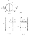
ヘッダーパイプ(2a)は、片面又は両面にろう材層がクラッドされたアルミニウムブレージングシートを、側縁部同士突き合わせ状態(7)に筒状に曲成して構成されたもので、一側面に平坦壁部(9)を有する横断面半円状に成形され、円弧状壁部(10)の周方向中間部に前記側縁突き合わせ部(7)が存在するようになされている。
【0018】
このヘッダーパイプ(2a)の平坦壁部(9)には、その長手方向に間隔的に、チューブ挿入孔(11)…が列設されている。各チューブ挿入孔(11)は、ヘッダーパイプ(2a)の平坦壁部(9)の領域範囲内において周方向にスリット状に延ばされて形成されている。
【0019】
そして、各チューブ挿入孔(11)の周縁部には、その全周にわたって、ヘッダーパイプ(2a)内に突出するバーリング部(12)が形成されている。このバーリング部(12)の内方突出量は、チューブ(1)とヘッダー(2)との接合強度等を考慮して適宜決められる。
【0020】
上記ヘッダーパイプ(2a)は、図3及び図4に示されるようにして製作することができる。
【0021】
即ち、図3(イ)に示されるように、平坦なアルミニウムブレージングシート(13)を用意し、このブレージングシート(13)の幅方向中央部に、図3(ロ)に示されるように、横断面長円状のチューブ挿入孔(11)をピアス加工する。次いで、図3(ハ)に示されるように、このチューブ挿入孔(11)の周縁部の全周に対し、バーリング加工を施し、バーリング部(12)を形成する。このバーリング部(12)を形成した状態におけるチューブ挿入孔(11)の形状・サイズが、チューブ(1)の外周形状・サイズに適合するようになされている。このように平坦な板部にバーリング部(12)を形成すればよいから、チューブ挿入孔(11)の周縁全周にわたるバーリング部(12)を、加工不良、形状不良等の不具合を生じさせることなく、確実性高く、かつ、加工上非常に容易に形成することができる。
【0022】
しかる後、チューブ挿入孔(11)を挟む両側の板部(13a )(13a )に曲げ成形を施す。この曲げ成形においては、まず、図4(ニ)に示されるように、チューブ挿入孔(11)のバーリング部(12)よりも幅方向に所定距離離れた地点を曲げのポイントとして曲げを開始し、それから、図4(ホ)に示されるように、徐々に、バーリング部(12)近傍部へと曲げを及ぼしていき、その曲率を大きくしていく。そして、図4(ヘ)に示されるように、両側の板部(13a )(13a )を円弧状に曲成してその側縁部同士を突き合わせ状態(7)にする。以上により、横断面半円状のヘッダーパイプ(2a)が得られる。このように、ヘッダーパイプ(2a)を横断面半円状とすることにより、これが横断面円形である場合に比べて全周長さが短縮され、ヘッダーパイプ(2a)を材料コスト的に有利に製作していくことができる。
【0023】
熱交換器は、チューブ(1)…、ヘッダーパイプ(2a)、フィン(3)…等を相互仮組状態に組み立て、しかる後、この熱交換器組立体に一括ろう付けを施して全体を接合一体化することにより製作される。
【0024】
まず仮組工程では、図1に示されるように、チューブ(1)の端部がヘッダーパイプ(2a)のチューブ挿入孔(11)内に挿入される。この挿入においては、チューブ挿入孔(11)の周縁部全周に設けられているバーリング部(12)がチューブ(1)の挿入誘導作用を行う。従って、チューブ(1)は、引っかかりや突っ張りを起こすことなく、スムーズにチューブ挿入孔(11)の内方に挿入されていく。特に、バーリング部(12)はチューブ挿入孔(11)の周縁部にその全周にわたって形成されているから、ヘッダーパイプ(2a)に対するチューブ(1)のあらゆる向き・位置における挿入姿勢不良に対処しえてチューブ(1)の端部は適正にヘッダーパイプ(2a)内に誘導されていく。なお、チューブ(1)の端部挿入量は、該端部がバーリング部(12)の先端部よりも若干突出する程度でよいが、深く突出させるか、浅く突出させるか、ほとんど突出させないかは、適宜選択されてよい。
【0025】
一括ろう付け工程では、チューブ(1)とヘッダーパイプ(2a)とは、ヘッダーパイプ(2a)を構成するブレージングシートのろう材により接合される。この接合において、ヘッダー(2)のチューブ挿入孔(11)の周縁部に、その全周にわたって、内方に突出するバーリング部(12)が形成されているものであるから、一括ろう付け中、ろう材は、図2に示されるように、このバーリング部(12)とチューブ(1)との間への楔状ないしは鋭角な隙間によるろう材の引き込み作用、十分なろう材フィレット(14)の形成作用、そして、これらの作用がチューブ(1)の全周にわたって、むらなく、かたよらずに、行われることによって、チューブ(1)とヘッダーパイプ(2a)とは、洩れのない品質良好な接合状態に確実にろう付け接合され、接合部の信頼性が飛躍的に向上される。
【0026】
上記構成の熱交換器では、チューブとして偏平チューブ(1)を採択している。偏平チューブ(1)では、ヘッダー(2)のチューブ挿入孔(11)も上記のように周方向にスリットになり、ヘッダーパイプが横断面円形であると、円弧状の周壁部分にチューブ挿入孔が形成することになる。このようなチューブ挿入孔に全周バーリング部を加工すると、チューブ挿入孔の周方向両端部のバーリングが適正に形成されない、ないしは、適正に形成されにくい。また、平坦な素板にチューブ挿入孔と全周バーリング部を成形し、しかる後この素板を円形パイプ状に曲成する場合には、バーリング部に不本意な変形・歪みを生じ、適正な形状のバーリング部が得られない。これに対し、上記熱交換器では、ヘッダーパイプ(2a)を横断面半円状とし、その平坦壁部にチューブ挿入孔(11)が設けられ、その周縁部全周にバーリング部(12)が加工されていることにより、バーリング部(12)が、チューブ挿入孔(11)の両端部を含めて、全体として歪み等のない形状良好なものに確実かつ非常に容易に形成される。
【0027】
また、上記熱交換器では、ヘッダーパイプ(2a)が、素板(13)をその両側縁部突き合わせ状態(7)に曲成して横断面半円状のパイプ材に成形して構成されたものであるから、素板(13)からヘッダーパイプ(2a)を加工していく過程で、チューブ挿入孔(11)の加工及びバーリング部(12)の加工を行って、ヘッダーパイプ(2a)をその周方向において一部品の構成とすることができ、ヘッダーパイプ(2a)を、平坦壁部と円弧状壁部との複数部品の組み合わせ構成とするような場合に比べて、部品点数を少なくすることができる。
【0028】
しかも、側縁突き合わせ部(7)を円弧状壁部(10)側に設定し、バーリング加工を継ぎ目のない平坦壁部(9)側に定めていることにより、バーリング部(12)を形状精度良好な適正なものに形成することができる。
【0029】
また、ヘッダーパイプ(2a)は、これを横断面円形状に構成すると耐圧性能に優れたものになるが、上記構成のように、これを横断面半円状に構成した場合であっても、バーリング部(12)とチューブ(1)との間の十分なろう材フィレット(14)の形成により、その部分への応力集中は回避され、遜色のない耐圧性能が発揮され、なんら支障はない。特に、チューブ(1)とヘッダーパイプ(2a)との挿入方向の接合部長さは、ろう材フィレット部(14)を含めてヘッダー(2)の肉厚と同じかそれよりも大きく設計しておくのが耐圧性能面で好ましい。
【0030】
上記実施形態に係る熱交換器では、ヘッダーのチューブ挿入孔の周縁部に、その全周にわたって、内方に突出するバーリング部が形成されているものであるから、このバーリング部とチューブとの間へのろう材の引き込み作用、十分なろう材フィレット形成作用、そして、これらの作用がチューブの全周にわたって、むらなく、かたよらずに、行われることによって、チューブとヘッダーとを、洩れのない品質良好な接合状態に確実にろう付け接合することができ、熱交換器の製造歩留まり向上を果たすことができると共に、かかる接合部の信頼性を飛躍的に向上することができる。
【0031】
しかも、バーリング部によるチューブの挿入誘導作用により、ヘッダーのチューブ挿入孔へのチューブ端部の挿入を容易かつ確実に達成することができる。特に、バーリング部はヘッダーのチューブ挿入孔の周縁部にその全周にわたって形成されているから、ヘッダーに対するチューブのあらゆる向き・位置における挿入姿勢不良に対処しえてチューブを非常に容易かつ確実にヘッダーに挿入することができ、チューブ・ヘッダーのろう付け前の組立を不具合の発生なく確実に遂行していくことができる。
【0032】
加えて、ヘッダーは、一側面が平坦な横断面半円状の筒状材からなり、該平坦壁部に形成されたチューブ挿入孔にチューブが挿入された構造である。従って、第1に、ヘッダーにチューブ挿入に必要な幅をもたせたとしてもヘッダー内の容積は半減され、そのため、冷媒が、チューブ内からヘッダー内に移行する際、及び、ヘッダー内からチューブ内に移行する際、に生じうる冷媒の拡大・縮小の変化が抑制されて、冷媒側の圧力損失を低減することができる。
【0033】
以上に、この発明の一実施形態を示したが、この発明は、かかる実施形態に限定されるものではなく、各種変形が可能である。例えば、上記実施形態では、ヘッダーパイプ(2a)は、素板(13)をその両側縁部突き合わせ状態に曲成して横断面半円状のパイプ材に成形して構成されたものであるが、チューブ挿入孔及びバーリング部の設けられた平坦壁材と、円弧状壁材との複数部品を組み合わせた構成とされていてもよい。
【0034】
【発明の効果】
上述の次第で、本発明の熱交換器は、ヘッダーにチューブ挿入に必要な幅をもたせたとしても、ヘッダーが横断面半円状であるがゆえに、チューブがチューブ挿入孔を通じてヘッダー内に挿入された状態における、チューブ側へのヘッダーの突出量は小さく抑えられ、その結果、限られた熱交換器配設スペースの中で、熱交換を行うチューブの占める領域範囲が、ヘッダーに対して相対的に拡大され、そのため、熱交換効率を向上することができる。また、ヘッダーの周囲長を短縮しえて、ヘッダーのための材料コストを減少することができる。
【0035】
しかもまた、チューブ挿入孔は、ヘッダーに備えられた平坦壁部において形成され、この平坦壁部において、チューブ挿入孔全周にわたるバーリング部が形成されているものであるから、このようにチューブ挿入孔の周縁全周にわたるバーリング部を、加工不良、形状不良等の不具合を生じさせることなく、確実性高く、かつ、加工上非常に容易に形成することができる。
【図面の簡単な説明】
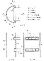
【図1】一実施形態にかかる熱交換器の一括ろう付け前の仮組状態を示すもので、図(イ)はヘッダーとチューブの嵌合部を示す横断面図、図(ロ)は図(イ)のI−I線断面矢視図、図(ハ)は図(イ)のII−II線断面矢視図である。
【図2】一括ろう付け後のヘッダーとチューブとの接合部を示すもので、図(イ)は横断面図、図(ロ)は図(イ)のIII−III線断面矢視図である。
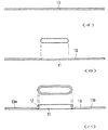
【図3】図(イ)〜図(ハ)はヘッダーパイプの製造工程を順次的に示す横断面図である。
【図4】図(ニ)〜図(ヘ)はヘッダーパイプの製造工程を順次的に示す横断面図である。
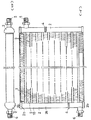
【図5】熱交換器の全体構成を示すもので、図(イ)は正面図、図(ロ)は平面図である。
【図6】従来例を示すもので、図(イ)はヘッダーとチューブの接合部を示す横断面図、図(ロ)は図(イ)のIV−IV線断面矢視図、図(ハ)は図(イ)のV−V線断面矢視図である。
【符号の説明】
1…チューブ
2…ヘッダー
9…平坦壁部
11…チューブ挿入孔
12…バーリング加工部
14…ろう材フィレット[0001]
BACKGROUND OF THE INVENTION
The present invention relates to a heat exchanger made of metal such as aluminum that can be used in a condenser for a car air conditioner, an outdoor heat exchanger for a room air conditioner, an outdoor heat exchanger for a packaged air conditioner, a condenser for a vending machine, and the like , and The present invention relates to a method for manufacturing a header pipe used in the heat exchanger .
[0002]
[Prior art]
For example, as a condenser for a car cooler, a plurality of heat exchange tubes are arranged in parallel at predetermined intervals, and hollow headers are connected to both ends of these tubes in a communicating state, and corrugates are provided between the tubes. A heat exchanger called a so-called multiflow type having a structure in which fins are arranged tends to be used preferably.
[0003]
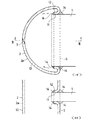
For example, in this type of heat exchanger, the junction structure between the tube and the header has a structure as shown in FIG. In other words, (51)... Are tubes and (52) are headers. The tube (51) is a flat tube having an oval cross-sectional outer peripheral shape, and is composed of a porous extruded material made of aluminum. The header (52) is made of a pipe material having a circular cross section, and is formed by bending an aluminum brazing sheet clad with a brazing material so as to be in a state in which both edge measuring portions are abutted (53). A slit-like tube insertion hole (54) extending in the circumferential direction is formed in the peripheral wall portion of the header (52), and the end of the tube (51) is inserted into the tube insertion hole (54) in an adapted state. The tubes (51) and the header (52) are joined and integrated by batch brazing. Note that the butt portion (53) of the header (52) is also brazed and joined at the same time of the collective brazing.
[0004]
[Problems to be solved by the invention]
However, if the header (52) has a circular cross section as described above, the tube (51) must be inserted deeply into the header (52) when connecting the tube (51) to the header (52). Therefore, the header (52) protrudes inward of the tubes (51), and the effective length of the tubes (51) that contribute to heat exchange is relatively shortened. The area occupied by the tubes (51) for performing heat exchange is narrowed by the presence of the header (52) in the space where the heat exchanger is arranged, which has a problem that heat exchange efficiency is deteriorated. It was.
[0005]
In view of the conventional problems as described above, the present invention can expand the relative region range occupied by the heat exchange tubes in the limited heat exchanger arrangement space, thereby improving the heat exchange efficiency. It is an object of the present invention to provide a heat exchanger having a structure capable of improving the temperature and a method of manufacturing a header pipe used in the heat exchanger .
[0006]
[Means for Solving the Problems]
In the heat exchanger in which the ends of a plurality of tubes are connected in communication with the hollow header, the hollow header is made of a cylindrical material having a semicircular cross section with a flat side surface. A tube insertion hole is formed in the side flat wall portion of the circular cylindrical material, and a burring portion projecting inward is formed on the entire circumference of the peripheral edge portion of the tube insertion hole. The problem is solved by a heat exchanger in which the end of the tube is inserted into the header in a fitted state through the tube insertion hole, and the tube and the header are joined and integrated by brazing.
[0007]
In the above configuration, the header is made of a cylindrical material having a semicircular cross section with one flat side, and the tube is inserted into the tube insertion hole formed in the flat wall portion. Even if the width required for insertion is provided, the header is semicircular in cross section, so the amount of protrusion of the header to the tube side when the tube is inserted into the header through the tube insertion hole can be kept small. As a result, in the limited heat exchanger arrangement space, the area range occupied by the tubes for heat exchange is expanded relative to the header, so that heat exchange is performed efficiently.
[0008]
The header is formed by bending an aluminum brazing sheet clad with a brazing filler metal layer on one side or both sides into a cylindrical shape so that the side edges are in contact with each other. The butt portion may be present.
[0009]
It may be brazed in a state where a wedge-shaped or acute gap is formed between the burring portion and the tube.
[0010]
The length of the joint in the insertion direction between the tube and the header may be equal to or greater than the thickness of the header including the braze filler fillet.
[0011]
The heat exchanger may be used as a condenser for a car cooler.
[0012]
A method of manufacturing a header pipe having a semicircular cross section includes a step of piercing a tube insertion hole having an oval cross section in the center in the width direction of a flat aluminum brazing sheet, and the entire peripheral portion of the tube insertion hole. A process of forming a burring portion on the circumference and forming a burring portion, and after forming the burring portion, start bending at a point separated by a predetermined distance in the width direction from the burring portion of the tube insertion hole, and gradually start bending. And a step of bending the vicinity of the burring portion, increasing the curvature thereof, bending the plate portions on both sides into an arc shape, and bringing the side edges into a butted state.
[0013]
DETAILED DESCRIPTION OF THE INVENTION
Next, an embodiment of the heat exchanger of the present invention will be described.
[0014]
The heat exchanger shown in FIGS. 5A and 5B is a multiflow type heat exchanger used as a condenser for a car cooler or the like. In the heat exchanger, (1)... Are tubes, and (2) and (2) are hollow headers. Note that (3) is a corrugated fin as a fin, (4) is a partition, (5) is a refrigerant inlet pipe, and (6) is the outlet pipe. The partition (4) partitions the inside of the header (2) into a plurality of chambers in the longitudinal direction so that the refrigerant circulates through the tubes (1).
[0015]
In the above heat exchanger constituting member, the tube (1) is made of an extruded material made of aluminum, and is manufactured as a flat tube having an oblong cross section as shown in FIG. A flat tube having a square cross section may be used. The flat tube (1) is formed into a harmonica tube whose interior is partitioned into a plurality of chambers in terms of pressure resistance performance and the like.
[0016]
The header (2) is composed of a header pipe (2a) and a lid member (2b) that closes the end of the header pipe (2a).
[0017]
The header pipe (2a) is composed of an aluminum brazing sheet clad with a brazing filler metal layer on one or both sides, and is bent into a cylindrical shape in a side-to-side contact state (7), flat on one side It is formed in a semicircular cross section having a wall portion (9), and the side edge butting portion (7) is present in the circumferential middle portion of the arc-shaped wall portion (10).
[0018]
Tube insertion holes (11) are arranged in a row in the longitudinal direction of the flat wall portion (9) of the header pipe (2a). Each tube insertion hole (11) is formed to extend in a slit shape in the circumferential direction within the region of the flat wall portion (9) of the header pipe (2a).
[0019]
And the burring part (12) which protrudes in a header pipe (2a) is formed in the peripheral part of each tube insertion hole (11) over the perimeter. The amount of inward protrusion of the burring portion (12) is appropriately determined in consideration of the bonding strength between the tube (1) and the header (2).
[0020]
The header pipe (2a) can be manufactured as shown in FIGS.
[0021]
That is, as shown in FIG. 3 (a), a flat aluminum brazing sheet (13) is prepared, and the brazing sheet (13) is crossed at the center in the width direction as shown in FIG. 3 (b). Pierce the oblong tube insertion hole (11). Next, as shown in FIG. 3C, burring is performed on the entire circumference of the peripheral edge of the tube insertion hole (11) to form the burring part (12). The shape / size of the tube insertion hole (11) in a state where the burring portion (12) is formed is adapted to the outer shape / size of the tube (1). Since it is sufficient to form the burring portion (12) on the flat plate portion in this way, the burring portion (12) over the entire circumference of the tube insertion hole (11) is caused to have defects such as processing defects and shape defects. It can be formed with high reliability and very easily in processing.
[0022]
Thereafter, the plate portions (13a) and (13a) on both sides sandwiching the tube insertion hole (11) are bent. In this bending process, as shown in FIG. 4 (d), first, bending is started at a point that is a predetermined distance in the width direction from the burring part (12) of the tube insertion hole (11). Then, as shown in FIG. 4E, the bending is gradually applied to the vicinity of the burring portion (12) to increase the curvature. Then, as shown in FIG. 4 (f), the plate portions (13a) and (13a) on both sides are bent into an arc shape and the side edges are brought into a butted state (7). Thus, the header pipe (2a) having a semicircular cross section is obtained. Thus, by making the header pipe (2a) into a semicircular cross section, the entire circumference is shortened compared to the case where the header pipe (2a) has a circular cross section, and the header pipe (2a) is advantageous in terms of material cost. It can be produced.
[0023]
As for the heat exchanger, the tubes (1), header pipes (2a), fins (3), etc. are assembled in a mutually temporary assembled state, and then the heat exchanger assembly is collectively brazed and joined together. Manufactured by integrating.
[0024]
First, in the temporary assembly process, as shown in FIG. 1, the end of the tube (1) is inserted into the tube insertion hole (11) of the header pipe (2a). In this insertion, the burring portion (12) provided on the entire periphery of the peripheral edge portion of the tube insertion hole (11) performs an insertion inducing action for the tube (1). Therefore, the tube (1) is smoothly inserted into the tube insertion hole (11) without being caught or stretched. In particular, the burring part (12) is formed on the entire circumference of the peripheral edge of the tube insertion hole (11), so it can cope with poor insertion postures of the tube (1) in all directions and positions with respect to the header pipe (2a). The end of the tube (1) is properly guided into the header pipe (2a). Note that the end insertion amount of the tube (1) may be such that the end protrudes slightly from the tip of the burring portion (12), but whether it protrudes deeply, shallowly, or hardly protrudes. May be appropriately selected.
[0025]
In the collective brazing process, the tube (1) and the header pipe (2a) are joined together by a brazing sheet brazing material constituting the header pipe (2a). In this joining, since the burring portion (12) projecting inward is formed on the entire periphery of the peripheral portion of the tube insertion hole (11) of the header (2), As shown in FIG. 2, the brazing material is drawn into the brazing material between the burring portion (12) and the tube (1) by a wedge-like or acute gap, and a sufficient brazing filler fillet (14) is formed. Actions, and these actions are performed uniformly over the entire circumference of the tube (1), so that the tube (1) and the header pipe (2a) are joined together with good quality without leakage. Thus, the reliability of the joint is dramatically improved.
[0026]
In the heat exchanger of the said structure, the flat tube (1) is employ | adopted as a tube. In the flat tube (1), the tube insertion hole (11) of the header (2) also becomes a slit in the circumferential direction as described above, and if the header pipe is circular in cross section, the tube insertion hole is formed in the arc-shaped peripheral wall portion. Will form. When the entire circumferential burring portion is processed in such a tube insertion hole, burring at both ends in the circumferential direction of the tube insertion hole is not properly formed or is not easily formed properly. In addition, when the tube insertion hole and the entire burring part are formed on a flat base plate, and then the base plate is bent into a circular pipe shape, unintentional deformation / distortion occurs in the burring portion, and an appropriate The shape burring part cannot be obtained. On the other hand, in the heat exchanger, the header pipe (2a) has a semicircular cross section, a tube insertion hole (11) is provided in the flat wall portion, and a burring portion (12) is provided on the entire periphery of the peripheral portion. By being processed, the burring portion (12) including the both ends of the tube insertion hole (11) is surely and very easily formed into a good shape having no distortion as a whole.
[0027]
Further, in the above heat exchanger, the header pipe (2a) is formed by bending the base plate (13) into a state where both side edges are butted (7) and forming a pipe material having a semicircular cross section. Therefore, in the process of processing the header pipe (2a) from the base plate (13), the tube insertion hole (11) and the burring part (12) are processed, and the header pipe (2a) is processed. It can be configured as a single part in the circumferential direction, and the number of parts is reduced compared to the case where the header pipe (2a) is configured by combining multiple parts of a flat wall portion and an arcuate wall portion. be able to.
[0028]
In addition, the side edge butting part (7) is set on the arcuate wall part (10) side, and the burring process is set on the seamless flat wall part (9) side, so that the burring part (12) is shaped accurately. It can be formed into a good and appropriate one.
[0029]
In addition, the header pipe (2a) is excellent in pressure resistance performance when it is configured in a circular cross section, but as in the above configuration, even when it is configured in a semicircular cross section, By forming a sufficient brazing filler fillet (14) between the burring part (12) and the tube (1), stress concentration on that part is avoided, inferior pressure resistance performance is exhibited, and there is no problem. In particular, the length of the joint in the insertion direction between the tube (1) and the header pipe (2a) is designed to be equal to or greater than the thickness of the header (2) including the braze filler fillet (14). Is preferable in terms of pressure resistance.
[0030]
In the heat exchanger according to the above embodiment, since the burring portion protruding inward is formed on the entire periphery of the peripheral portion of the tube insertion hole of the header, the space between the burring portion and the tube is formed. The brazing material pulling action, sufficient brazing fillet forming action, and these actions are performed all over the entire circumference of the tube, so that the tube and the header are not leaked. It is possible to reliably braze and join in a good joined state, to improve the manufacturing yield of the heat exchanger, and to greatly improve the reliability of such a joined portion.
[0031]
Moreover, insertion of the tube end portion into the tube insertion hole of the header can be easily and reliably achieved by the tube insertion inducing action by the burring portion. In particular, since the burring part is formed on the entire circumference of the tube insertion hole in the header, the tube can be used in the header very easily and reliably to cope with poor insertion postures in any orientation and position of the tube relative to the header. It can be inserted, and the assembly of the tube header before brazing can be reliably performed without any trouble.
[0032]
In addition, the header has a structure in which one side is made of a cylindrical material having a semicircular cross section and a tube is inserted into a tube insertion hole formed in the flat wall portion. Therefore, first, even if the header has the necessary width for inserting the tube, the volume in the header is halved. Therefore, when the refrigerant moves from the tube to the header, and from the header to the tube. When the transition is made, the change in expansion / contraction of the refrigerant that can occur is suppressed, and the pressure loss on the refrigerant side can be reduced.
[0033]
As mentioned above, although one Embodiment of this invention was shown, this invention is not limited to this Embodiment, Various deformation | transformation are possible. For example, in the above-described embodiment, the header pipe (2a) is formed by bending the base plate (13) into a state where both side edge portions are butted and forming a pipe material having a semicircular cross section. The flat wall member provided with the tube insertion hole and the burring portion and the arcuate wall member may be combined.
[0034]
【The invention's effect】
Depending on the above, the heat exchanger of the present invention is inserted into the header through the tube insertion hole because the header has a semicircular cross section even if the header has a width necessary for tube insertion. In this state, the protruding amount of the header to the tube side is kept small, and as a result, the area range occupied by the tube for heat exchange in the limited heat exchanger installation space is relative to the header. Therefore, the heat exchange efficiency can be improved. Also, the peripheral length of the header can be shortened, and the material cost for the header can be reduced.
[0035]
Moreover, the tube insertion hole is formed in the flat wall portion provided in the header, and in this flat wall portion, a burring portion is formed over the entire circumference of the tube insertion hole. The burring portion over the entire circumference can be formed with high certainty and very easily in processing without causing defects such as processing failure and shape failure.
[Brief description of the drawings]
BRIEF DESCRIPTION OF DRAWINGS FIG. 1 shows a temporarily assembled state of a heat exchanger according to an embodiment before batch brazing. FIG. 1 (a) is a transverse sectional view showing a fitting portion between a header and a tube, and FIG. II is a cross-sectional view taken along the line II of FIG. 1, and FIG. 6C is a cross-sectional view taken along the line II-II of FIG.
FIGS. 2A and 2B show a joint portion between a header and a tube after batch brazing, in which FIG. 1A is a transverse cross-sectional view, and FIG. .
FIGS. 3A to 3C are cross-sectional views sequentially showing the manufacturing process of the header pipe.
4 (d) to (f) are cross-sectional views sequentially showing the manufacturing process of the header pipe.
FIGS. 5A and 5B show an overall configuration of a heat exchanger, in which FIG. (A) is a front view and FIG. (B) is a plan view.
FIG. 6 shows a conventional example, in which FIG. (A) is a cross-sectional view showing a joint portion between a header and a tube, and (B) is a cross-sectional view taken along the line IV-IV in FIG. ) Is a cross-sectional view taken along line VV in FIG.
[Explanation of symbols]
DESCRIPTION OF
Claims (5)
前記中空ヘッダーは、一側面が平坦な横断面半円状の筒状材からなり、該半円状筒状材の前記側面平坦壁部に、チューブ挿入孔が形成されると共に、該チューブ挿入孔の周縁部に、その全周にわたって、内方に突出するバーリング部が形成され、かつ、該チューブ挿入孔を通じてヘッダー内にチューブの端部が適合状態に挿入され、ろう付けにてチューブとヘッダーとが接合一体化され、
ヘッダーは、片面又は両面にろう材層がクラッドされたアルミニウムブレージングシートを、側縁部同士突き合わせ状態に筒状に曲成して構成され、円弧状壁部の周方向中間部に前記側縁突き合わせ部が存在するものとなされていることを特徴とする熱交換器。In the heat exchanger in which the ends of the plurality of tubes are connected in communication with the hollow header,
The hollow header is made of a cylindrical material having a semicircular cross section with a flat side surface, and a tube insertion hole is formed in the side flat wall portion of the semicircular cylindrical material. A burring portion projecting inward is formed on the entire circumference of the peripheral portion of the tube, and the end portion of the tube is inserted into the header into the header through the tube insertion hole. Is integrated and
The header is formed by bending an aluminum brazing sheet with a brazing material layer clad on one or both sides into a cylindrical shape so that the side edges are in contact with each other. A heat exchanger characterized in that a part is present .
このチューブ挿入孔の周縁部の全周に対し、バーリング加工を施し、バーリング部を形成する工程と、For the entire circumference of the peripheral edge portion of the tube insertion hole, a process of performing burring and forming a burring portion;
バーリング部の形成後、チューブ挿入孔のバーリング部よりも幅方向に所定距離離れた地点を曲げのポイントとして曲げを開始し、徐々に、バーリング部近傍部へと曲げを及ぼしていき、その曲率を大きくし、両側の板部を円弧状に曲成してその側縁部同士を突き合わせ状態にする工程と、After forming the burring part, start bending at a point that is a predetermined distance away from the burring part of the tube insertion hole in the width direction, and gradually bend the vicinity of the burring part. Enlarging, bending the plate portions on both sides into an arc shape and bringing the side edges into a butted state; and
を備えた横断面半円状のヘッダーパイプの製造方法。Of a header pipe having a semicircular cross section with
Priority Applications (1)
| Application Number | Priority Date | Filing Date | Title |
|---|---|---|---|
| JP07252596A JP3880098B2 (en) | 1996-03-27 | 1996-03-27 | Heat exchanger and header pipe manufacturing method |
Applications Claiming Priority (1)
| Application Number | Priority Date | Filing Date | Title |
|---|---|---|---|
| JP07252596A JP3880098B2 (en) | 1996-03-27 | 1996-03-27 | Heat exchanger and header pipe manufacturing method |
Publications (2)
| Publication Number | Publication Date |
|---|---|
| JPH09264689A JPH09264689A (en) | 1997-10-07 |
| JP3880098B2 true JP3880098B2 (en) | 2007-02-14 |
Family
ID=13491846
Family Applications (1)
| Application Number | Title | Priority Date | Filing Date |
|---|---|---|---|
| JP07252596A Expired - Fee Related JP3880098B2 (en) | 1996-03-27 | 1996-03-27 | Heat exchanger and header pipe manufacturing method |
Country Status (1)
| Country | Link |
|---|---|
| JP (1) | JP3880098B2 (en) |
Families Citing this family (5)
| Publication number | Priority date | Publication date | Assignee | Title |
|---|---|---|---|---|
| ATE443840T1 (en) * | 2007-07-17 | 2009-10-15 | Delphi Tech Inc | TUBE SHEET AND PRODUCTION PROCESS THEREOF |
| KR101271140B1 (en) * | 2011-04-08 | 2013-06-04 | 주식회사 유엠하이텍 | Tube-insertion hole for header pipe of regenerator and punch for processing thereof |
| CN106705703A (en) * | 2015-08-03 | 2017-05-24 | 丹佛斯微通道换热器(嘉兴)有限公司 | Heat exchanger |
| WO2018154650A1 (en) * | 2017-02-22 | 2018-08-30 | 三菱電機株式会社 | Heat exchanger |
| JP6919472B2 (en) * | 2017-09-29 | 2021-08-18 | 株式会社デンソー | Heat exchanger |
Family Cites Families (4)
| Publication number | Priority date | Publication date | Assignee | Title |
|---|---|---|---|---|
| JPH0254077U (en) * | 1988-10-03 | 1990-04-19 | ||
| JPH0331068U (en) * | 1989-08-02 | 1991-03-26 | ||
| JP2581387Y2 (en) * | 1992-03-31 | 1998-09-21 | スズキ株式会社 | Capacitor |
| JPH07178486A (en) * | 1993-12-24 | 1995-07-18 | Zexel Corp | Method and device for manufacturing header tank of heat exchanger |
-
1996
- 1996-03-27 JP JP07252596A patent/JP3880098B2/en not_active Expired - Fee Related
Also Published As
| Publication number | Publication date |
|---|---|
| JPH09264689A (en) | 1997-10-07 |
Similar Documents
| Publication | Publication Date | Title |
|---|---|---|
| US5036914A (en) | Vehicle-loaded parallel flow type heat exchanger | |
| US5123483A (en) | Heat exchanger | |
| EP0532794B1 (en) | Manifold and heat exchanger assembly | |
| US5842515A (en) | Heat exchanger and method of manufacturing header pipe for the same | |
| US5785119A (en) | Heat exchanger and method for manufacturing the same | |
| JPH06341788A (en) | Manufacture of heat exchanger and heat exchanger | |
| JP2001041675A (en) | Tube for heat exchanger and heat exchanger | |
| JP2007139416A (en) | Metal plate for producing flat tube, flat tube, and its manufacturing method | |
| JPH06229696A (en) | Heat exchanger | |
| JP3880098B2 (en) | Heat exchanger and header pipe manufacturing method | |
| JP3664783B2 (en) | Condenser | |
| JPH087247Y2 (en) | Heat exchanger | |
| JPH11320005A (en) | Heat exchanger and method of manufacturing the same | |
| JP2020076535A (en) | Heat exchanger and method for manufacturing heat exchanger | |
| JP4300499B2 (en) | Fin coil type heat exchanger and manufacturing method thereof | |
| JPH1038487A (en) | Heat exchanger manufacturing method and heat exchanger | |
| JP2003114094A (en) | Heat exchanger header | |
| JP2000018873A5 (en) | ||
| JPH05164484A (en) | Heat exchanger tube and manufacturing method | |
| JP2000346585A (en) | Heat exchanger | |
| JP3095878B2 (en) | Heat exchanger | |
| JPH11281291A (en) | Heat exchanger | |
| JPH02247498A (en) | Heat exchanger | |
| JPH109791A (en) | Heat exchanger | |
| JPS6314232Y2 (en) |
Legal Events
| Date | Code | Title | Description |
|---|---|---|---|
| A977 | Report on retrieval |
Free format text: JAPANESE INTERMEDIATE CODE: A971007 Effective date: 20060403 |
|
| A131 | Notification of reasons for refusal |
Free format text: JAPANESE INTERMEDIATE CODE: A131 Effective date: 20060620 |
|
| A521 | Written amendment |
Free format text: JAPANESE INTERMEDIATE CODE: A523 Effective date: 20060804 |
|
| TRDD | Decision of grant or rejection written | ||
| A01 | Written decision to grant a patent or to grant a registration (utility model) |
Free format text: JAPANESE INTERMEDIATE CODE: A01 Effective date: 20061017 |
|
| A61 | First payment of annual fees (during grant procedure) |
Free format text: JAPANESE INTERMEDIATE CODE: A61 Effective date: 20061107 |
|
| R150 | Certificate of patent or registration of utility model |
Free format text: JAPANESE INTERMEDIATE CODE: R150 |
|
| RD02 | Notification of acceptance of power of attorney |
Free format text: JAPANESE INTERMEDIATE CODE: R3D02 |
|
| LAPS | Cancellation because of no payment of annual fees |