EP0745547B1 - Sammeleinheit für einen Dokumentensatz und Ausgabesystem - Google Patents
Sammeleinheit für einen Dokumentensatz und Ausgabesystem Download PDFInfo
- Publication number
- EP0745547B1 EP0745547B1 EP96303896A EP96303896A EP0745547B1 EP 0745547 B1 EP0745547 B1 EP 0745547B1 EP 96303896 A EP96303896 A EP 96303896A EP 96303896 A EP96303896 A EP 96303896A EP 0745547 B1 EP0745547 B1 EP 0745547B1
- Authority
- EP
- European Patent Office
- Prior art keywords
- document set
- output
- transport
- transport belt
- roll
- Prior art date
- Legal status (The legal status is an assumption and is not a legal conclusion. Google has not performed a legal analysis and makes no representation as to the accuracy of the status listed.)
- Expired - Lifetime
Links
Images

Classifications
-
- B—PERFORMING OPERATIONS; TRANSPORTING
- B65—CONVEYING; PACKING; STORING; HANDLING THIN OR FILAMENTARY MATERIAL
- B65H—HANDLING THIN OR FILAMENTARY MATERIAL, e.g. SHEETS, WEBS, CABLES
- B65H31/00—Pile receivers
- B65H31/30—Arrangements for removing completed piles
- B65H31/3081—Arrangements for removing completed piles by acting on edge of the pile for moving it along a surface, e.g. by pushing
-
- B—PERFORMING OPERATIONS; TRANSPORTING
- B65—CONVEYING; PACKING; STORING; HANDLING THIN OR FILAMENTARY MATERIAL
- B65H—HANDLING THIN OR FILAMENTARY MATERIAL, e.g. SHEETS, WEBS, CABLES
- B65H29/00—Delivering or advancing articles from machines; Advancing articles to or into piles
- B65H29/12—Delivering or advancing articles from machines; Advancing articles to or into piles by means of the nip between two, or between two sets of, moving tapes or bands or rollers
-
- B—PERFORMING OPERATIONS; TRANSPORTING
- B65—CONVEYING; PACKING; STORING; HANDLING THIN OR FILAMENTARY MATERIAL
- B65H—HANDLING THIN OR FILAMENTARY MATERIAL, e.g. SHEETS, WEBS, CABLES
- B65H29/00—Delivering or advancing articles from machines; Advancing articles to or into piles
- B65H29/16—Delivering or advancing articles from machines; Advancing articles to or into piles by contact of one face only with moving tapes, bands, or chains
-
- B—PERFORMING OPERATIONS; TRANSPORTING
- B65—CONVEYING; PACKING; STORING; HANDLING THIN OR FILAMENTARY MATERIAL
- B65H—HANDLING THIN OR FILAMENTARY MATERIAL, e.g. SHEETS, WEBS, CABLES
- B65H31/00—Pile receivers
- B65H31/30—Arrangements for removing completed piles
- B65H31/3027—Arrangements for removing completed piles by the nip between moving belts or rollers
-
- B—PERFORMING OPERATIONS; TRANSPORTING
- B65—CONVEYING; PACKING; STORING; HANDLING THIN OR FILAMENTARY MATERIAL
- B65H—HANDLING THIN OR FILAMENTARY MATERIAL, e.g. SHEETS, WEBS, CABLES
- B65H2301/00—Handling processes for sheets or webs
- B65H2301/40—Type of handling process
- B65H2301/42—Piling, depiling, handling piles
- B65H2301/421—Forming a pile
- B65H2301/4213—Forming a pile of a limited number of articles, e.g. buffering, forming bundles
-
- B—PERFORMING OPERATIONS; TRANSPORTING
- B65—CONVEYING; PACKING; STORING; HANDLING THIN OR FILAMENTARY MATERIAL
- B65H—HANDLING THIN OR FILAMENTARY MATERIAL, e.g. SHEETS, WEBS, CABLES
- B65H2301/00—Handling processes for sheets or webs
- B65H2301/40—Type of handling process
- B65H2301/42—Piling, depiling, handling piles
- B65H2301/422—Handling piles, sets or stacks of articles
-
- B—PERFORMING OPERATIONS; TRANSPORTING
- B65—CONVEYING; PACKING; STORING; HANDLING THIN OR FILAMENTARY MATERIAL
- B65H—HANDLING THIN OR FILAMENTARY MATERIAL, e.g. SHEETS, WEBS, CABLES
- B65H2301/00—Handling processes for sheets or webs
- B65H2301/50—Auxiliary process performed during handling process
- B65H2301/51—Modifying a characteristic of handled material
- B65H2301/513—Modifying electric properties
- B65H2301/5133—Removing electrostatic charge
-
- B—PERFORMING OPERATIONS; TRANSPORTING
- B65—CONVEYING; PACKING; STORING; HANDLING THIN OR FILAMENTARY MATERIAL
- B65H—HANDLING THIN OR FILAMENTARY MATERIAL, e.g. SHEETS, WEBS, CABLES
- B65H2403/00—Power transmission; Driving means
- B65H2403/20—Belt drives
- B65H2403/21—Timing belts
-
- B—PERFORMING OPERATIONS; TRANSPORTING
- B65—CONVEYING; PACKING; STORING; HANDLING THIN OR FILAMENTARY MATERIAL
- B65H—HANDLING THIN OR FILAMENTARY MATERIAL, e.g. SHEETS, WEBS, CABLES
- B65H2404/00—Parts for transporting or guiding the handled material
- B65H2404/10—Rollers
- B65H2404/11—Details of cross-section or profile
- B65H2404/112—Means for varying cross-section
- B65H2404/1122—Means for varying cross-section for rendering elastically deformable
-
- B—PERFORMING OPERATIONS; TRANSPORTING
- B65—CONVEYING; PACKING; STORING; HANDLING THIN OR FILAMENTARY MATERIAL
- B65H—HANDLING THIN OR FILAMENTARY MATERIAL, e.g. SHEETS, WEBS, CABLES
- B65H2404/00—Parts for transporting or guiding the handled material
- B65H2404/60—Other elements in face contact with handled material
- B65H2404/69—Other means designated for special purpose
- B65H2404/694—Non driven means for pressing the handled material on forwarding or guiding elements
-
- B—PERFORMING OPERATIONS; TRANSPORTING
- B65—CONVEYING; PACKING; STORING; HANDLING THIN OR FILAMENTARY MATERIAL
- B65H—HANDLING THIN OR FILAMENTARY MATERIAL, e.g. SHEETS, WEBS, CABLES
- B65H2801/00—Application field
- B65H2801/03—Image reproduction devices
- B65H2801/06—Office-type machines, e.g. photocopiers
Definitions
- the present invention relates to a compiler tray for use in a high speed printing machine including a document set transport system for delivering document sets to an output tray.
- output copy sheets are accumulated into a stack in a compiler tray for creating a document set which can be delivered to an output tray.
- the output copy sheets are accumulated and aligned in registration with one another in the compiler tray, situated atop a pair of stationary conveyor belts which may be periodically driven through a transport cycle.
- a motor is activated for setting the conveyor belts into transport motion to deliver the document set to the output tray.
- a compiler tray is typically utilized for stacking sheets fed serially thereto in registration with each other so as to provide an neat and uniform document set having uniformly aligned edges.
- the sheets may be registered against a single registration edge or dual registration edges for providing both lateral and longitudinal alignment with respect to the direction of travel of the sheets. It is also desirable to transport or eject a compiled document set from the compiler tray without stapling or otherwise binding the document set. Rapid ejection of the document set is desirable to avoid interrupting the delivery of sheets to the compiler tray. In addition, it is important that no disturbance to the document set occurs during the document set ejection process which may cause misalignment of the previously registered document set.
- US-A-4,541,626 discloses a sheet registration apparatus and device for registering a sheet on a surface against the registration stop including a wiper device having a plurality of resilient blades rotatable about an axis which is generally normal to the support surface.
- the blades extend toward sheet engaging tips which are arranged to wipe across the sheet surface over a limited arc of rotation so as to urge the sheets toward the registration stop.
- the blades are held out of contact with the sheets during part of each revolution by a swash plate having an arcuate opening.
- US-A-4,826,383 discloses a sheet mechanism having drive means for removing compiled sheet sets therefrom, wherein sheets are compiled in a tray against a registration edge and a completed set is ejected with the registration members being retracted by an eject mechanism comprising a continuously rotating drive roller projecting through a base of a tray and a coacting idler roller mounted on a spring arm which is retracted during stacking and then pressed against the top of the completed set to effect ejection.
- the drive roller is a deformable roller having a low coefficient of friction surface.
- US-A-4,989,854 discloses a document set delivery apparatus wherein a set of copy sheets deposited on a surface is delivered positively to an output by engaging the trail edge of the set with at least two hook ended projections intended to overlie the top sheet.
- the hooks prevent the beam strength of the set from lifting the trail edge of the set out of contact with the projections.
- US-A-5,014,582 discloses a sheet handling system including a transport conveyor and a set of separator rollers, wherein the separator rollers operate at a higher speed than the transport conveyor.
- US-A-3,907,275 discloses a sheet stacker in which final output rollers propel sheets from a conveyor, wherein the final output rollers operate at a higher speed than the conveyor.
- a compiler tray for accumulating a plurality of output copy sheets on a support surface to produce a document set.
- the compiler tray includes: a transport belt system including at least one movable belt extending along a curvilinear path defined by a pair of rotatable roll members, with the belt having a portion situated along a substantially common plane with the support surface; characterised by an output drive roll system including at least one output roll for contacting the document set as the document set is being transported via said transport belt system; and means for driving said output roll system at a predetermined speed greater than the speed at which the transport belt system is driven to actively remove the document set from said transport belt system during transport of the document set thereon to the output tray.
- an electrostatographic printing machine including a document set delivery apparatus
- the document set delivery apparatus comprises the compiler tray as set forth above.
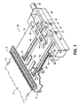
- FIGS. 1 and 2 wherein like reference numerals have been used throughout the drawings to designate identical elements therein, there is shown a compiler tray 10 which has been specifically designed to be incorporated into an automatic electrostatographic printing machine for accumulating and aligning a plurality of individual copy sheets to produce a document print set 4, shown in phantom line in FIG. 2.
- a compiler tray 10 which has been specifically designed to be incorporated into an automatic electrostatographic printing machine for accumulating and aligning a plurality of individual copy sheets to produce a document print set 4, shown in phantom line in FIG. 2.
- the present invention is particularly well suited for use in an automatic electrostatographic printing apparatus, this invention is equally well adapted for use with any number of printing machines and/or other systems which require the compilation of sheets of material and the subsequent transport of such compiled materials.
- an output copy sheet 2 shown in phantom line, is delivered to the compiler tray 10 through the transport motion of the sheet 2 in the direction of arrow 3. Initially, the sheet travels over an inlet member 5 having a plurality of fibers 6 extending therefrom for contacting the underside of the sheet 2 to remove static charges which may have accumulated on the sheet 2 during transport motion thereof and for cleaning particles of dust and other contaminants from the surface thereof.
- each transport belt 16 extends along a curvilinear path defined by a drive roll 18 and a journal roll 15 which are positioned such that at least one portion of each transport belt 16 is located along a plane substantially common with the rigid support surface 12, situated along an opening therein.
- output copy sheets 2 are directed into the tray 10 in seriatum, with the tray 10 and transport belts 16 operating as a depository for collecting and accumulating copy sheets making up a particular document set.
- the copy sheets 2 accumulating in the tray 10 are positioned in abutment with a registration surface which may include a displaceable registration fence comprising at least two pivotable registration fingers 14 sufficiently spaced apart to receive A4 and similar size paper.
- a third finger may also be provided, as illustrated in FIG. 1, to assist in locating output copy sheets of greater dimensions.
- a corner registration apparatus (not shown) may be provided for urging the output copy sheets delivered to the tray to be positioned in abutment with the registration fingers 14.
- a wiper assembly is provided, having a plurality of blades arranged to wipe against the output copy sheets in the compiler tray for urging the sheets into corner registration.
- the registration fingers 14 are pivotably mounted for rotation about an axis, as illustrated in phantom line in FIG. 2, such that the registration fingers 14 may be retracted to allow for ejection of document sets into a collection tray 30 or other suitable collection device such as a set stacker which may have an elevating mechanism for providing increased sheet capacity.
- a stack of sheets 4 is formed to produce an integral document set, as recognized, for example, by a comparison of the number of copy sheets delivered to the compiler tray 10 and the number of sheets in an original document set being copied. It is generally desirable to transport the document set to an output tray 30 where the stack may be stapled or otherwise bound or processed to produce a final document set. It will be understood that the document set could be stapled or otherwise bound in the compiler tray prior to transport to the output tray.
- document set transport or ejection from the compiler tray 10 is effected via a document set delivery apparatus including the previously described transport belts 16 operating in conjunction with an output drive roll system including output rolls 22.
- Each transport belt 16 is engaged with a drive roller 18 which is further coupled to a motor 20, whereby the motor 20 is selectively energized to drive the transport belts 16 in a clockwise direction as viewed in the drawing and indicated by arrow 19.
- each eject transport belt 16 is provided with a resilient eject finger 17 projecting substantially perpendicularly from the exposed surface of the belt 16, as can be seen in FIG. 1, for assisting in the set eject process.
- belt 16 is adapted to remain stationary for a selected period to accumulate a stack of output copy sheets in the compiler tray 10.
- motor 20 is energized such that the eject transport belts 16 are driven along the path of travel between rolls 15,18, the belt being further adapted to be driven by the motor 20 for a predetermined distance.
- each eject finger 17 is transported into contact with the trail edge of the document set while the eject registration fingers 14 are pivoted away from the support surface 12 of the compiler tray 10 as depicted in phantom in FIG. 2, allowing the document set 4 to be transported with the motion of belt 16 in the direction of the output tray 30.
- the eject fingers 17 must be transported to a starting, or so-called "home position", identified by reference numeral 27, in preparation for a subsequent set eject cycle.
- the DC motor 20 which drives the belts 16 is maintained in an energized state in order to continue to transport the eject fingers 17 until they reach a predetermined point, namely the home position 27.
- the continued transport motion of the eject fingers 17 toward this home position 27 tends to cause damage to the alignment of the document set at the trail edge thereof as the eject fingers 17 may travel at such a velocity that they strike the trail edge of the document set while traveling around the circumference of the drive roll 18 and prior to the complete ejection of the document set 4 from the compiler tray.
- the present invention addresses this problem by providing a drive roll system for contacting the document set as it is being transported via the transport belts 16 to actively remove the document set from the transport belts.
- the drive roll system includes a pair of output rolls 22 situated closely adjacent to respective idler rolls 21, forming a a nip therebetween.
- the nip is designed to receive the document set for generating a gripping force thereagainst as the output rolls 22 are rotatably driven, thereby assisting the transport motion of the document set.
- the output rolls are driven at a predetermined speed greater than the speed at which the transport belts 16 are driven. In a preferred embodiment, the output rolls are driven at a speed approximately 20% greater than the speed at which the transport belts are driven for actively removing the document set therefrom.
- FIGS 1 and 2 illustrate two different systems for accomplishing the differential speed drive of the transport belt 16 and the output rolls 22.
- differential speeds are accomplished very simply by driving the transport belt 16 and the output rolls 22 via separate DC drive motors 20 and 24, wherein the output velocity of motor 24 is greater than the output velocity of motor 20.
- differential drive speeds are accomplished via a single motor 20 coupled to both the drive roller 18 and output rolls 22, each coupled via differential gears designed to rotate output rolls 22 at a velocity greater than the velocity of drive roll 18.
- the compiler tray 10 of the present invention also includes an additional feature, namely a retard roll system, which has been shown to be effective in maintaining the registration of the document set as it is transferred from the transport belts 16 to the output rolls 22.
- This retard roll system includes a pair of highly compressible rotatably mounted retard roll members 26 mounted downstream from the registration fingers 14 for contacting the lead edge of the document set 4 as it is being transported via the transport belts 16 and for generating a normal force against the height of the document set as it travels thereunder.
- the retard rolls operate as a lead edge registration device while insuring the integrity of the document set during the transition between the transport belt 16 and the output rolls 22.
- the document set compiler and eject system of the present invention includes a belt transport system 16 as well as an output roll system 21,22, wherein the belt and rolls of each respective system operate in conjunction with one another to provide smooth and effective transport of the document set 4 from the compiler tray 10 to an output tray 30.
- the output rolls 22 are driven at a speed substantially greater than the speed of the transport belts 16 for actively removing the document set 4 from the belts to prevent damage to the trail edge thereof.
- the compiler tray also includes a retard roll system 26 for maintaining the registration of the document set as it is transferred from the transport belts to the output rolls.
Landscapes
- Engineering & Computer Science (AREA)
- Mechanical Engineering (AREA)
- Delivering By Means Of Belts And Rollers (AREA)
- Exposure Or Original Feeding In Electrophotography (AREA)
- Pile Receivers (AREA)
- Registering Or Overturning Sheets (AREA)
Claims (10)
- Kompilierfach (10) zum Sammeln einer Vielzahl von Ausgabe-Kopieblättern (2), die einer Auflagefläche (12) desselben zugeführt werden, um einen Dokumentensatz (4) zu erzeugen, das eine Einrichtung zum Transportieren des Dokumentensatzes zu einem Ausgabefach enthält, und das umfasst:ein Transportbandsystem, das wenigstens ein bewegliches Band (16) enthält, das wahlweise auf einem krummlinigen Weg angetrieben wird, der durch ein Paar drehbarer Rollenelemente (15, 18) gebildet wird, wobei das Band einen Abschnitt aufweist, der in einer im Wesentlichen gemeinsamen Ebene mit der Auflagefläche angeordnet ist; gekennzeichnet durch:ein Ausgabe-Antriebsrollensystem, das wenigstens eine Ausgaberolle (22) enthält, die mit dem Dokumentensatz in Kontakt kommt, wenn der Dokumentensatz über das Transportbandsystem transportiert wird; undeine Einrichtung (20, 24), die das Ausgaberollensystem mit einer vorgegebenen Geschwindigkeit antreibt, die höher ist als eine Geschwindigkeit, mit der das Transportbandsystem angetrieben wird, um den Dokumentensatz während des Transports des Dokumentensatzes zu dem Ausgabefach aktiv von dem Transportbandsystem zu entfemen.
- Kompilierfach nach Anspruch 1, wobei die Antriebseinrichtung (24) in Funktion die wenigstens eine Ausgaberolle mit einer Geschwindigkeit antreibt, die ungefähr 20% höher ist als die Geschwindigkeit, mit der die Transportbänder angetrieben werden, um den Dokumentensatz aktiv von diesen zu entfernen.
- Kompilierfach nach Anspruch 1 oder 2, wobei das Ausgabe-Antriebsrollensystem des Weiteren wenigstens eine Laufrolle (21) enthält, die nahe an der wenigstens einen Ausgaberolle (22) angeordnet ist, so dass ein Spalt entsteht, der den Dokumentensatz (4) aufnimmt und eine Klemmkraft auf den Dokumentensatz ausübt, wenn der Dokumentensatz über das Transportbandsystem transportiert wird.
- Kompilierfach nach einem der Ansprüche 1 bis 3, wobei das wenigstens eine bewegliche Band (16) des Weiteren einen Ausstoßfinger (17) enthält, der sich von dem Band aus erstreckt und mit dem Dokumentensatz an einem Abschnitt in Kontakt kommt, der in der im Wesentlichen gemeinsamen Ebene mit der Auflagefläche angeordnet ist, um mit einer Hinterkante des Dokumentensatzes in Kontakt zu kommen, wenn sich das Band auf dem krummlinigen Weg bewegt, der durch das Paar drehbarer Rollenelemente gebildet wird.
- Kompilierfach nach einem der vorangehenden Ansprüche, wobei das wenigstens eine bewegliche Band über eine ausgewählte Zeit stationär bleibt, um einen Stapel von Ausgabe-Kopieblättem auf der Auflagefläche zu sammeln, und wobei das Band des Weiteren von der Antriebseinrichtung (20) wahlweise angetrieben wird, um Transportbewegung des Transportbandsystems zu bewirken.
- Kompilierfach nach einem der vorangehenden Ansprüche, das des Weiteren eine Ausrichtumzäunung enthält, die wenigstens zwei schwenkbare Ausrichtfinger (14) umfasst, die die Vielzahl von Ausgabe-Kopieblättern auf der Auflagefläche ausrichten, wobei die schwenkbaren Ausrichtfinger um eine Achse herum drehbar angebracht sind, so dass der Dokumentensatz unter dem Einfluss der Transportbewegung des Transportbandsystems von der Auflagefläche transportiert werden kann.
- Kompilierfach nach einem der vorangehenden Ansprüche, wobei die Antriebseinrichtung enthält:einen ersten Motor (20), der mit dem Transportbandsystem verbunden ist und das Transportbandsystem mit einer ersten vorgegebenen Geschwindigkeit antreibt; undeinen zweiten Motor (24), der mit dem Ausgaberollensystem verbunden ist und das Ausgaberollensystem mit einer zweiten vorgegebenen Geschwindigkeit antreibt.
- Kompilierfach nach einem der Ansprüche 1 bis 6, wobei die Antriebseinrichtung enthält:einen einzelnen Motor (20), der sowohl mit dem Transportbandsystem als auch mit dem Ausgaberollensystem verbunden ist; undein Differentialgetriebesystem, das den einzelnen Motor sowohl mit dem Transportbandsystem als auch dem Ausgaberollensystem verbindet, um das Ausgaberollensystem mit einer Geschwindigkeit zu drehen, die höher ist als die Geschwindigkeit des Transportbandsystems.
- Kompilierfach nach einem der vorangehenden Ansprüche, das des Weiteren ein Hemmrollensystem enthält, das wenigstens ein stark zusammendrückbares, drehbar angebrachtes Hemmrollenelement (26) enthält, das mit einer Vorderkante des Dokumentensatz in Kontakt kommt, wenn er über das Transportbandsystem transportiert wird, um die Ausrichtung des Dokumentensatzes während der Überführung von dem Transportbandsystem zu dem Ausgaberollensystem aufrechtzuerhalten.
- Elektrostatografisches Druckgerät, das eine Dokumentensatz-Abgabevorrichtung enthält, die einen Dokumentensatz zu einem Ausgabefach transportiert, wobei die Dokumentensatz-Abgabevorrichtung ein Kompilierfach nach einem der vorangehenden Ansprüche umfasst.
Applications Claiming Priority (2)
| Application Number | Priority Date | Filing Date | Title |
|---|---|---|---|
| US458043 | 1995-06-01 | ||
| US08/458,043 US5623722A (en) | 1995-06-01 | 1995-06-01 | Document set compiler and eject system |
Publications (3)
| Publication Number | Publication Date |
|---|---|
| EP0745547A2 EP0745547A2 (de) | 1996-12-04 |
| EP0745547A3 EP0745547A3 (de) | 1999-02-03 |
| EP0745547B1 true EP0745547B1 (de) | 2002-09-04 |
Family
ID=23819128
Family Applications (1)
| Application Number | Title | Priority Date | Filing Date |
|---|---|---|---|
| EP96303896A Expired - Lifetime EP0745547B1 (de) | 1995-06-01 | 1996-05-30 | Sammeleinheit für einen Dokumentensatz und Ausgabesystem |
Country Status (4)
| Country | Link |
|---|---|
| US (1) | US5623722A (de) |
| EP (1) | EP0745547B1 (de) |
| BR (1) | BR9602575A (de) |
| DE (1) | DE69623392T2 (de) |
Cited By (4)
| Publication number | Priority date | Publication date | Assignee | Title |
|---|---|---|---|---|
| US8708955B2 (en) | 2008-06-02 | 2014-04-29 | Loma Vista Medical, Inc. | Inflatable medical devices |
| US9592119B2 (en) | 2010-07-13 | 2017-03-14 | C.R. Bard, Inc. | Inflatable medical devices |
| US10188436B2 (en) | 2010-11-09 | 2019-01-29 | Loma Vista Medical, Inc. | Inflatable medical devices |
| US10188273B2 (en) | 2007-01-30 | 2019-01-29 | Loma Vista Medical, Inc. | Biological navigation device |
Families Citing this family (13)
| Publication number | Priority date | Publication date | Assignee | Title |
|---|---|---|---|---|
| JP3146336B2 (ja) * | 1995-01-20 | 2001-03-12 | キヤノン株式会社 | シート収納装置及び、シート収納方法及び、画像形成装置 |
| US5857669A (en) * | 1996-10-10 | 1999-01-12 | Bell & Howell Cope Company | Method and apparatus for high speed merging of sheet material onto a transport from the side |
| US5915689A (en) * | 1997-08-19 | 1999-06-29 | Xerox Corporation | Quick change swiper blades |
| JP3477353B2 (ja) | 1997-11-13 | 2003-12-10 | シャープ株式会社 | シート後処理装置 |
| US6293544B1 (en) * | 1999-12-22 | 2001-09-25 | Xerox Corporation | Apparatus and method for registering and conveying a compiled set of sheets |
| US6386537B1 (en) | 2000-04-13 | 2002-05-14 | Pitney Bowes Inc. | Sheet accumulator with diverting mechanisms |
| ES2225373T3 (es) * | 2001-09-12 | 2005-03-16 | SEGBERT GMBH & CO. KG | Dispositivo para la alineacion y transporte de paquetes de productos impresos apilados sueltos. |
| US7050734B2 (en) * | 2004-03-25 | 2006-05-23 | Lexmark International, Inc. | Method of determining a relative speed between independently driven members in an image forming apparatus |
| US7149449B2 (en) * | 2004-05-13 | 2006-12-12 | Lexmark International, Inc. | Method of determining a relative speed between independently driven members in an image forming apparatus |
| JP4495079B2 (ja) * | 2005-12-26 | 2010-06-30 | 東芝テック株式会社 | 用紙後処理装置 |
| US7862026B2 (en) * | 2007-06-19 | 2011-01-04 | Kabushiki Kaisha Toshiba | Sheet post-processing apparatus and sheet post-processing method |
| US8260188B2 (en) * | 2009-06-19 | 2012-09-04 | Kabushiki Kaisha Toshiba | Image erasing apparatus and image erasing method |
| JP5602325B1 (ja) * | 2014-04-10 | 2014-10-08 | 株式会社東京機械製作所 | 集積ユニット及び印刷物作成装置 |
Family Cites Families (10)
| Publication number | Priority date | Publication date | Assignee | Title |
|---|---|---|---|---|
| GB1436341A (en) * | 1973-04-03 | 1976-05-19 | Masson Scott Thrissell Eng Ltd | Speed control apparatus |
| US4541626A (en) * | 1982-07-07 | 1985-09-17 | Xerox Corporation | Sheet registration apparatus and device |
| US4826383A (en) * | 1982-07-07 | 1989-05-02 | Xerox Corporation | A sheet mechanism having drive means for removing compiled sheet sets therefrom |
| GB2206866B (en) * | 1987-06-26 | 1992-01-15 | Xerox Corp | Document set delivery apparatus |
| GB8729442D0 (en) * | 1987-12-17 | 1988-02-03 | Chambon Ltd | Carton blank die-cutting machine assembly |
| US5048812A (en) * | 1988-11-03 | 1991-09-17 | Prime Technology | Sheet feeding apparatus |
| US5088590A (en) * | 1990-03-30 | 1992-02-18 | Marquip, Inc. | System for changing the speed of conveyed sheets while holding register |
| US5050859A (en) * | 1990-06-18 | 1991-09-24 | Eastman Kodak Company | Variable speed sheet transport system |
| GB2259501B (en) * | 1991-09-11 | 1995-04-12 | Xerox Corp | Electrostatographic reproducing machine |
| US5166735A (en) * | 1992-06-05 | 1992-11-24 | Xerox Corporation | Sheet buckle sensing |
-
1995
- 1995-06-01 US US08/458,043 patent/US5623722A/en not_active Expired - Lifetime
-
1996
- 1996-05-30 DE DE69623392T patent/DE69623392T2/de not_active Expired - Fee Related
- 1996-05-30 EP EP96303896A patent/EP0745547B1/de not_active Expired - Lifetime
- 1996-05-31 BR BR9602575A patent/BR9602575A/pt not_active IP Right Cessation
Cited By (6)
| Publication number | Priority date | Publication date | Assignee | Title |
|---|---|---|---|---|
| US10188273B2 (en) | 2007-01-30 | 2019-01-29 | Loma Vista Medical, Inc. | Biological navigation device |
| US8708955B2 (en) | 2008-06-02 | 2014-04-29 | Loma Vista Medical, Inc. | Inflatable medical devices |
| US9186488B2 (en) | 2008-06-02 | 2015-11-17 | Loma Vista Medical, Inc. | Method of making inflatable medical devices |
| US9504811B2 (en) | 2008-06-02 | 2016-11-29 | Loma Vista Medical, Inc. | Inflatable medical devices |
| US9592119B2 (en) | 2010-07-13 | 2017-03-14 | C.R. Bard, Inc. | Inflatable medical devices |
| US10188436B2 (en) | 2010-11-09 | 2019-01-29 | Loma Vista Medical, Inc. | Inflatable medical devices |
Also Published As
| Publication number | Publication date |
|---|---|
| DE69623392T2 (de) | 2003-05-22 |
| EP0745547A3 (de) | 1999-02-03 |
| DE69623392D1 (de) | 2002-10-10 |
| EP0745547A2 (de) | 1996-12-04 |
| US5623722A (en) | 1997-04-22 |
| BR9602575A (pt) | 1998-10-06 |
Similar Documents
| Publication | Publication Date | Title |
|---|---|---|
| EP0745547B1 (de) | Sammeleinheit für einen Dokumentensatz und Ausgabesystem | |
| US5188353A (en) | Disk stacker including tamping mechanism capable of cross-direction offsetting | |
| EP0528493B1 (de) | Rollenakkumulator für Bogen | |
| US6267372B1 (en) | Device for separating sheets in a pile | |
| JP3757590B2 (ja) | 紙搬送装置及び紙搬送方法 | |
| US5114135A (en) | Disk stacker including registration assist device | |
| AU649590B2 (en) | Paper sheet feeding apparatus | |
| US7168696B2 (en) | Apparatus and method for separating flat parceled goods | |
| US5545000A (en) | Automatic eject finger retractor for document set eject system | |
| GB2261872A (en) | Buckle chute folder. | |
| US5145167A (en) | Disk stacker including trail edge transport belt for stacking short and long sheets | |
| EP0768260B1 (de) | Vorrichtung zum Handhaben von Papier | |
| US5065996A (en) | Disk stacker including movable gate for insertion of sheets into disk slots | |
| JP2008169044A (ja) | 順次重ねられたシートのスタックを整列するための装置と方法 | |
| EP0133945A1 (de) | Druckbogenhandhabungsvorrichtung | |
| EP0302169A2 (de) | Hochgeschwindigkeitsablegevorrichtung für gedrückte Gegenstände | |
| CA2203714C (en) | Device for feeding printed product to a further processing point | |
| US7581726B2 (en) | Device and method for collecting successively fed flat objects | |
| EP0876981A2 (de) | Papierstapelvorrichtung mit Einrichtung zur Bildung von versetzten Stapeln | |
| JPH01242360A (ja) | 紙葉類堆積繰出し機構 | |
| JP2009067557A (ja) | シート処理装置 | |
| JPS6224340B2 (de) | ||
| US6712354B1 (en) | Accumulator apparatus and method having improved sheet registration | |
| JPH0741199A (ja) | 用紙さばき方式 | |
| JP3631071B2 (ja) | 画像形成装置に用いる後処理装置 |
Legal Events
| Date | Code | Title | Description |
|---|---|---|---|
| PUAI | Public reference made under article 153(3) epc to a published international application that has entered the european phase |
Free format text: ORIGINAL CODE: 0009012 |
|
| AK | Designated contracting states |
Kind code of ref document: A2 Designated state(s): DE FR GB |
|
| PUAL | Search report despatched |
Free format text: ORIGINAL CODE: 0009013 |
|
| AK | Designated contracting states |
Kind code of ref document: A3 Designated state(s): DE FR GB |
|
| 17P | Request for examination filed |
Effective date: 19990803 |
|
| 17Q | First examination report despatched |
Effective date: 20001103 |
|
| GRAG | Despatch of communication of intention to grant |
Free format text: ORIGINAL CODE: EPIDOS AGRA |
|
| GRAG | Despatch of communication of intention to grant |
Free format text: ORIGINAL CODE: EPIDOS AGRA |
|
| GRAH | Despatch of communication of intention to grant a patent |
Free format text: ORIGINAL CODE: EPIDOS IGRA |
|
| GRAH | Despatch of communication of intention to grant a patent |
Free format text: ORIGINAL CODE: EPIDOS IGRA |
|
| GRAA | (expected) grant |
Free format text: ORIGINAL CODE: 0009210 |
|
| AK | Designated contracting states |
Kind code of ref document: B1 Designated state(s): DE FR GB |
|
| REG | Reference to a national code |
Ref country code: GB Ref legal event code: FG4D |
|
| REF | Corresponds to: |
Ref document number: 69623392 Country of ref document: DE Date of ref document: 20021010 |
|
| ET | Fr: translation filed | ||
| PLBE | No opposition filed within time limit |
Free format text: ORIGINAL CODE: 0009261 |
|
| STAA | Information on the status of an ep patent application or granted ep patent |
Free format text: STATUS: NO OPPOSITION FILED WITHIN TIME LIMIT |
|
| 26N | No opposition filed |
Effective date: 20030605 |
|
| PGFP | Annual fee paid to national office [announced via postgrant information from national office to epo] |
Ref country code: FR Payment date: 20040510 Year of fee payment: 9 |
|
| PGFP | Annual fee paid to national office [announced via postgrant information from national office to epo] |
Ref country code: GB Payment date: 20040526 Year of fee payment: 9 |
|
| PGFP | Annual fee paid to national office [announced via postgrant information from national office to epo] |
Ref country code: DE Payment date: 20040610 Year of fee payment: 9 |
|
| PG25 | Lapsed in a contracting state [announced via postgrant information from national office to epo] |
Ref country code: GB Free format text: LAPSE BECAUSE OF NON-PAYMENT OF DUE FEES Effective date: 20050530 |
|
| PG25 | Lapsed in a contracting state [announced via postgrant information from national office to epo] |
Ref country code: DE Free format text: LAPSE BECAUSE OF NON-PAYMENT OF DUE FEES Effective date: 20051201 |
|
| GBPC | Gb: european patent ceased through non-payment of renewal fee |
Effective date: 20050530 |
|
| PG25 | Lapsed in a contracting state [announced via postgrant information from national office to epo] |
Ref country code: FR Free format text: LAPSE BECAUSE OF NON-PAYMENT OF DUE FEES Effective date: 20060131 |
|
| REG | Reference to a national code |
Ref country code: FR Ref legal event code: ST Effective date: 20060131 |