EP0744934B1 - Fussausgang für sitzbett - Google Patents
Fussausgang für sitzbett Download PDFInfo
- Publication number
- EP0744934B1 EP0744934B1 EP95911577A EP95911577A EP0744934B1 EP 0744934 B1 EP0744934 B1 EP 0744934B1 EP 95911577 A EP95911577 A EP 95911577A EP 95911577 A EP95911577 A EP 95911577A EP 0744934 B1 EP0744934 B1 EP 0744934B1
- Authority
- EP
- European Patent Office
- Prior art keywords
- bed
- foot
- panel
- frame
- patient
- Prior art date
- Legal status (The legal status is an assumption and is not a legal conclusion. Google has not performed a legal analysis and makes no representation as to the accuracy of the status listed.)
- Expired - Lifetime
Links
- 210000000689 upper leg Anatomy 0.000 claims abstract description 30
- 238000000034 method Methods 0.000 claims description 7
- 238000005096 rolling process Methods 0.000 claims description 4
- 230000000630 rising effect Effects 0.000 claims description 2
- 238000003032 molecular docking Methods 0.000 abstract description 4
- 230000007246 mechanism Effects 0.000 description 9
- 230000000694 effects Effects 0.000 description 3
- 210000002414 leg Anatomy 0.000 description 2
- 238000002560 therapeutic procedure Methods 0.000 description 2
- 235000004443 Ricinus communis Nutrition 0.000 description 1
- 240000000528 Ricinus communis Species 0.000 description 1
- 238000006243 chemical reaction Methods 0.000 description 1
- 230000000266 injurious effect Effects 0.000 description 1
- 238000012986 modification Methods 0.000 description 1
- 230000004048 modification Effects 0.000 description 1
Images


Classifications
-
- A—HUMAN NECESSITIES
- A61—MEDICAL OR VETERINARY SCIENCE; HYGIENE
- A61G—TRANSPORT, PERSONAL CONVEYANCES, OR ACCOMMODATION SPECIALLY ADAPTED FOR PATIENTS OR DISABLED PERSONS; OPERATING TABLES OR CHAIRS; CHAIRS FOR DENTISTRY; FUNERAL DEVICES
- A61G7/00—Beds specially adapted for nursing; Devices for lifting patients or disabled persons
- A61G7/10—Devices for lifting patients or disabled persons, e.g. special adaptations of hoists thereto
- A61G7/16—Devices for lifting patients or disabled persons, e.g. special adaptations of hoists thereto converting a lying surface into a chair
-
- A—HUMAN NECESSITIES
- A61—MEDICAL OR VETERINARY SCIENCE; HYGIENE
- A61G—TRANSPORT, PERSONAL CONVEYANCES, OR ACCOMMODATION SPECIALLY ADAPTED FOR PATIENTS OR DISABLED PERSONS; OPERATING TABLES OR CHAIRS; CHAIRS FOR DENTISTRY; FUNERAL DEVICES
- A61G7/00—Beds specially adapted for nursing; Devices for lifting patients or disabled persons
- A61G7/002—Beds specially adapted for nursing; Devices for lifting patients or disabled persons having adjustable mattress frame
- A61G7/008—Beds specially adapted for nursing; Devices for lifting patients or disabled persons having adjustable mattress frame tiltable around longitudinal axis, e.g. for rolling
-
- A—HUMAN NECESSITIES
- A61—MEDICAL OR VETERINARY SCIENCE; HYGIENE
- A61G—TRANSPORT, PERSONAL CONVEYANCES, OR ACCOMMODATION SPECIALLY ADAPTED FOR PATIENTS OR DISABLED PERSONS; OPERATING TABLES OR CHAIRS; CHAIRS FOR DENTISTRY; FUNERAL DEVICES
- A61G7/00—Beds specially adapted for nursing; Devices for lifting patients or disabled persons
- A61G7/002—Beds specially adapted for nursing; Devices for lifting patients or disabled persons having adjustable mattress frame
- A61G7/015—Beds specially adapted for nursing; Devices for lifting patients or disabled persons having adjustable mattress frame divided into different adjustable sections, e.g. for Gatch position
-
- A—HUMAN NECESSITIES
- A61—MEDICAL OR VETERINARY SCIENCE; HYGIENE
- A61G—TRANSPORT, PERSONAL CONVEYANCES, OR ACCOMMODATION SPECIALLY ADAPTED FOR PATIENTS OR DISABLED PERSONS; OPERATING TABLES OR CHAIRS; CHAIRS FOR DENTISTRY; FUNERAL DEVICES
- A61G7/00—Beds specially adapted for nursing; Devices for lifting patients or disabled persons
- A61G7/05—Parts, details or accessories of beds
- A61G7/0506—Head or foot boards
-
- A—HUMAN NECESSITIES
- A61—MEDICAL OR VETERINARY SCIENCE; HYGIENE
- A61G—TRANSPORT, PERSONAL CONVEYANCES, OR ACCOMMODATION SPECIALLY ADAPTED FOR PATIENTS OR DISABLED PERSONS; OPERATING TABLES OR CHAIRS; CHAIRS FOR DENTISTRY; FUNERAL DEVICES
- A61G7/00—Beds specially adapted for nursing; Devices for lifting patients or disabled persons
- A61G7/05—Parts, details or accessories of beds
- A61G7/0507—Side-rails
- A61G7/0512—Side-rails characterised by customised length
- A61G7/0513—Side-rails characterised by customised length covering particular sections of the bed, e.g. one or more partial side-rail sections along the bed
- A61G7/0514—Side-rails characterised by customised length covering particular sections of the bed, e.g. one or more partial side-rail sections along the bed mounted to individual mattress supporting frame sections
-
- A—HUMAN NECESSITIES
- A61—MEDICAL OR VETERINARY SCIENCE; HYGIENE
- A61G—TRANSPORT, PERSONAL CONVEYANCES, OR ACCOMMODATION SPECIALLY ADAPTED FOR PATIENTS OR DISABLED PERSONS; OPERATING TABLES OR CHAIRS; CHAIRS FOR DENTISTRY; FUNERAL DEVICES
- A61G7/00—Beds specially adapted for nursing; Devices for lifting patients or disabled persons
- A61G7/05—Parts, details or accessories of beds
- A61G7/0527—Weighing devices
-
- A—HUMAN NECESSITIES
- A61—MEDICAL OR VETERINARY SCIENCE; HYGIENE
- A61G—TRANSPORT, PERSONAL CONVEYANCES, OR ACCOMMODATION SPECIALLY ADAPTED FOR PATIENTS OR DISABLED PERSONS; OPERATING TABLES OR CHAIRS; CHAIRS FOR DENTISTRY; FUNERAL DEVICES
- A61G7/00—Beds specially adapted for nursing; Devices for lifting patients or disabled persons
- A61G7/05—Parts, details or accessories of beds
- A61G7/053—Aids for getting into, or out of, bed, e.g. steps, chairs, cane-like supports
-
- A—HUMAN NECESSITIES
- A61—MEDICAL OR VETERINARY SCIENCE; HYGIENE
- A61H—PHYSICAL THERAPY APPARATUS, e.g. DEVICES FOR LOCATING OR STIMULATING REFLEX POINTS IN THE BODY; ARTIFICIAL RESPIRATION; MASSAGE; BATHING DEVICES FOR SPECIAL THERAPEUTIC OR HYGIENIC PURPOSES OR SPECIFIC PARTS OF THE BODY
- A61H3/00—Appliances for aiding patients or disabled persons to walk about
- A61H3/04—Wheeled walking aids for patients or disabled persons
-
- A—HUMAN NECESSITIES
- A61—MEDICAL OR VETERINARY SCIENCE; HYGIENE
- A61G—TRANSPORT, PERSONAL CONVEYANCES, OR ACCOMMODATION SPECIALLY ADAPTED FOR PATIENTS OR DISABLED PERSONS; OPERATING TABLES OR CHAIRS; CHAIRS FOR DENTISTRY; FUNERAL DEVICES
- A61G7/00—Beds specially adapted for nursing; Devices for lifting patients or disabled persons
- A61G7/002—Beds specially adapted for nursing; Devices for lifting patients or disabled persons having adjustable mattress frame
- A61G7/005—Beds specially adapted for nursing; Devices for lifting patients or disabled persons having adjustable mattress frame tiltable around transverse horizontal axis, e.g. for Trendelenburg position
-
- A—HUMAN NECESSITIES
- A61—MEDICAL OR VETERINARY SCIENCE; HYGIENE
- A61G—TRANSPORT, PERSONAL CONVEYANCES, OR ACCOMMODATION SPECIALLY ADAPTED FOR PATIENTS OR DISABLED PERSONS; OPERATING TABLES OR CHAIRS; CHAIRS FOR DENTISTRY; FUNERAL DEVICES
- A61G7/00—Beds specially adapted for nursing; Devices for lifting patients or disabled persons
- A61G7/002—Beds specially adapted for nursing; Devices for lifting patients or disabled persons having adjustable mattress frame
- A61G7/012—Beds specially adapted for nursing; Devices for lifting patients or disabled persons having adjustable mattress frame raising or lowering of the whole mattress frame
-
- A—HUMAN NECESSITIES
- A61—MEDICAL OR VETERINARY SCIENCE; HYGIENE
- A61G—TRANSPORT, PERSONAL CONVEYANCES, OR ACCOMMODATION SPECIALLY ADAPTED FOR PATIENTS OR DISABLED PERSONS; OPERATING TABLES OR CHAIRS; CHAIRS FOR DENTISTRY; FUNERAL DEVICES
- A61G7/00—Beds specially adapted for nursing; Devices for lifting patients or disabled persons
- A61G7/02—Beds specially adapted for nursing; Devices for lifting patients or disabled persons with toilet conveniences, or specially adapted for use with toilets
-
- A—HUMAN NECESSITIES
- A61—MEDICAL OR VETERINARY SCIENCE; HYGIENE
- A61G—TRANSPORT, PERSONAL CONVEYANCES, OR ACCOMMODATION SPECIALLY ADAPTED FOR PATIENTS OR DISABLED PERSONS; OPERATING TABLES OR CHAIRS; CHAIRS FOR DENTISTRY; FUNERAL DEVICES
- A61G7/00—Beds specially adapted for nursing; Devices for lifting patients or disabled persons
- A61G7/05—Parts, details or accessories of beds
Definitions
- This invention relates to a hospital bed that is convertible to a chair.
- the structure of the present invention is primarily useful for facilitating getting a patient from a supine position on the bed to a standing and/or walking position or into a wheelchair or other ambulatory assisting device.
- two nurses or other health care providers are preferably employed in assisting a patient in moving from a supine position to a standing position. This is particularly true for a patient who has been in the supine position for a long period of time. In many instances, the patient in that condition simply does not want to stand because it is painful.
- the bed is lowered and the side rails of the bed are dropped.
- the patient is then pivoted or swung through approximately 90° so that the patient's legs hang over the side of the bed.
- the patient's feet likely will not rest firmly on the floor. Therefore, in addition to experiencing discomfort or pain, the patient is apprehensive about sliding off the bed without knowing when his feet will touch the floor.
- the health care providers assist the patient in getting his feet on the floor as he slides off the bed.
- the attendants are unable to lift the patient directly since they are at the edge of the bed and the patient's weight is centered inward of the edge of the bed. If the patient should start to fall, the attendants must hold the patient firmly while at the same time bracing themselves in a somewhat awkward position. The resulting situation is potentially injurious not only for the patient, but for the attendants as well.
- U.S. Patent No. 4,862,529 discloses a bed which is convertible to a chair and has a retracting frame mounted on a fixed frame.
- a patient support surface is formed by serially connected panels with a seat panel being fixed to the retracting frame. Movement of the retracting frame toward the foot end of the bed causes a head panel to rise and a leg panel to drop, thereby creating a chair configuration.
- a foot panel of the bed underlies the patient's feet when in the chair position.
- a so-called "false floor” is created for the patient's feet, thereby preventing the patient from placing his feet directly on the floor to exit to stand and exit the bed.
- the position of the foot panel in the chair configuration blocks access to patient and bed and prevents easily transferring the patient from the bed to a wheelchair or other ambulatory assisting device.
- EP-A-0178951 describes a hospital bed with a frame end and a platform carried on the frame including a head panel and a foot section.
- the foot section comprises a plurality of transverse slats linked by a pair of chains.
- the platform can be moved towards the foot end of the bed, the head panel pivoted up and the slats rolled round under the frame to convert the bed to a chair configuration.
- One objective of this invention has been to provide a hospital bed convertible to a chair which permits the patient to conveniently exit the bed from the foot end thereof.
- Another objective of the invention has been to provide a bed convertible to a chair in which the patient's feet contact the floor directly when exiting the bed in the chair configuration.
- Yet another objective of this invention has been to provide a hospital bed convertible to a chair in which an area at the foot end of the bed is vacated in the chair configuration to provide a space for docking a wheelchair or other ambulatory assisting device.
- a hospital bed with a frame mounted on a base and a patient support platform mounted on the frame.
- the patient support platform includes a foot panel having a pivoting portion and a collapsing, or translating, portion which collapses, or translates, as the pivoting portion is pivoted.
- a foot egress chair bed having a generally planar bed position and convertible to a chair position and permitting patient egress from the foot end thereof
- a base a frame mounted on said base, and a patient support platform mounted on said frame and including at least head and foot panels, said head panel being mounted for pivotal movement relative to said frame to a raised position when converting said bed to the chair position
- said foot panel includes a pivoting portion and a collapsing portion, said collapsing portion extending from and retracting toward said pivoting portion as said pivoting portion pivots upwardly and downwardly, respectively.
- a method of patient egress from a foot end of a bed converted to a chair including providing a bed with a base, a frame mounted on said base, a patient support platform mounted on said frame and including at least head and foot panels, said head panel being mounted for pivotal movement relative to said frame to a raised position when converting said bed to the chair position, characterised in that said foot panel includes a pivoting portion and a collapsing portion, said collapsing portion extending from and retracting toward said pivoting portion as said pivoting portion pivots upwardly and downwardly, respectively.
- the bed of the present invention does not have a panel or any other structure underlying the patient's feet when it is in the chair configuration, unlike many prior beds which are convertible to chairs.
- a patient's feet rest directly on the floor surface when the bed is converted to the chair configuration, thereby avoiding patient insecurity or the inconvenience associated with a "false floor” effect.
- an area is vacated at the foot end of the bed in the chair configuration to provide space for docking a wheelchair, motorised scooter, motorised walker, exerciser or other patient therapy/rehabilitation apparatus. This is accomplished without however physically removing the foot section of the patient support from the bed.
- the platform is provided with a series of interconnected head, seat, thigh and foot panels which are hinged at their respective interfaces.
- the patient support platform and panels translate longitudinally with respect to the hospital bed frame.
- the patient support platform is movable longitudinally relative to the bed base by a hydraulic cylinder.
- the seat panel moves atop the bed frame by rollers mounted to and underlying the seat panel.
- the patient support platform In converting the bed to the chair configuration, the patient support platform is lowered to a lowermost position and then translated toward the foot end of the bed.
- the foot panel pivots downwardly to a generally vertical attitude rather than pivoting along a second axis to underlie the patient's feet.
- a portion of the foot support panel collapses into itself as the panel pivots downwardly, thereby providing space at the foot end of the bed.
- a central section of the foot panel includes a pivoting portion and a collapsing portion which telescopes into and out of the pivoting portion by approximately 13 inches.
- the collapsing portion is smaller in cross-section than the pivoting portion to allow for telescoping, and is spring biased relative to the pivoting portion toward an extended position.
- a pair of links pivotally connect the pivoting portion of the foot panel to the bed frame.
- Rollers are mounted on either side of the bed frame and under the lateral edges of the pivoting portion of the foot panel. Movement of the patient support platform with the hydraulic cylinder toward the foot end of the bed causes the pivoting portion of the foot panel to drop to a generally vertical position due to the connection of the foot end of the pivoting portion of the foot panel to the bed frame via the pivot links and the traveling fulcrum effect of the rollers underlying the pivoting portion.
- a block rides against a roller underlying the foot panel which is connected to the head end of the collapsing portion.
- the block is moved away from the foot end of the foot panel to retract the collapsible portion into the pivoting portion of the foot panel. Movement of the patient support platform toward the head end of the bed moves the block toward the foot end of the bed.
- the collapsing portion is spring biased relative to the pivoting portion toward an outwardly extended position allowing the collapsing portion to project out of the pivoting portion.
- a section of the bed frame underlying the foot panel is generally U-shaped with the open end of the U facing toward the foot end of the bed.
- a lateral section of the foot panel is pivotally connected to the thigh panel at its head end on each side of the central section.
- Each lateral section of the foot panel is supported by one of the arms of the U-shaped section of the bed frame.
- the lateral sections of the foot panel can pivot relative to the thigh panel as is required if the thigh panel is pivoted upwardly relative to the seat panel.
- the foot end of the lateral sections of the foot panel remain atop the arms of the U-shaped frame section and do not pivot downwardly through the frame as does the central section of the foot panel.
- a pivoting footboard is mounted at the outer end of each arm of the U-shaped frame section.
- Each footboard can be outfitted with the various controls which are currently offered on existing hospital bed footboards.
- the footboards function as a typical footboard when pivoted to be generally collinear with each other at the foot end edge of the bed in an end-to-end configuration.
- the footboards as handholds aid the patient in rising from a seated position to a standing position and vice versa.
- the pivoting feature of the footboards allows for the entire foot section defined by the U-shaped section of the frame to be evacuated for docking therapy/rehabilitation accessories to the bed.
- a patient lift mechanism raises the patient support platform to aid the patient in standing or exiting the bed.
- the patient lift mechanism includes a four bar linkage connecting the frame to the base and a hydraulic cylinder connected to the linkage and the base.
- the bed of this invention can be utilized in other applications, as for example, a birthing bed in which case the lateral sections of the foot panel would include stirrups.
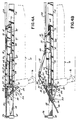
- a hospital bed 10 has a base 12 and a frame 14 mounted on the base 12.
- the hospital bed 10 has castors 16 for movement of the bed 10 about the hospital.
- the bed 10 has a patient support platform 18 underlying a mattress 20 on which a patient 22 is situated. At least a portion of the mattress 20 is preferably inflated.
- the hospital bed 10 has patient side guards 24 and foot guards 26 for protection of the patient 22 situated atop the bed 10.
- the patient support platform 18 can be converted to and between a generally horizontal bed configuration and a chair configuration as shown in Fig. 2.
- the patient support platform 18 consists of serially hinged head 28, seat 30, thigh 32 and foot 34 panels. Each panel is pivotally attached to the adjoining panel as by pins or other suitable mechanisms well known in the art.
- the foot panel 34 consists of a central section 38 and a pair of lateral sections 40, 40, one of which is pivotally mounted to the thigh panel 32 on each lateral side of the central section 38 as by a pin or bar 42 as shown in Fig. 3.
- the central section 38 of the foot panel 34 consists of a pivoting portion 44 which is likewise pinned to the thigh panel 32 by the bar or pin 42 and a collapsing portion 46 which is smaller in cross-section than the pivoting portion 44 for telescoping into and out of a cavity 48 within the pivoting portion 44.
- the collapsing portion 46 is biased by a spring 50 connected at a first end to a crossbar 52 secured to the collapsing portion 46 and at a second end to a crossbar 54 secured to and underlying the pivoting portion 44.
- the collapsing portion 46 extends approximately 13 inches out of the pivoting portion 44 of the foot panel 34 in the bed configuration.
- the frame 14 of the bed 10 includes a U-shaped frame section 56 at the foot end of the bed 10.
- the U-shaped frame section 56 is open toward the foot end of the bed 10 and includes a pair of arms 58, 58 to which one of each of the foot guards 26, 26 is pivotally mounted at a terminal end 60 thereof.
- the foot guards 26 With the patient support platform 18 in the bed configuration, the foot guards 26 are generally collinear with each other and positioned at the foot end edge of the bed 10 for protection of the patient 22 as shown in Figs. 1 and 3.
- each foot guard 26 can be pivoted approximately 90° to be positioned at the lateral side of the bed 10 to be generally parallel with each other as shown in Fig. 2.
- the foot guards 26, 26 in this position can be easily grasped as a handhold by the patient 22 exiting the foot end of the bed 10 in the chair configuration.
- the patient support platform 18 is movable longitudinally relative to the frame 14.
- a pair of forward 62, 62 and a pair of aft 64, 64 rollers are rotatably mounted to a roller bar 66 which is fixedly secured by pins 67 to the seat panel 30 on each side of the bed 10 as shown in Figs. 3, 4A and 5.
- the roller pairs 62, 64 are housed and contained for rolling movement within a C-shaped channel 68 secured to the frame 14.
- a first hydraulic cylinder 70 is pivotally connected as by a pin 72 to the U-shaped frame section 56 and at a second end by a pin 73 to the seat panel 30.
- a second hydraulic cylinder 74 is pivotally connected as by a pin 75 at a first end to the roller bar 66 and secured via a link 76 at a second end to the foot end of the head panel 28.
- the second hydraulic cylinder 74 is operational to pivot the head panel 28 from a generally horizontal bed configuration upwardly to an upright chair configuration as shown in Fig. 6.
- a third hydraulic cylinder 78 is pivotally joined at a first end by a pin 79 to the roller bar 66 and secured at a second end to a link 80 at the foot end of the thigh panel 32.
- the third hydraulic cylinder 78 is operational to pivot the interface between the thigh panel 32 and the foot panel 34 upwardly while converting the hospital bed 10 into the chair position.
- the foot panel 34 is generally vertical with the bed 10 in the chair position.
- the collapsing portion 46 of the central section 38 of the foot panel 34 retracts into the pivoting portion 44 through the operation of a pair of links 82, 84 connecting the foot panel 34 to the bed frame 14 as shown in Figs. 4A-C.
- the first link 82 is pivotally joined as by a pin 83 at a first end to the bar 52 secured to the underneath side of the pivoting portion 44 of the foot panel 34.
- a second end of the first link 82 is pivotally joined as by a pin 85 to a terminal end of the second link 84 projecting downwardly from the U-shaped frame section 56.
- a pair of posts 86, 86 each having a roller 88 rotationally mounted at an upper end thereof projects from the upper side of the U-shaped frame section 56.
- Each roller 88 Is seated within a notch 90 of each of a pair of blocks 92, 92 secured to the underside of the collapsing portion 46.
- the bed 10 of this invention is also equipped with a patient lift mechanism 94 as shown in Figs. 8A, 8B, 9A and 9B for assisting the patient 22 in exiting the bed 10 from the chair position.
- the lift mechanism 94 includes a four bar linkage 96 having a pair of generally vertical links 98, 98 and a pair of longitudinal links 100, 101.
- the four bar linkage 96 is connected to the base 12 and the frame 14 of the bed 10 with a fourth hydraulic cylinder 102 pivotally joined to the middle portion of the upper longitudinal link 100 and the base 12.
- a portion 104 of the mattress 20 overlying the foot panel 34 can be collapsed or deflated as shown in Fig. 2, 9A, 10C and 10D.
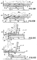
- the conversion of the bed 10 of this invention from the bed position to the chair position is shown schematically in Figs. 10A through 10D.
- the patient 22 is in a supine position atop the mattress 20 with the patient support platform 18 generally horizontal in the lowermost vertical position (Fig. 10A).
- the foot end portion 104 of the mattress 20 begins to deflate as the patient support platform 18 shifts longitudinally relative to the frame 14 toward the foot end of the bed 10 (Fig. 10B).
- the head panel 28 pivots upwardly and the interface between the thigh panel 32 and the foot panel 34 pivots upwardly.
- the patient 22 achieves a sitting position with his feet contacting the floor directly (Fig. 10C).
- the patient 22 is assisted in standing as the frame 14 elevates relative to the base 12 (Fig. 10D).
- the patient support platform 18 is lowered vertically to the lowermost position as shown in Fig. 8B. This can be accomplished by retraction of the fourth hydraulic cylinder 102 thereby collapsing the four bar linkage 96.
- the patient support platform 18 is translated longitudinally toward the foot end of the bed 10 by the retraction of the first hydraulic cylinder 70 (Fig.2).
- the rollers 62, 64 secured to the seat panel 30 roll within the C-shaped channel 68 secured to the frame 14.
- the third hydraulic cylinder 78 extends (Fig. 6) to thereby elevate and pivot upwardly the interface between the thigh panel 32 and foot panel 34 by about 5° as shown by the angle ⁇ (Fig. 4C).
- the second hydraulic cylinder 74 extends to pivot the head panel 28 upwardly.
- the foot end of the foot panel 34 pivots downwardly with the roller 88 extending from the post 86 acting as a fulcrum point enabling the block 92 and foot panel 34 secured thereto to pivot around the roller 88 as shown in Figs. 4A-C.
- the head end of the lateral sections 40, 40 of the foot panel 34 also pivot upwardly.
- the lateral sections 40, 40 do not drop below the frame 18 like the central section 38 because the lateral sections 40, 40 are supported by the arms 58, 58 of the U-shaped frame section 56 as shown in Fig. 7.
- the collapsing portion 46 of the foot panel 34 is biased by the spring 50 toward the outwardly extended bed configuration shown in Fig. 4A.
- the foot end of the pivoting portion 44 of the foot panel 34 pivots downwardly away from the frame 18 thereby extending the spring 50 and retracting the collapsing portion 46 within the pivoting portion 44 of the foot panel 34.
- the first link 82 likewise pivots downwardly thereby extending the spring 50, as the portion 46 slides into the recess 48 of foot panel 34, and moving the foot end of the pivoting portion 44 downwardly away from the frame 18 until the foot panel 34 achieves the generally vertical attitude shown in Fig. 4C of the chair configuration of the bed 10 of this invention.
- the first link 82 and the second link 84 are in a generally vertical attitude as is the foot panel 34 with the collapsing portion 46 telescoped into the pivoting portion 44.
- the portion 104 of mattress 20 is evacuated and a space is vacated at the foot end of the bed 10 permitting the patient 22 to egress from the bed 10.
- the retracted foot panel 34 is vertical thereby enabling the patient 22 to rest his feet directly on a floor surface underlying the bed 10 (Fig. 8A) and thereby avoiding confusion and inconvenience associated with the so-called "false floor” effect.
- the foot guards 26, 26 in the chair configuration, the foot panel 34 in the retracted vertical attitude, and the U-shaped frame section 56 at the foot end of the bed 10 cooperate to vacate a space enabling patient egress from the bed 10 to a standing upright position.
- a wheelchair, motorized scooter or motorized walker can be docked into the vacated space at the foot end of the bed 10 of this invention thereby providing convenient transfer of the patient 22 from the bed 10 to the ambulatory assisting device.
- the patient lift mechanism 94 is provided with this invention as shown in Figs. 8A-B and 9A-B.
- the fourth hydraulic cylinder 102 extends as shown in Fig. 9B to pivot the four bar linkage 96 and raise the frame 18 relative to the base 12 and urge the patient 22 from a sitting position to a standing or upright position (Fig. 9A).
Landscapes
- Health & Medical Sciences (AREA)
- Life Sciences & Earth Sciences (AREA)
- Animal Behavior & Ethology (AREA)
- General Health & Medical Sciences (AREA)
- Public Health (AREA)
- Veterinary Medicine (AREA)
- Nursing (AREA)
- Pain & Pain Management (AREA)
- Epidemiology (AREA)
- Physical Education & Sports Medicine (AREA)
- Rehabilitation Therapy (AREA)
- Invalid Beds And Related Equipment (AREA)
- Mattresses And Other Support Structures For Chairs And Beds (AREA)
- Air-Conditioning For Vehicles (AREA)
- Seats For Vehicles (AREA)
- Special Chairs (AREA)
- Massaging Devices (AREA)
Claims (35)
- Ein Krankenbett, das sich in einer im allgemeinen flachen Bettposition befindet und zu einer Sitzposition verstellbar ist und dem Patienten das Verlassen des Bettes über das Fußende desselben gestattet, welches aus einem Untergestell (12), einem auf dieses Untergestell (12) montierten Rahmen (14) und einer auf diesen Rahmen (14) montierten Patientenstützplattform (18) besteht sowie zusätzlich zumindest eine Kopfauflage (28) und eine Fußauflage (34) aufweist, wobei diese Kopfauflage (28) für eine Schwenkbewegung in eine aufrechte Position relativ zum Rahmen (14) montiert ist, wenn das Bett zu einer Sitzposition verstellt wird,
dadurch gekennzeichnet, daß die Fußauflage (34) ein schwenkbares Teilstück (44) und ein einklappbares Teilstück (46) aufweist, wobei das einklappbare Teilstück (46) relativ zum schwenkbaren Teilstück (44) ausgefahren bzw. in dieses zurückgezogen wird, wenn das schwenkbare Teilstück (44) nach oben bzw. nach unten geschwenkt wird. - Ein Bett nach Anspruch 1, dadurch gekennzeichnet, daß eine Verbindung (62, 64, 66, 70, 82, 84, 88) zwischen dem Rahmen (14) und der Plattform (18) angebracht ist, um die Plattform (18) in Längsrichtung relativ zu dem Rahmen (14) zu bewegen, das schwenkbare Teilstück (44) zu schwenken und das einklappbare Teilstück (46) einzuklappen, um die Plattform (18) zu bzw. zwischen der im allgemeinen ebenen Bettposition und der Sitzposition zu verstellen.
- Ein Bett nach Anspruch 2, dadurch gekennzeichnet, daß die Verbindung (62, 64, 66, 70, 82, 84, 88) jeweils an den Rahmen (14) und die Plattform (18) montierte Rollen (62, 64) für eine rollende Bewegung der Plattform (18) relativ zum Rahmen (14) aufweist.
- Ein Bett nach Anspruch 2, dadurch gekennzeichnet, daß die Verbindung (62, 64, 66, 70, 82, 84, 88) entweder an den Rahmen (14) oder die Plattform (18) montierte Rollen (62, 64) für eine rollende Bewegung der Plattform (18) relativ zum Rahmen (14) aufweist sowie eine Verbindung (62, 64, 66, 70, 82, 84, 88) zwischen dem Rahmen (14) und der Plattform (18) aufweist, um die Fußauflage (34) in eine vertikale Position zu bewegen, wenn die Plattform (18) in Längsrichtung zum Fußende des Bettes bewegt wird.
- Ein Bett nach Anspruch 2, dadurch gekennzeichnet, daß die Verbindung (62, 64, 66, 70, 82, 84, 88) entweder an den Rahmen (14) oder die Plattform (18) montierte Rollen (62, 64) für eine rollende Bewegung der Plattform (18) relativ zum Rahmen (14) aufweist, um die Fußauflage (34) in eine vertikale Position zu bewegen, wenn die Plattform (18) in Längsrichtung zum Fußende des Bettes hin bewegt wird.
- Ein Bett nach einem der Ansprüche 3 bis 5, dadurch gekennzeichnet, daß die Rollen (62, 64) an die Plattform (18) montiert sind, wobei das Bett weiterhin im allgemeinen C-förmige an dem Rahmen (14) befestigte Profile (68) aufweist und die Rollen (62, 64) bei Bewegung in Längsrichtung in den Profilen (68) laufen, und wobei das Bett eine an dem Rahmen (14) mit einem ersten Ende und an der Plattform (18) mit einem zweiten Ende befestigten Kolben-Zylinder-Einheit (78) umfaßt, um die Plattform (18) in Längsrichtung relativ zum Rahmen (14) zu bewegen.
- Ein Bett nach einem der Ansprüche 2 bis 6, dadurch gekennzeichnet, daß die Verbindung (62, 64, 66, 70, 82, 84, 88) mindestens ein Zwischenstück (82, 84) aufweist, welches das schwenkbare Teilstück der Fußauflage (34) schwenkbar mit dem Rahmen (14) verbindet, um die Fußauflage (34) in eine vertikale Position zu schwenken, wenn die Plattform (18) in Längsrichtung zum Fußende des Bettes hin bewegt wird.
- Ein Bett nach einem der vorhergehenden Ansprüche, dadurch gekennzeichnet, daß das einklappbare Teilstück (46) nach außen hin relativ zum schwenkbaren Teilstück (44) normalerweise elastisch vorgespannt ist, um sich zur Bettposition hin zu erstrecken.
- Ein Bett nach einem der vorhergehenden Ansprüche, dadurch gekennzeichnet, daß das einklappbare Teilstück (46) sich in das bzw. aus dem schwenkbaren Teilstück (44) der Fußauflage (34) schieben läßt.
- Ein Bett nach einem der vorhergehenden Ansprüche, dadurch gekennzeichnet, daß die Fußauflage (34) für eine Schwenkbewegung relativ zu dem Rahmen (14) montiert ist, um beim Verstellen des Bettes in eine Sitzposition in eine niedrigere Position zu schwenken, wobei das einklappbare Teilstück (46) der Fußauflage (34) bei deren Herunterschwenken so weit einklappbar ist, daß das einklappbare Teilstück (46) die Fußauflage (34) freigibt und so beim Verstellen des Bettes in eine Sitzposition störenden Kontakt zwischen der Fußauflage (34) und einem das Bett tragenden Boden verhindert, wenn der Rahmen (14) zur niedrigst möglichen Position abgesenkt worden ist, und es somit zu gestatten, daß der Rahmen (14) so zur niedrigst möglichen Position abgesenkt wird, daß die Füße eines Patienten direkt auf dem Fußboden zu stehen kommen und es dem Patienten somit zu gestatten, sich vom Fußende des Bettes fortzubewegen, wenn sich dieses in der Sitzposition befindet.
- Ein Bett nach einem der vorhergehenden Ansprüche, dadurch gekennzeichnet, daß die Fußauflage (34) über eine im Allgemeinen horizontale obere Position und eine im Allgemeinen vertikal nach unten verlaufende untere Position verfügt.
- Ein Bett nach einem der vorhergehenden Ansprüche, dadurch gekennzeichnet, daß die Fußauflage (34) zusätzlich ein nach unten schwenkbares Teilstück (44), seitliche Teilstücke (40) und ein verschiebbares Teilstück (48) aufweist, wobei das verschiebbare Teilstück (48) in einer durch das schwenkbare Teilstück (44) definierten Ebene weg von und hin zu dem schwenkbaren Teilstück (44) verschoben werden kann, wenn das schwenkbare Teilstück (44) entweder nach oben oder nach unten geschwenkt wird, wobei das schwenkbare sowie das verschiebbare Teilstück (44, 48) unter den Rahmen (14) gesenkt werden können und wobei die seitlichen Teilstücke (40) oberseitig von dem Rahmen (14) getragen werden.
- Ein Bett nach einem der vorhergehenden Ansprüche, dadurch gekennzeichnet, daß der Rahmen (14) ein U-förmiges Teilstück (56) am Fußende des Bettes aufweist, wobei das U-förmige Teilstück (56) über Arme verfügt und wobei das U-förmige Teilstück (56) über ein offenes Ende in Richtung zum Fußende des Bettes hin verfügt, wobei die Patientenstützplattform (18) die Fußauflage mit einem zentralen Teilstück (38) und seitlichen Teilstücken (40) aufweist, wobei sämtliche Teilstücke (38, 40) relativ zum Rahmen (14) schwenkbar montiert sind und das zentrale Teilstück (38) nach unten durch das U-förmige Teilstück (56) schwenkbar ist und die seitlichen Teilstücke (40) auf den Armen des U-förmigen Teilstücks (56) aufliegen.
- Ein Bett nach einem der Ansprüche 1 bis 12, dadurch gekennzeichnet, daß es mit einem U-förmigen Teilstück (56) als Teil des Rahmens (14) am Fußende des Bettes versehen ist, wobei das U-förmige Teilstück (56) ein Paar Arme sowie ein offenes Ende in Richtung zum Fußende des Bettes hin aufweist, und daß am äußeren Ende jedes Arms des U-förmigen Teilstücks (56) ein Trittbrett (56) schwenkbar montiert ist, wobei die Trittbretter so schwenkbar sind, daß sie im Allgemeinen kolinear zueinander verlaufen, wenn das Bett sich in der Bettposition befindet, so daß sie auf diese Weise als Fußschutzbügel (26) zusammenwirken, um dem Patienten Stabilität am Fußende des Bettes zu bieten, und wobei die Trittbretter geschwenkt werden können, um im Allgemeinen parallel zueinander an den jeweiligen Seitenschenkeln des Bettes zu verlaufen, wenn das Bett sich in der Sitzposition befindet, um vom Patienten für ein Wechseln zwischen der aufrecht sitzenden Position und der stehenden Position verwendet zu werden.
- Ein Bett nach einem der Ansprüche 1 bis 12, dadurch gekennzeichnet, daß der Rahmen (14) über ein U-förmiges Teilstück (56) am Fußende des Bettes verfügt, wobei das U-förmige Teilstück (56) ein offenes Ende in Richtung zum Fußende des Bettes hin aufweist, und das Fußende jedes der seitlichen Teilstücke (40) der Fußauflage (34) durch einen Arm des U-förmigen Teilstücks (56) getragen wird sowie das zentrale Teilstück (38) der Fußauflage (34) unter den Rahmen (14) zwischen den Armen des U-förmigen Teilstücks (56) absinkt, wenn es sich in der Sitzposition befindet.
- Ein Bett nach einem der Ansprüche 1 bis 12, dadurch gekennzeichnet, daß der Rahmen (14) über ein U-förmiges Teilstück (56) am Fußende des Bettes verfügt, wobei das U-förmige Teilstück (56) ein offenes Ende in Richtung zum Fußende des Bettes hin aufweist, und die Fußauflage (34) schwenkbar relativ zu dem Rahmen (14) montiert ist, um nach unten durch das U-förmige Teilstück (56) zu schwenken.
- Ein Bett nach einem der Ansprüche 13 bis 15, dadurch gekennzeichnet, daß die Fußauflage (34) schwenkbar relativ zu dem Rahmen (14) montiert ist, um nach unten durch das U-förmige Teilstück (56) zu schwenken.
- Ein Bett nach einem der Ansprüche 13 bis 17, dadurch gekennzeichnet, daß es mit einem Trittbrett versehen ist, das schwenkbar an das U-förmige Teilstück (56) am Fußende des Bettes jeweils an dessen Seitenschenkeln montiert ist, wobei die Trittbretter so schwenkbar sind, daß sie im Allgemeinen kolinear zueinander verlaufen, so daß sie auf diese Weise als Fußschutzbügel (26) zusammenwirken, um dem Patienten Stabilität am Fußende des Bettes zu bieten, und wobei die Trittbretter geschwenkt werden können, um im Allgemeinen parallel zueinander an den jeweiligen Seitenschenkeln des Bettes zu verlaufen, um von einem Patienten für ein Wechseln zwischen der aufrecht sitzenden Position und der stehenden Position verwendet zu werden.
- Ein Bett nach einem der vorhergehenden Ansprüche, dadurch gekennzeichnet, daß die Plattform (18) Gesäßund Oberschenkelauflagen (30, 32) aufweist, wobei die Kopf-, Gesäß-, Oberschenkel- und Fußauflagen (28, 30, 32, 34) aufeinander folgend gelenkig miteinander verbunden sind, die Gesäßauflage (30) in einer im Allgemeinen horizontalen Position verbleibt, und eine Verbindungsstelle zwischen den Gesäß- und Oberschenkelauflagen (30, 32) im vertikalen Sinne bewegbar ist.
- Ein Bett nach einem der Ansprüche 1 bis 18, dadurch gekennzeichnet, daß die Plattform (18) Gesäß- und Oberschenkelauflagen (30, 32) aufweist, wobei die Kopf-, Gesäß-, Oberschenkel- und Fußauflagen (28, 30, 32, 34) aufeinander folgend gelenkig miteinander verbunden sind, die Gesäßauflage (30) in einer im Allgemeinen horizontalen Position verbleibt, eine Verbindungsstelle zwischen den Gesäß- und Oberschenkelauflagen (30, 32) im horizontalen Sinne bewegbar ist, die Fußauflage (34) zusätzlich seitliche Teilstücke (40) aufweist, welche jeweils mit der Oberschenkelauflage schwenkbar verbunden sind, wobei das obere Ende jedes der seitlichen Teilstücke (40) mit der Oberschenkelauflage (32) nach oben bewegt wird und das untere Ende jedes der seitlichen Teilstücke (40) auf dem Rahmen (14) verbleiben, wenn das zentrale Teilstück (38) der Fußauflage unter den Rahmen (14) in die Sitzposition abgesenkt wird.
- Ein Bett nach entweder Anspruch 19 oder Anspruch 20, dadurch gekennzeichnet, daß es mit einer Verbindungsstelle zwischen den Fuß- und Oberschenkelauflagen (34, 32) versehen ist, wobei die Verbindungsstelle im vertikalen Sinne bewegbar ist, die Fußauflage (34) zusätzlich seitliche Teilstücke (40) aufweist, welche jeweils schwenkbar mit der Oberschenkelauflage (32) verbunden sind, wobei das obere Ende jedes der seitlichen Teilstücke mit der Oberschenkelauflage (32) nach oben bewegt wird und das untere Ende jedes der seitlichen Teilstücke (40) auf dem Rahmen (14) verbleibt, sobald das zentrale Teilstück (38) der Fußauflage (34) unter den Rahmen (14) in die Sitzposition abgesenkt wird.
- Ein Bett nach einem der Ansprüche 19 bis 21, dadurch gekennzeichnet, daß eine Oberschenkelauflage mit der Fußauflage (34) an einer Verbindungsstelle verbunden ist, und ein Kolben und Zylinder (78) an einem ersten Ende mit dem Rahmen (14) und an einem zweiten Ende mit der Plattform (18) verbunden sind, um die Verbindungsstelle zwischen den Oberschenkel- und Fußauflagen (32, 34) anzuheben bzw. abzusenken, wenn die Plattform (18) zu bzw. zwischen der Bettposition und. der Sitzposition verstellt wird.
- Ein Bett nach einem der vorhergehenden Ansprüche, dadurch gekennzeichnet, daß der Rahmen (14) zusätzlich eine schwenkbar mit der Fußauflage (34) an einer Verbindungsstelle verbundene Oberschenkelauflage (32) aufweist, und die Verbindungsstelle angehoben bzw. abgesenkt wird, wenn die Plattform (18) zu bzw. zwischen der Bettposition und der Sitzposition verstellt wird.
- Ein Bett nach einem der vorhergehenden Ansprüche, dadurch gekennzeichnet, daß der Rahmen (14) zusätzlich eine in einer im Allgemeinen horizontalen Position verbleibende Gesäßauflage (30) aufweist, wobei die Oberschenkelauflage (32) schwenkbar mit der Gesäßauflage (30) verbunden ist.
- Ein Bett nach einem der Ansprüche 1 bis 24, dadurch gekennzeichnet, daß der Rahmen (14) zusätzlich eine in einer im Allgemeinen horizontalen Position verbleibende Gesäßauflage (30) aufweist, wobei die Kopf- und Oberschenkelauflagen (28, 32) schwenkbar mit der Gesäßauflage (30) verbunden sind.
- Ein Bett nach einem der vorhergehenden Ansprüche, dadurch gekennzeichnet, daß die Kopfauflage (28) nach oben schwenkbar ist und die Fußauflage (34) ein nach unten schwenkbares Teilstück (44) aufweist und daß das Bett zusätzlich eine Matratze (20) aufweist, welche auf der Plattform (18) aufliegt und ein gesondert entleerbares Fußteil (104) aufweist, aus dem die Luft abgelassen werden kann, ohne ein weiteres Teil der Matratze (20) zu verändern.
- Ein Bett nach einem der Ansprüche 1 bis 25, dadurch gekennzeichnet, daß es mit einer Matratze (20) versehen ist, welche auf der Patientenstützplattform (18) aufliegt und ein gesondert entleerbares Fußteil (104) aufweist, aus dem die Luft abgelassen werden kann, ohne ein weiteres Teil der Matratze (20) zu verändern, wodurch das Bett die Fortgeh-Position einnimmt, sobald die Fußauflage in die untere Position geschwenkt ist sowie die Luft aus dem entleerbaren Teil (104) der Matratze entwichen ist.
- Ein Bett nach entweder Anspruch 26 oder 27, dadurch gekennzeichnet, daß das Bett die Sitzposition einnimmt durch Schwenken der Kopfauflage (28) nach oben, Schwenken der Fußauflage (34) nach unten und Entleeren des entleerbaren Teils (104) der Matratze (20).
- Ein Bett nach einem der vorhergehenden Ansprüche, dadurch gekennzeichnet, daß ein Block (92) an dem einklappbaren Teilstück (46) der Fußauflage (34) befestigt ist sowie eine Rolle (62, 64) an den Rahmen (14) montiert ist, welche mit dem Block (92) zusammenwirkt, um das einklappbare Teilstück (46) der Fußauflage (34) zurückzuziehen, sobald die Fußauflage (34) in die Sitzposition geschwenkt wird.
- Ein Bett nach einem der vorhergehenden Ansprüche, dadurch gekennzeichnet, daß es sich bei dem Bett um ein Krankenhausbett handelt.
- Ein Verfahren zum des Fortbewegens eines Patienten vom Fußende eines zu einem Sitz verstellten Bettes, wobei es sich um ein Bett mit einem Untergestell (12), einem auf das Untergestell (12) montierten Rahmen (14), einer auf den Rahmen (14) montierten Patientenstützplattform (18) handelt und weiterhin zumindest Kopf- und Fußauflagen (28, 34), wobei die Kopfauflage (28) für eine Schwenkbewegung in eine aufrechte Position relativ zum Rahmen (14) montiert ist, wenn das Bett zu einer Sitzposition verstellt wird, dadurch gekennzeichnet, daß die Fußauflage (34) ein schwenkbares Teilstück (44) und ein einklappbares Teilstück (46) aufweist, wobei das einklappbare Teilstück (46) von dem schwenkbaren Teilstück (44) ausgefahren bzw. in dieses zurückgezogen wird, je nachdem, ob das schwenkbare Teilstück (44) nach oben bzw. nach unten geschwenkt wird.
- Eine Verfahren nach Anspruch 31, dadurch gekennzeichnet, daß der zugehörige Rahmen (14) für vertikale Bewegung relativ zu dem Untergestell (12) montiert ist.
- Ein Verfahren nach Anspruch 31 oder Anspruch 32, dadurch gekennzeichnet, daß die Kopfauflage (28) nach oben geschwenkt wird und die zugehörige Fußauflage (34) nach unten geschwenkt wird.
- Ein Verfahren nach Anspruch 31 oder 32, dadurch gekennzeichnet, daß das Bett zusätzlich je einen auf jeder Seite des Rahmens (14) nahe dessen Fußende montierten Schutzbügel (24, 26) aufweist.
- Ein Verfahren nach einem der Ansprüche 31 bis 34, dadurch gekennzeichnet, daß der Rahmen (14) zur niedrigst möglichen Position abgesenkt wird, die Kopfauflage (28) geschwenkt wird, die Fußauflage (34) nach unten geschwenkt und umgeklappt wird, um ein Teilstück der Fußauflage (34) freizugeben und so störenden Kontakt zwischen der Fußauflage (34) und dem Fußboden zu verhindern, wobei die Füße des Patienten direkt auf dem Fußboden positioniert werden, die Hände des Patienten so positioniert werden, daß sie die Schutzbügel (24, 26) umfassen, um den Patienten beim Erheben aus der sitzenden Position zu unterstützen, und wobei der Bettrahmen (14) nach oben bewegt wird, um den Patienten dabei zu unterstützen, sich bis zu einer stehenden Position zu erheben und sich vom Bett fortzubewegen.
Applications Claiming Priority (3)
| Application Number | Priority Date | Filing Date | Title |
|---|---|---|---|
| US186657 | 1994-01-25 | ||
| US08/186,657 US5479666A (en) | 1994-01-25 | 1994-01-25 | Foot egress chair bed |
| PCT/US1995/000980 WO1995019755A1 (en) | 1994-01-25 | 1995-01-25 | Foot egress chair bed |
Publications (2)
| Publication Number | Publication Date |
|---|---|
| EP0744934A1 EP0744934A1 (de) | 1996-12-04 |
| EP0744934B1 true EP0744934B1 (de) | 2002-12-04 |
Family
ID=22685797
Family Applications (1)
| Application Number | Title | Priority Date | Filing Date |
|---|---|---|---|
| EP95911577A Expired - Lifetime EP0744934B1 (de) | 1994-01-25 | 1995-01-25 | Fussausgang für sitzbett |
Country Status (10)
| Country | Link |
|---|---|
| US (1) | US5479666A (de) |
| EP (1) | EP0744934B1 (de) |
| JP (1) | JP4231549B2 (de) |
| AT (1) | ATE228811T1 (de) |
| AU (1) | AU1909095A (de) |
| CA (1) | CA2182019C (de) |
| DE (1) | DE69529058T2 (de) |
| DK (1) | DK0744934T3 (de) |
| ES (1) | ES2185696T3 (de) |
| WO (1) | WO1995019755A1 (de) |
Cited By (8)
| Publication number | Priority date | Publication date | Assignee | Title |
|---|---|---|---|---|
| EP2181684A1 (de) | 2008-11-03 | 2010-05-05 | Völker AG | Bett, insbesondere Kranken- oder Pflegebett |
| EP2589363A1 (de) | 2011-11-04 | 2013-05-08 | Völker AG | Bett, insbesondere Kranken- oder Pflegebett |
| EP2589362A1 (de) | 2011-11-04 | 2013-05-08 | Völker AG | Bett, insbesondere Kranken- oder Pflegebett |
| EP2591760A1 (de) | 2011-11-08 | 2013-05-15 | Völker AG | Bett, insbesondere Kranken- oder Pflegebett |
| EP2591759A1 (de) | 2011-11-08 | 2013-05-15 | Völker AG | Bett, insbesondere Kranken- oder Pflegebett |
| US9486373B2 (en) | 2013-03-14 | 2016-11-08 | Stryker Corporation | Reconfigurable patient support |
| US9510981B2 (en) | 2013-03-14 | 2016-12-06 | Stryker Corporation | Reconfigurable transport apparatus |
| EP4197512A1 (de) * | 2021-12-14 | 2023-06-21 | Wissner-Bosserhoff GmbH | Bett, insbesondere medizinisches bett, mit einem untergestell und einem daran über verbinder befestigten obergestell |
Families Citing this family (137)
| Publication number | Priority date | Publication date | Assignee | Title |
|---|---|---|---|---|
| US6374436B1 (en) * | 1994-01-25 | 2002-04-23 | Hill-Rom Services, Inc. | Hospital bed |
| US5337845A (en) * | 1990-05-16 | 1994-08-16 | Hill-Rom Company, Inc. | Ventilator, care cart and motorized transport each capable of nesting within and docking with a hospital bed base |
| US5680661A (en) | 1990-05-16 | 1997-10-28 | Hill-Rom, Inc. | Hospital bed with user care apparatus |
| US5577279A (en) * | 1990-05-16 | 1996-11-26 | Hill-Rom Company, Inc. | Hospital bed |
| US5715548A (en) * | 1994-01-25 | 1998-02-10 | Hill-Rom, Inc. | Chair bed |
| US6212714B1 (en) | 1995-01-03 | 2001-04-10 | Hill-Rom, Inc. | Hospital bed and mattress having a retracting foot section |
| USRE43155E1 (en) * | 1995-01-03 | 2012-02-07 | Hill-Rom Services, Inc. | Hospital bed and mattress having a retractable foot section |
| US6499167B1 (en) | 1995-08-04 | 2002-12-31 | Hill-Rom Services, Inc. | Mattress section support |
| US6584628B1 (en) | 1995-08-04 | 2003-07-01 | Hill-Rom Services, Inc. | Hospital bed having a rotational therapy device |
| US7017208B2 (en) | 1995-08-04 | 2006-03-28 | Hill-Rom Services, Inc. | Hospital bed |
| US5732423A (en) * | 1995-08-04 | 1998-03-31 | Hill-Rom, Inc. | Bed side rails |
| US5692256A (en) * | 1995-08-04 | 1997-12-02 | Hill-Rom, Inc. | Mattress for a hospital bed |
| US5682631A (en) * | 1995-08-04 | 1997-11-04 | Hill-Rom, Inc. | Bed having a reduced-shear pivot and step deck combination |
| US5630238A (en) * | 1995-08-04 | 1997-05-20 | Hill-Rom, Inc. | Bed with a plurality of air therapy devices, having control modules and an electrical communication network |
| US5774914A (en) * | 1996-01-05 | 1998-07-07 | Stryker Corporation | Maternity bed |
| US6089593A (en) * | 1997-02-10 | 2000-07-18 | Hill-Rom, Inc. | Ambulatory care chair |
| US5894966A (en) * | 1997-06-26 | 1999-04-20 | Hill-Rom, Inc. | Bariatric bed |
| US6694557B1 (en) | 1997-06-26 | 2004-02-24 | Hill-Rom Services, Inc. | Bariatric bed |
| US6739006B2 (en) | 1997-11-07 | 2004-05-25 | Hill-Rom Services, Inc. | Head section support for a surgical table apparatus |
| US6754923B2 (en) | 1997-11-07 | 2004-06-29 | Hill-Rom Services, Inc. | Leg section support for a surgical table |
| AU3493499A (en) * | 1998-04-14 | 1999-11-01 | Scott M. Corbin | Communication and bed function control apparatus |
| US6282738B1 (en) | 1998-08-07 | 2001-09-04 | Hill-Rom, Inc. | Ob/Gyn stretcher |
| US6427264B1 (en) | 1999-03-19 | 2002-08-06 | Hill-Rom Services, Inc. | Gap filler for bed |
| US6757924B2 (en) | 1999-08-23 | 2004-07-06 | Hill-Rom Services, Inc. | Bed having a removable foot section |
| WO2001028483A1 (en) * | 1999-10-15 | 2001-04-26 | Hill-Rom, Inc. | Siderail pad for hospital bed |
| AU2744701A (en) * | 1999-12-29 | 2001-07-09 | Hill-Rom Services, Inc. | Hospital bed |
| EP1286640B1 (de) * | 2000-06-02 | 2009-08-05 | Hill-Rom Services, Inc. | Fussstütze für patientenliege |
| IL138968A0 (en) * | 2000-10-12 | 2001-11-25 | Hollandia Internat | Articulated bed frame |
| US7100222B2 (en) * | 2001-08-22 | 2006-09-05 | Hill-Rom Services, Inc. | Apparatus and method for mounting hospital bed accessories |
| ATE413856T1 (de) | 2001-08-22 | 2008-11-15 | Hill Rom Services Inc | Gerät und verfahren zum schliessen von lücken in krankenhausbetten |
| US7530127B2 (en) | 2002-05-24 | 2009-05-12 | Dan-Foam Aps | Pillow and method of manufacturing a pillow |
| CA2487022C (en) | 2002-05-24 | 2009-12-22 | Tempur World, Inc. | Comfort pillow |
| USD479070S1 (en) | 2002-09-06 | 2003-09-02 | Hill-Rom Services, Inc. | Bed siderail |
| EP2181685B1 (de) * | 2002-09-06 | 2014-05-14 | Hill-Rom Services, Inc. | Krankenbett mit einer geregelten aufblasbaren Auflage |
| US7073220B2 (en) | 2002-09-06 | 2006-07-11 | Hill-Rom Services, Inc. | Bed siderail having a latch |
| US6820293B2 (en) | 2002-09-26 | 2004-11-23 | Hill-Rom Services, Inc. | Bed siderail pad apparatus |
| WO2004060257A2 (en) * | 2002-12-26 | 2004-07-22 | Gendron, Inc. | Bariatric patient management system |
| EP1729612A1 (de) | 2004-03-12 | 2006-12-13 | Hill-Rom Services, Inc. | Höhenverstellbares seitengitter für ein bett |
| US20060085914A1 (en) * | 2004-06-14 | 2006-04-27 | Steve Peterson | Adjustable bed for bariatric patients |
| US20060016016A1 (en) * | 2004-07-26 | 2006-01-26 | Hornbach David W | Modular bed system |
| US7886380B2 (en) | 2004-07-28 | 2011-02-15 | Hill-Rom Services, Inc. | Hospital bed |
| US7543583B2 (en) * | 2004-07-28 | 2009-06-09 | Hill-Rom Services, Inc. | Forced air vent in siderail |
| EP2198820B1 (de) * | 2004-07-30 | 2013-06-26 | Hill-Rom Services, Inc. | Patientenliege mit motorisierter einstellbarer Breite |
| JP2008509790A (ja) | 2004-08-16 | 2008-04-03 | ヒル−ロム サービシーズ,インコーポレイティド | 椅子 |
| AU2005277503A1 (en) * | 2004-08-16 | 2006-03-02 | Hill-Rom Services, Inc. | Home care equipment system |
| US20060056616A1 (en) * | 2004-09-10 | 2006-03-16 | Heimbrock Richard H | Hospital telephone and device controller |
| US7757318B2 (en) * | 2004-09-13 | 2010-07-20 | Kreg Therapeutics, Inc. | Mattress for a hospital bed |
| US7676862B2 (en) * | 2004-09-13 | 2010-03-16 | Kreg Medical, Inc. | Siderail for hospital bed |
| US7779494B2 (en) * | 2004-09-13 | 2010-08-24 | Kreg Therapeutics, Inc. | Bed having fixed length foot deck |
| US7743441B2 (en) * | 2004-09-13 | 2010-06-29 | Kreg Therapeutics, Inc. | Expandable width bed |
| US7536734B2 (en) | 2005-01-31 | 2009-05-26 | Hill-Rom Services, Inc. | Birthing support apparatus |
| US7788748B2 (en) * | 2005-04-06 | 2010-09-07 | Piedmont Global Solutions, Inc. | Hospital beds with a rotating sleep surface that can translate into a chair configuration |
| US7469437B2 (en) | 2005-06-24 | 2008-12-30 | Tempur-Pedic Management, Inc. | Reticulated material body support and method |
| US7536739B2 (en) * | 2005-08-10 | 2009-05-26 | Kreg Medical, Inc. | Therapeutic mattress |
| US7757317B2 (en) | 2005-11-17 | 2010-07-20 | Hill-Rom Services, Inc. | Stowing birthing bed foot section |
| US8104122B2 (en) * | 2005-12-19 | 2012-01-31 | Hill-Rom Services, Inc. | Patient support having an extendable foot section |
| EP2556811A1 (de) | 2006-02-08 | 2013-02-13 | Hill-Rom Services, Inc. | Endplatte für Patientenauflagevorrichtung |
| EP3032029B1 (de) | 2006-05-09 | 2017-12-06 | Hill-Rom Services, Inc. | Pulmonarmatratze |
| US20090091175A1 (en) * | 2007-10-09 | 2009-04-09 | Continuum Footspas, Llc | Spa device with leg rests and calf supports |
| US8296874B2 (en) * | 2007-10-23 | 2012-10-30 | Continuum Footspas, Llc | Basin for a foot spa |
| US7930778B2 (en) | 2007-12-07 | 2011-04-26 | Hill-Rom Services, Inc. | Pinch-preventing unit for bed guardrail |
| US8296884B2 (en) * | 2008-03-13 | 2012-10-30 | Hill-Rom Services, Inc. | Siderail gap filler |
| US8239986B2 (en) | 2008-03-13 | 2012-08-14 | Hill-Rom Services, Inc. | Siderail assembly for a patient-support apparatus |
| US20110156465A1 (en) * | 2008-05-30 | 2011-06-30 | White William L | Dissembled chair with deployable stirrups |
| WO2009158018A1 (en) | 2008-06-27 | 2009-12-30 | Kreg Medical, Inc. | Bed with modified foot deck |
| US8495774B2 (en) * | 2008-09-12 | 2013-07-30 | Piedmont 361, Llc | Hospital chair beds with articulating foot sections |
| DE102008051603A1 (de) * | 2008-10-14 | 2010-04-15 | Lufthansa Technik Ag | Sitz für ein Verkehrsmittel |
| US8341776B2 (en) | 2009-07-15 | 2013-01-01 | Continuum Footspas, Llc | Adjustable leg rest assembly |
| DE102010037113A1 (de) | 2009-10-12 | 2011-08-25 | Joh. Stiegelmeyer GmbH & Co. KG, 32051 | Bett mit Aussteigehilfe |
| US8858409B2 (en) | 2009-12-14 | 2014-10-14 | Hill-Rom Services, Inc. | Patient support apparatuses with exercise functionalities |
| US9265677B2 (en) | 2009-12-23 | 2016-02-23 | Piedmont 361, Llc | Hospital chair beds with stowable stand-assist supports |
| US10426677B2 (en) | 2010-01-20 | 2019-10-01 | The Uab Research Foundation | Reclining transport chairs |
| CA2825296C (en) | 2010-01-20 | 2019-08-13 | The Uab Research Foundation | Transport chairs |
| US8793824B2 (en) | 2010-03-17 | 2014-08-05 | Kreg Medical, Inc. | Tilt bed |
| KR101211236B1 (ko) * | 2010-06-23 | 2012-12-11 | 정원하 | 물리치료기용 골반지지구조 |
| US8646131B2 (en) | 2010-07-30 | 2014-02-11 | Hill-Rom Services, Inc. | Variable height siderail |
| US8397327B2 (en) | 2010-08-31 | 2013-03-19 | Span-America Medical Systems, Inc. | Bed insert |
| JP5524801B2 (ja) * | 2010-10-18 | 2014-06-18 | パラマウントベッド株式会社 | ベッド装置及び足下げ機構 |
| US8844075B2 (en) | 2010-10-22 | 2014-09-30 | Hill-Rom Services, Inc. | Footboard with partial mattress integration |
| US8381337B2 (en) | 2010-10-29 | 2013-02-26 | Hill-Rom Services, Inc. | Egress assist footboard |
| US20120124746A1 (en) * | 2010-11-22 | 2012-05-24 | Kirill Andrienko | Patient support apparatus with egress units |
| US8341779B2 (en) | 2010-12-06 | 2013-01-01 | Hill-Rom Services, Inc. | Retractable foot caster supports |
| US8336134B2 (en) | 2011-02-03 | 2012-12-25 | Hill-Rom Services, Inc. | Bed with mobile lift docking |
| US20120198626A1 (en) * | 2011-02-03 | 2012-08-09 | Richards Sandy M | Patient support apparatus with multipurpose foot deck section |
| US8474076B2 (en) | 2011-02-04 | 2013-07-02 | Hill-Rom Services, Inc. | Adjustable foot section for a patient support apparatus |
| US8341778B2 (en) | 2011-02-07 | 2013-01-01 | Hill-Rom Services, Inc. | Bed gap filler and footboard pad |
| US20120246830A1 (en) * | 2011-03-31 | 2012-10-04 | Hornbach David W | Footboard egress design |
| US9833369B2 (en) | 2012-06-21 | 2017-12-05 | Hill-Rom Services, Inc. | Patient support systems and methods of use |
| JP6017686B2 (ja) | 2012-06-21 | 2016-11-02 | ヒル−ロム サービシズ,インコーポレイテッド | 患者保持システムおよび使用方法 |
| US9228885B2 (en) | 2012-06-21 | 2016-01-05 | Hill-Rom Services, Inc. | Patient support systems and methods of use |
| USD677919S1 (en) * | 2012-08-28 | 2013-03-19 | William E. Voyce, IV | Chair |
| KR101326767B1 (ko) * | 2012-08-31 | 2013-11-08 | 박종호 | 이동 보조기 |
| US9173796B2 (en) | 2013-02-05 | 2015-11-03 | Hill-Rom Services, Inc. | Bed with a powered width expansion wing with manual release |
| USD869659S1 (en) | 2013-03-15 | 2019-12-10 | Stryker Corporation | Emergency cot side rail |
| USD710509S1 (en) | 2013-09-23 | 2014-08-05 | Hill-Rom Services Pte. Ltd. | Head rail for a patient bed |
| USD710510S1 (en) | 2013-09-23 | 2014-08-05 | Hill-Rom Services Pte. Ltd. | Foot rail for a patient bed |
| USD710507S1 (en) | 2013-09-23 | 2014-08-05 | Hill-Rom Services Pte. Ltd. | Patient bed |
| CZ305564B6 (cs) * | 2013-11-07 | 2015-12-09 | MORAVSKĂť VĂťZKUM, s.r.o. | Robotické mobilní modifikovatelné lůžko |
| EP2873400B1 (de) | 2013-11-18 | 2018-01-31 | Völker GmbH | Personentragevorrichtung |
| US9038218B1 (en) | 2014-01-15 | 2015-05-26 | Hill-Rom Services, Inc. | Person support apparatuses with selectively coupled foot sections |
| US9132051B2 (en) * | 2014-01-15 | 2015-09-15 | Hill-Rom Services, Inc. | Person support apparatuses with exercise functionalities |
| US9463126B2 (en) | 2014-03-11 | 2016-10-11 | Hill-Rom Services, Inc. | Caregiver universal remote cart for patient bed control |
| US10179077B2 (en) | 2014-04-18 | 2019-01-15 | Kreg Medical, Inc. | Patient support with stand-up and sit features |
| US10363182B2 (en) | 2014-07-14 | 2019-07-30 | Hill-Rom Services, Inc. | Patient control arm with phone dock and head of bed lockout |
| USD770824S1 (en) | 2014-08-12 | 2016-11-08 | Hill-Rom Services, Inc. | Barrier for a hospital bed |
| USD769042S1 (en) | 2014-08-12 | 2016-10-18 | Hill-Rom Services, Inc. | Head end siderail |
| USD768422S1 (en) | 2014-08-12 | 2016-10-11 | Hill-Rom Services, Inc. | Foot end siderail |
| US10188567B2 (en) | 2014-10-30 | 2019-01-29 | Byron Wade Wurdeman | Hospital chair beds with extendable/retractable foot sections |
| KR101494354B1 (ko) * | 2014-11-03 | 2015-02-23 | 임윤택 | 좌변기로 변환가능한 환자용 베드 체어 |
| USD770829S1 (en) | 2015-01-29 | 2016-11-08 | Hill-Rom Services, Inc. | Head rail for patient bed |
| USD771259S1 (en) | 2015-01-29 | 2016-11-08 | Hill-Rom Services, Inc. | Foot rail for patient bed |
| US10426680B2 (en) | 2015-07-31 | 2019-10-01 | Hill-Rom Services, Inc. | Air bladder control of mattress/frame width expansion |
| CN105919744B (zh) * | 2016-05-24 | 2018-02-06 | 卢红 | 儿科护理床 |
| USD804882S1 (en) | 2016-05-28 | 2017-12-12 | Hill-Rom Services, Inc. | Headrail |
| USD804883S1 (en) | 2016-05-28 | 2017-12-12 | Hill-Rom Services, Inc. | Footrail |
| FR3052074B1 (fr) * | 2016-06-03 | 2022-03-04 | Off Matrix Holdings Sa | Procede de relaxation et fauteuil ambulatoire permettant la mise en oeuvre dudit procede |
| US10154930B2 (en) | 2016-08-01 | 2018-12-18 | Stryker Corporation | EMS backboard |
| US11020293B2 (en) | 2016-08-01 | 2021-06-01 | Stryker Corporation | Multi-function person handling equipment |
| US11147726B2 (en) | 2016-08-01 | 2021-10-19 | Stryker Corporation | Person support apparatus system |
| US10857052B1 (en) * | 2016-08-31 | 2020-12-08 | Pivotal Health Solutions, Inc. | Treatment table for therapeutic treatment, physical rehabilitation and training and method of use |
| US11304864B2 (en) * | 2016-09-02 | 2022-04-19 | Stryker Corporation | Patient support systems with a chair configuration and a stowable foot section |
| JP2019030580A (ja) * | 2017-08-09 | 2019-02-28 | エムアイ技研株式会社 | 車椅子 |
| US11266554B2 (en) | 2017-09-08 | 2022-03-08 | Kreg Medical, Inc. | Bed base frame |
| US11116680B2 (en) | 2017-09-19 | 2021-09-14 | Stryker Corporation | Patient support apparatus for controlling patient ingress and egress |
| US11052005B2 (en) | 2017-09-19 | 2021-07-06 | Stryker Corporation | Patient support apparatus with handles for patient ambulation |
| US11160705B2 (en) | 2017-10-20 | 2021-11-02 | Stryker Corporation | Adjustable patient support apparatus for assisted egress and ingress |
| EP3607924A1 (de) | 2018-08-07 | 2020-02-12 | Invacare International GmbH | Bett mit einem betätigbaren matratze-stützplattform und verfahren zum betätigen eines solchen betts |
| CN109009719B (zh) * | 2018-08-22 | 2024-02-06 | 中国人民解放军陆军军医大学第二附属医院 | 一种便于病人躺上核磁共振床的中转安全椅 |
| EP3643283A1 (de) | 2018-10-22 | 2020-04-29 | Hill-Rom Services, Inc. | System zum einstellen der konfiguration einer patientenliegevorrichtung |
| US11304861B2 (en) | 2019-08-02 | 2022-04-19 | Stryker Corporation | Patient transport apparatus with movable end handle system |
| JP6957572B2 (ja) | 2019-09-19 | 2021-11-02 | フランスベッド株式会社 | ベッド装置 |
| US11963918B2 (en) | 2020-04-20 | 2024-04-23 | Hill-Rom Services, Inc. | Patient bed having active motion exercise |
| CN111642932B (zh) * | 2020-05-20 | 2024-08-16 | 郏选德 | 一种可调节的床护栏支撑结构 |
| CN112155892B (zh) * | 2020-09-29 | 2023-03-24 | 安徽力威精工机械有限公司 | 智能多功能照护管理系统 |
| CN112515875B (zh) * | 2020-11-30 | 2021-12-28 | 张颜 | 一种智能医疗护理装置及其使用方法 |
| CN113332071A (zh) * | 2021-06-04 | 2021-09-03 | 广东省聚怡健康产业科技有限公司 | 一种可分拆为轮椅的组合式旋转型病床 |
| CA3234059A1 (en) | 2021-10-14 | 2023-04-20 | Leslie Dale Foster | Hospital bed with foot egress |
Family Cites Families (24)
| Publication number | Priority date | Publication date | Assignee | Title |
|---|---|---|---|---|
| US1398203A (en) * | 1921-02-19 | 1921-11-22 | Henry A Schmidt | Convertible bed-spring |
| DE595097C (de) * | 1932-09-18 | 1934-04-04 | I G Farbenindustrie Akt Ges | Verfahren zur Herstellung von Anthrapyrimidinen |
| US2308592A (en) * | 1940-03-13 | 1943-01-19 | Robert R Freund | Hospitalization and posture bed |
| DE716981C (de) * | 1940-04-13 | 1942-02-03 | Leo Mohren | Krankenbett mit einer als Tuer ausgebildeten Fusswand |
| US3038174A (en) * | 1960-06-23 | 1962-06-12 | Brown Donovan | Paraplegic hospital chair |
| US3032059A (en) * | 1960-09-28 | 1962-05-01 | Dura Corp | Fluid flow control device |
| US3210779A (en) * | 1961-09-11 | 1965-10-12 | Ted E Herbold | Multiple position combination chair-bed |
| US3281141A (en) * | 1963-01-15 | 1966-10-25 | American Sterilizer Co | Surgical table |
| US3220022A (en) * | 1963-12-23 | 1965-11-30 | Nelson Ted | Hospital bed sliding foot section |
| US3593350A (en) * | 1969-03-13 | 1971-07-20 | Dominion Metalware Ind Ltd The | Retractable bed |
| CH595097A5 (en) * | 1976-10-11 | 1978-01-31 | Walter Blaser | Invalid chair with swinging back and leg rest |
| US4139917A (en) * | 1977-10-17 | 1979-02-20 | Loel Fenwick | Labor, delivery and patient care bed |
| US4183109A (en) * | 1978-04-21 | 1980-01-15 | Howell William H | Sectional bed |
| US4227269A (en) * | 1978-09-01 | 1980-10-14 | Burke, Inc. | Adjustable bed |
| GB2147201B (en) * | 1983-10-01 | 1987-03-25 | Hoskins Ltd | Maternity bed |
| US4787104A (en) * | 1984-10-18 | 1988-11-29 | Grantham Frederick W | Convertible hospital bed |
| US4862529A (en) * | 1988-07-13 | 1989-09-05 | Hill-Rom Company, Inc. | Hospital bed convertible to chair |
| US4894876A (en) * | 1988-07-15 | 1990-01-23 | Hill-Rom Company, Inc. | Multipurpose maternity care bed |
| US5077843A (en) * | 1990-07-28 | 1992-01-07 | Hill-Rom Company, Inc. | Hospital bed and assemblies of hospital care apparatus |
| US4987620A (en) * | 1989-10-03 | 1991-01-29 | Benjamin Sharon | Combined bed and wheelchair |
| US5072463A (en) * | 1991-04-11 | 1991-12-17 | Willis William J | EZ access bed |
| US5157800A (en) * | 1991-04-15 | 1992-10-27 | Hill-Rom Company, Inc. | Foot section for birthing bed |
| US5095561A (en) * | 1991-05-09 | 1992-03-17 | Green Kenneth J | Invalid bed |
| US5279018A (en) * | 1992-01-10 | 1994-01-18 | Ryobi Motor Products Corp. | Quick connect rotary bearing for a vacuum cleaner |
-
1994
- 1994-01-25 US US08/186,657 patent/US5479666A/en not_active Expired - Lifetime
-
1995
- 1995-01-25 WO PCT/US1995/000980 patent/WO1995019755A1/en not_active Ceased
- 1995-01-25 CA CA002182019A patent/CA2182019C/en not_active Expired - Fee Related
- 1995-01-25 ES ES95911577T patent/ES2185696T3/es not_active Expired - Lifetime
- 1995-01-25 AU AU19090/95A patent/AU1909095A/en not_active Abandoned
- 1995-01-25 DK DK95911577T patent/DK0744934T3/da active
- 1995-01-25 AT AT95911577T patent/ATE228811T1/de not_active IP Right Cessation
- 1995-01-25 EP EP95911577A patent/EP0744934B1/de not_active Expired - Lifetime
- 1995-01-25 JP JP51974095A patent/JP4231549B2/ja not_active Expired - Fee Related
- 1995-01-25 DE DE69529058T patent/DE69529058T2/de not_active Expired - Lifetime
Cited By (13)
| Publication number | Priority date | Publication date | Assignee | Title |
|---|---|---|---|---|
| EP2181684A1 (de) | 2008-11-03 | 2010-05-05 | Völker AG | Bett, insbesondere Kranken- oder Pflegebett |
| CN102196794B (zh) * | 2008-11-03 | 2013-08-21 | 沃尔克股份有限公司 | 特别作为病床或护理床的床 |
| EP2589363A1 (de) | 2011-11-04 | 2013-05-08 | Völker AG | Bett, insbesondere Kranken- oder Pflegebett |
| EP2589362A1 (de) | 2011-11-04 | 2013-05-08 | Völker AG | Bett, insbesondere Kranken- oder Pflegebett |
| EP2591760A1 (de) | 2011-11-08 | 2013-05-15 | Völker AG | Bett, insbesondere Kranken- oder Pflegebett |
| EP2591759A1 (de) | 2011-11-08 | 2013-05-15 | Völker AG | Bett, insbesondere Kranken- oder Pflegebett |
| US9486373B2 (en) | 2013-03-14 | 2016-11-08 | Stryker Corporation | Reconfigurable patient support |
| US9510981B2 (en) | 2013-03-14 | 2016-12-06 | Stryker Corporation | Reconfigurable transport apparatus |
| US9925098B2 (en) | 2013-03-14 | 2018-03-27 | Stryker Corporation | Reconfigurable transport apparatus |
| US10406043B2 (en) | 2013-03-14 | 2019-09-10 | Stryker Corporation | Transport apparatus |
| US11071661B2 (en) | 2013-03-14 | 2021-07-27 | Stryker Corporation | Transport apparatus |
| US11737933B2 (en) | 2013-03-14 | 2023-08-29 | Stryker Corporation | Transport apparatus |
| EP4197512A1 (de) * | 2021-12-14 | 2023-06-21 | Wissner-Bosserhoff GmbH | Bett, insbesondere medizinisches bett, mit einem untergestell und einem daran über verbinder befestigten obergestell |
Also Published As
| Publication number | Publication date |
|---|---|
| JP4231549B2 (ja) | 2009-03-04 |
| AU1909095A (en) | 1995-08-08 |
| CA2182019A1 (en) | 1995-07-27 |
| ATE228811T1 (de) | 2002-12-15 |
| CA2182019C (en) | 2004-11-30 |
| DE69529058D1 (de) | 2003-01-16 |
| WO1995019755A1 (en) | 1995-07-27 |
| EP0744934A1 (de) | 1996-12-04 |
| US5479666A (en) | 1996-01-02 |
| ES2185696T3 (es) | 2003-05-01 |
| DK0744934T3 (da) | 2003-01-06 |
| DE69529058T2 (de) | 2003-04-24 |
| JPH09508041A (ja) | 1997-08-19 |
Similar Documents
| Publication | Publication Date | Title |
|---|---|---|
| EP0744934B1 (de) | Fussausgang für sitzbett | |
| EP0746298B1 (de) | Bett-stuhl mit ausstieg am fussende | |
| US6374436B1 (en) | Hospital bed | |
| US6112345A (en) | Hospital bed | |
| US7458119B2 (en) | Bed having a chair egress position | |
| AU704795B2 (en) | Table/chair egress device | |
| CA1308866C (en) | Hospital bed convertible to chair | |
| US5680661A (en) | Hospital bed with user care apparatus | |
| US20060085914A1 (en) | Adjustable bed for bariatric patients | |
| US6880186B2 (en) | Arrangement in a bed for a disabled person, and a bed provided with the said arrangement | |
| US10363187B2 (en) | Methods and apparatus for moving a patient from a reclining position to an upright sitting position | |
| US11759380B2 (en) | Hospital bed with foot egress | |
| CN107496105A (zh) | 一种便于上下床的护理床 | |
| US20020020018A1 (en) | Epidural patient support | |
| US6684419B1 (en) | Bedside lower extremity lifting apparatus | |
| WO2025038142A1 (en) | Hospital bed with foot egress | |
| CN216257922U (zh) | 一种卧床护理移动坐便装置 | |
| US11951054B2 (en) | Hospital bed with foot egress | |
| HK1014649B (en) | Foot egress chair bed | |
| CN111870442A (zh) | 一种用于转移失能人群的可折叠轮椅 | |
| CN113995596A (zh) | 一种卧床护理移动坐便装置 |
Legal Events
| Date | Code | Title | Description |
|---|---|---|---|
| PUAI | Public reference made under article 153(3) epc to a published international application that has entered the european phase |
Free format text: ORIGINAL CODE: 0009012 |
|
| 17P | Request for examination filed |
Effective date: 19960822 |
|
| AK | Designated contracting states |
Kind code of ref document: A1 Designated state(s): AT BE CH DE DK ES FR GB GR IE IT LI LU MC NL PT SE |
|
| 17Q | First examination report despatched |
Effective date: 19991216 |
|
| GRAG | Despatch of communication of intention to grant |
Free format text: ORIGINAL CODE: EPIDOS AGRA |
|
| GRAG | Despatch of communication of intention to grant |
Free format text: ORIGINAL CODE: EPIDOS AGRA |
|
| GRAH | Despatch of communication of intention to grant a patent |
Free format text: ORIGINAL CODE: EPIDOS IGRA |
|
| RAP1 | Party data changed (applicant data changed or rights of an application transferred) |
Owner name: HILL-ROM SERVICES, INC. |
|
| GRAH | Despatch of communication of intention to grant a patent |
Free format text: ORIGINAL CODE: EPIDOS IGRA |
|
| GRAA | (expected) grant |
Free format text: ORIGINAL CODE: 0009210 |
|
| AK | Designated contracting states |
Kind code of ref document: B1 Designated state(s): AT BE CH DE DK ES FR GB GR IE IT LI LU MC NL PT SE |
|
| PG25 | Lapsed in a contracting state [announced via postgrant information from national office to epo] |
Ref country code: GR Free format text: LAPSE BECAUSE OF FAILURE TO SUBMIT A TRANSLATION OF THE DESCRIPTION OR TO PAY THE FEE WITHIN THE PRESCRIBED TIME-LIMIT Effective date: 20021204 Ref country code: BE Free format text: LAPSE BECAUSE OF FAILURE TO SUBMIT A TRANSLATION OF THE DESCRIPTION OR TO PAY THE FEE WITHIN THE PRESCRIBED TIME-LIMIT Effective date: 20021204 |
|
| REF | Corresponds to: |
Ref document number: 228811 Country of ref document: AT Date of ref document: 20021215 Kind code of ref document: T |
|
| REG | Reference to a national code |
Ref country code: GB Ref legal event code: FG4D |
|
| REG | Reference to a national code |
Ref country code: CH Ref legal event code: NV Representative=s name: E. BLUM & CO. PATENTANWAELTE Ref country code: CH Ref legal event code: EP |
|
| REG | Reference to a national code |
Ref country code: DK Ref legal event code: T3 |
|
| REG | Reference to a national code |
Ref country code: IE Ref legal event code: FG4D |
|
| REF | Corresponds to: |
Ref document number: 69529058 Country of ref document: DE Date of ref document: 20030116 |
|
| PG25 | Lapsed in a contracting state [announced via postgrant information from national office to epo] |
Ref country code: LU Free format text: LAPSE BECAUSE OF NON-PAYMENT OF DUE FEES Effective date: 20030125 |
|
| PG25 | Lapsed in a contracting state [announced via postgrant information from national office to epo] |
Ref country code: IE Free format text: LAPSE BECAUSE OF NON-PAYMENT OF DUE FEES Effective date: 20030127 |
|
| PG25 | Lapsed in a contracting state [announced via postgrant information from national office to epo] |
Ref country code: MC Free format text: LAPSE BECAUSE OF NON-PAYMENT OF DUE FEES Effective date: 20030131 |
|
| PG25 | Lapsed in a contracting state [announced via postgrant information from national office to epo] |
Ref country code: SE Free format text: LAPSE BECAUSE OF FAILURE TO SUBMIT A TRANSLATION OF THE DESCRIPTION OR TO PAY THE FEE WITHIN THE PRESCRIBED TIME-LIMIT Effective date: 20030304 |
|
| PG25 | Lapsed in a contracting state [announced via postgrant information from national office to epo] |
Ref country code: PT Free format text: LAPSE BECAUSE OF FAILURE TO SUBMIT A TRANSLATION OF THE DESCRIPTION OR TO PAY THE FEE WITHIN THE PRESCRIBED TIME-LIMIT Effective date: 20030305 |
|
| ET | Fr: translation filed | ||
| REG | Reference to a national code |
Ref country code: ES Ref legal event code: FG2A Ref document number: 2185696 Country of ref document: ES Kind code of ref document: T3 |
|
| PLBE | No opposition filed within time limit |
Free format text: ORIGINAL CODE: 0009261 |
|
| STAA | Information on the status of an ep patent application or granted ep patent |
Free format text: STATUS: NO OPPOSITION FILED WITHIN TIME LIMIT |
|
| REG | Reference to a national code |
Ref country code: IE Ref legal event code: MM4A |
|
| 26N | No opposition filed |
Effective date: 20030905 |
|
| PG25 | Lapsed in a contracting state [announced via postgrant information from national office to epo] |
Ref country code: IT Free format text: LAPSE BECAUSE OF NON-PAYMENT OF DUE FEES Effective date: 20050125 |
|
| REG | Reference to a national code |
Ref country code: HK Ref legal event code: WD Ref document number: 1014648 Country of ref document: HK |
|
| REG | Reference to a national code |
Ref country code: CH Ref legal event code: PFA Owner name: HILL-ROM SERVICES, INC. Free format text: HILL-ROM SERVICES, INC.#1069 STATE ROUTE 46 EAST#BATESVILLE, IN 47006 (US) -TRANSFER TO- HILL-ROM SERVICES, INC.#1069 STATE ROUTE 46 EAST#BATESVILLE, IN 47006 (US) |
|
| PGFP | Annual fee paid to national office [announced via postgrant information from national office to epo] |
Ref country code: ES Payment date: 20080128 Year of fee payment: 14 Ref country code: DK Payment date: 20080130 Year of fee payment: 14 Ref country code: CH Payment date: 20080130 Year of fee payment: 14 |
|
| PGFP | Annual fee paid to national office [announced via postgrant information from national office to epo] |
Ref country code: NL Payment date: 20080124 Year of fee payment: 14 |
|
| PGFP | Annual fee paid to national office [announced via postgrant information from national office to epo] |
Ref country code: AT Payment date: 20080102 Year of fee payment: 14 |
|
| REG | Reference to a national code |
Ref country code: CH Ref legal event code: PL |
|
| NLV4 | Nl: lapsed or anulled due to non-payment of the annual fee |
Effective date: 20090801 |
|
| REG | Reference to a national code |
Ref country code: DK Ref legal event code: EBP |
|
| PG25 | Lapsed in a contracting state [announced via postgrant information from national office to epo] |
Ref country code: LI Free format text: LAPSE BECAUSE OF NON-PAYMENT OF DUE FEES Effective date: 20090131 Ref country code: CH Free format text: LAPSE BECAUSE OF NON-PAYMENT OF DUE FEES Effective date: 20090131 Ref country code: AT Free format text: LAPSE BECAUSE OF NON-PAYMENT OF DUE FEES Effective date: 20090125 |
|
| PG25 | Lapsed in a contracting state [announced via postgrant information from national office to epo] |
Ref country code: NL Free format text: LAPSE BECAUSE OF NON-PAYMENT OF DUE FEES Effective date: 20090801 |
|
| REG | Reference to a national code |
Ref country code: ES Ref legal event code: FD2A Effective date: 20090126 |
|
| PG25 | Lapsed in a contracting state [announced via postgrant information from national office to epo] |
Ref country code: ES Free format text: LAPSE BECAUSE OF NON-PAYMENT OF DUE FEES Effective date: 20090126 |
|
| PG25 | Lapsed in a contracting state [announced via postgrant information from national office to epo] |
Ref country code: DK Free format text: LAPSE BECAUSE OF NON-PAYMENT OF DUE FEES Effective date: 20090731 |
|
| PGFP | Annual fee paid to national office [announced via postgrant information from national office to epo] |
Ref country code: DE Payment date: 20140122 Year of fee payment: 20 |
|
| PGFP | Annual fee paid to national office [announced via postgrant information from national office to epo] |
Ref country code: FR Payment date: 20140108 Year of fee payment: 20 |
|
| PGFP | Annual fee paid to national office [announced via postgrant information from national office to epo] |
Ref country code: GB Payment date: 20140122 Year of fee payment: 20 |
|
| REG | Reference to a national code |
Ref country code: DE Ref legal event code: R071 Ref document number: 69529058 Country of ref document: DE |
|
| REG | Reference to a national code |
Ref country code: DE Ref legal event code: R071 Ref document number: 69529058 Country of ref document: DE |
|
| REG | Reference to a national code |
Ref country code: GB Ref legal event code: PE20 Expiry date: 20150124 |
|
| PG25 | Lapsed in a contracting state [announced via postgrant information from national office to epo] |
Ref country code: GB Free format text: LAPSE BECAUSE OF EXPIRATION OF PROTECTION Effective date: 20150124 |