EP0744643B1 - Optisches System für Head-up Anzeige - Google Patents
Optisches System für Head-up Anzeige Download PDFInfo
- Publication number
- EP0744643B1 EP0744643B1 EP96303725A EP96303725A EP0744643B1 EP 0744643 B1 EP0744643 B1 EP 0744643B1 EP 96303725 A EP96303725 A EP 96303725A EP 96303725 A EP96303725 A EP 96303725A EP 0744643 B1 EP0744643 B1 EP 0744643B1
- Authority
- EP
- European Patent Office
- Prior art keywords
- reflecting surface
- optical system
- image
- decentered
- curvature
- Prior art date
- Legal status (The legal status is an assumption and is not a legal conclusion. Google has not performed a legal analysis and makes no representation as to the accuracy of the status listed.)
- Expired - Lifetime
Links
- 230000003287 optical effect Effects 0.000 title claims description 135
- 210000001747 pupil Anatomy 0.000 claims description 23
- 238000003384 imaging method Methods 0.000 claims description 11
- 238000005452 bending Methods 0.000 claims description 8
- 210000003128 head Anatomy 0.000 claims description 3
- 230000004075 alteration Effects 0.000 description 26
- 230000014509 gene expression Effects 0.000 description 17
- 238000010276 construction Methods 0.000 description 15
- 230000000052 comparative effect Effects 0.000 description 12
- 230000000007 visual effect Effects 0.000 description 8
- 201000009310 astigmatism Diseases 0.000 description 7
- 230000000694 effects Effects 0.000 description 4
- 239000000835 fiber Substances 0.000 description 3
- 230000004048 modification Effects 0.000 description 3
- 238000012986 modification Methods 0.000 description 3
- 206010010071 Coma Diseases 0.000 description 2
- 230000006835 compression Effects 0.000 description 2
- 238000007906 compression Methods 0.000 description 2
- 238000004519 manufacturing process Methods 0.000 description 2
- HMUNWXXNJPVALC-UHFFFAOYSA-N 1-[4-[2-(2,3-dihydro-1H-inden-2-ylamino)pyrimidin-5-yl]piperazin-1-yl]-2-(2,4,6,7-tetrahydrotriazolo[4,5-c]pyridin-5-yl)ethanone Chemical compound C1C(CC2=CC=CC=C12)NC1=NC=C(C=N1)N1CCN(CC1)C(CN1CC2=C(CC1)NN=N2)=O HMUNWXXNJPVALC-UHFFFAOYSA-N 0.000 description 1
- VZSRBBMJRBPUNF-UHFFFAOYSA-N 2-(2,3-dihydro-1H-inden-2-ylamino)-N-[3-oxo-3-(2,4,6,7-tetrahydrotriazolo[4,5-c]pyridin-5-yl)propyl]pyrimidine-5-carboxamide Chemical compound C1C(CC2=CC=CC=C12)NC1=NC=C(C=N1)C(=O)NCCC(N1CC2=C(CC1)NN=N2)=O VZSRBBMJRBPUNF-UHFFFAOYSA-N 0.000 description 1
- NIPNSKYNPDTRPC-UHFFFAOYSA-N N-[2-oxo-2-(2,4,6,7-tetrahydrotriazolo[4,5-c]pyridin-5-yl)ethyl]-2-[[3-(trifluoromethoxy)phenyl]methylamino]pyrimidine-5-carboxamide Chemical compound O=C(CNC(=O)C=1C=NC(=NC=1)NCC1=CC(=CC=C1)OC(F)(F)F)N1CC2=C(CC1)NN=N2 NIPNSKYNPDTRPC-UHFFFAOYSA-N 0.000 description 1
- 238000006243 chemical reaction Methods 0.000 description 1
- 238000009795 derivation Methods 0.000 description 1
- 230000004927 fusion Effects 0.000 description 1
- 239000002184 metal Substances 0.000 description 1
- 238000000465 moulding Methods 0.000 description 1
- 230000036544 posture Effects 0.000 description 1
- 239000011347 resin Substances 0.000 description 1
- 229920005989 resin Polymers 0.000 description 1
- 239000000126 substance Substances 0.000 description 1
Images


Classifications
-
- G—PHYSICS
- G02—OPTICS
- G02B—OPTICAL ELEMENTS, SYSTEMS OR APPARATUS
- G02B27/00—Optical systems or apparatus not provided for by any of the groups G02B1/00 - G02B26/00, G02B30/00
- G02B27/01—Head-up displays
- G02B27/017—Head mounted
- G02B27/0172—Head mounted characterised by optical features
-
- G—PHYSICS
- G02—OPTICS
- G02B—OPTICAL ELEMENTS, SYSTEMS OR APPARATUS
- G02B27/00—Optical systems or apparatus not provided for by any of the groups G02B1/00 - G02B26/00, G02B30/00
- G02B27/01—Head-up displays
- G02B27/0101—Head-up displays characterised by optical features
- G02B2027/011—Head-up displays characterised by optical features comprising device for correcting geometrical aberrations, distortion
Definitions
- This invention relates to an image display apparatus disposed near an observer's eyes for observing thereby an image on image display means as an enlarged virtual image, and particularly to an image display apparatus having a see-through function of observing the displayed image as it is superposed on an exterior and achieving imaging performance good in quality of image in which distortion is well corrected.
- Image display apparatuses disposed near an observer's eyes include a helmet-mounted display made integral with a helmet and a head-mounted display having a support member mounted on the head which is more compact and lighter in weight. Any of these enlargedly displays an image displayed on an image display apparatus such as a CRT or an LCD as a virtual image ahead of the observer through an observation optical system, and the construction of the optical system is broadly classified into one using a reflecting optical system as an eyepiece optical system in the observation optical system and one not using it.
- a typical example not using the reflecting optical system is the optical system of an electric viewfinder used in a video camera or the like.
- This optical system makes an image displayed on image display means such as an LCD into a virtual image by an eyepiece and enlargedly displays it to the observer.
- the image display means is disposed on a visual axis and cannot therefore have the so-called see-through function of observing the displayed image as it is superposed on an exterior.
- a reflecting surface is disposed on the observer's pupil side.
- This reflecting surface acts as a beam splitter, and can combine a light beam from image display means displayed disposed of the observer's visual axis and a light beam from an exterior together to thereby achieve the see-through function.
- An apparatus using a reflecting optical system is classified into one of which the observation optical system is a coaxial system and one of which the observation optical system is a decentered system.
- the observation optical system is a coaxial system
- Japanese Laid-Open Patent Application No. 5-303055 a construction in which decentration distortion caused by the eyepiece system when the eyepiece system is a decentered reflecting surface and the relay system is a refracting system is corrected by the inclination decentering of the relay system
- Japanese Laid-Open Patent Application No. 5-303056 a construction in which the eyepiece system is an aspherical reflecting surface reduced in the creation of trapezoidal distortion.
- the outer diameter of the reflecting surface of the eyepiece system must be smaller than at least the base length of the observer's right and left eyes.
- a plane beam splitter is disposed between an eye point and an eyepiece reflecting surface. Therefore, there is a problem that the distance from the eye point to the eyepiece reflecting surface becomes long and the outer diameter of the eyepiece reflecting surface becomes large and thus, the angle of field cannot be secured greatly. Also, in the plane beam splitter, there is another problem that a light beam from image display means is reflected and transmitted and therefore, the loss of the quantity of light is great and a bright virtual image cannot be obtained.
- curvature of image field occurs in the eyepiece system and therefore, when a flat panel such as an LCD is used, it is necessary to form a curved image surface by a face plate or the like using a bundle of fibers and effect correction.
- a bundle of fibers when a bundle of fibers is used, the NA of a light beam on the entrance and exit sides cannot be made great and there is a limit to bringing the fibers into high density.
- the shape formed by linking the four corners of an image together is made into a rectangle, but the outline thereof is a rotation-asymmetrical shape and is a curved line, and the aspect ratio is neither corrected.
- This is a phenomenon arising because there is not included an optical element for correcting decentration distortion created in a decentered eyepiece system, and although distortion can be reduced, it has been impossible to fundamentally solve the problems of the aspect ratio, etc.
- EP-A-0 632 303 discloses in Figure 10 an image display apparatus including an image generator and a relay optical system including a concave mirror. A further concave mirror is provided, effective to produce a virtual image visible at an eye point. As explained on page 9, lines 26 to 44, the mirrors are arranged so as to be not rotationally symmetric to the optical axis of the relay optical system. The two mirrors are designed to make it possible to correct astigmatism and coma aberration which are caused by decentering.
- EP-A-0 660 155 which is also an earlier application of the present applicant, has a date of publication which is later than the first priority date of the present application.
- This document discloses an image display apparatus including two decentered aspherical reflective surfaces creating a virtual image of an image produced by an image display means.
- An object of the present invention is to provide an image display apparatus which has the see-through function of observing a displayed image as it is superposed on an exterior and enables as image of light quality which is bright and has little image distortion to be observed.
- an image display apparatus for disposal near an observer's head for observing an image displayed on an image display means as an enlarged virtual image
- said image display apparatus comprising: a relay optical system for causing the image displayed by said image display means to be intermediately formed, said relay optical system having at least one decentered reflecting surface for bending the light beam from said image display means, and a refracting optical system; and an eyepiece optical system for directing the image by said relay optical system to the observer's pupil, said eyepiece optical system having at least one decentered reflecting surface which is an anamorphic aspherical surface of a concave shape for bending the light beam from said relay optical system; the apparatus being characterised in that said refracting optical system comprises at least one lens of an anamorphic aspherical shape differing in curvature in any orthogonal direction.
- the decentered reflecting surface of the relay optical system may be an anamorphic aspherical surface.
- the image display apparatus further may have a mirror surface disposed in the optical path between the decentered reflecting surface of the eyepiece optical system and the decentered reflecting surface of the relay optical system.
- the said mirror surface may be a convex anamorphic aspherical surface.
- the image display apparatus may satisfy 0.5 ⁇ Rx/Ry ⁇ 0.9.
- the shape of the anamorphic aspherical surface of the eyepiece system is defined as the aspherical surface coefficient AR is a value of the same sign as the radius of curvature and which is not 0, and when the curvature in two orthogonal directions is defined as Rs, the image display apparatus satisfies 0 ⁇ AR/Rs ⁇ e -8
- the curvature in a direction perpendicular to the direction in which the light beam is bent by the decentering of the reflecting surface may be smaller toward the margin.
- the decentered reflecting surface of the eyepiece optical system may be a beam splitter.
- an image pick-up apparatus for forming the image of an object on the surface of an image pickup element, comprising: a reflecting system for primarily imaging a light beam from said object, said reflecting surface having at least one decentered reflecting surface which is an anamorphic aspherical surface of a concave surface shape for bending the light beam from said object; and a relay optical system for directing the image formed by said reflecting system onto the surface of an image pickup element, said relay optical system having at least one decentered reflecting surface for bending the light beam from said reflecting system, and a refracting optical system comprising at least one lens of an anamorphic aspherical shape differing in curvature in any orthogonal direction.
- the decentered reflecting surface of the relay optical system may be an anamorphic aspherical surface.
- the image pickup apparatus may further have a mirror surface disposed in the optical path between the decentered reflecting surface of the reflecting system and the decentered reflecting surface of the relay optical system.
- Figure 1 is a schematic view of the image display apparatus of one embodiment of the present invention.
- the reference numeral 11 designates image display means such as a CRT or an LCD
- the reference numeral 12 denotes a relay optical system for intermediately imaging the light beam of an image displayed on the screen of the image display means 11.
- the relay optical system 12 is comprised of a refracting optical system 13 and a reflecting surface (eyepiece reflecting surface) 14.
- the reference numeral 15 designates the intermediate image by the relay optical system 12
- the reference numeral 16 denotes a reflecting surface (eyepiece reflecting surface)
- the reference numeral 17 designates an eye point for positioning an observer's pupil.
- the principal ray of the light beam from the center of the screen of the image display means 11 is indicated as ⁇
- the principal ray of the most off-axial light beam from the display screen in the plane of the drawing sheet of Figure 1 is indicated as ⁇ .
- the principal ray ⁇ reflected by the eyepiece reflecting surface 16 and incident on the eye point 17 coincides with the observer's visual axis A, and the relay optical system 12 and the eyepiece optical system 16 are disposed so as to bend all light beams forming the virtual image of the displayed image.
- the direction from the eye point on the visual axis A toward the virtual image is defined as z direction
- the direction orthogonal thereto in the plane of the drawing sheet of Figure 1 is defined as y direction
- the direction perpendicular to the plane of the drawing sheet of Figure 1 is defined as x direction.
- the image displayed on the image display means 11 forms the intermediate image 15 as an aerial image in the space between the reflecting surface 14 and the reflecting surface 16 by the relay optical system 12 comprised of the reflecting surface 14.
- the eyepiece reflecting surface 16 directs the light beam from the intermediate image 15 to the eye point 17 and therefore, the observer can observe the image displayed on the image display means 11 as a virtual image at a distance in z direction.
- the eyepiece reflecting surface 16 is a beam splitter having both of the reflecting and transmitting functions, the light beam from an exterior can be transmitted through the reflecting surface 16 and directed to the eye point 17 and therefore, there can be provided the so-called see-through function whereby the displayed image on the image display means 11 is superposed on the exterior.
- An embodiment of the present invention is characterized in that the eyepiece reflecting surface 16 is inclined with respect to the observer's visual axis A. Comparing the case where the reflecting surface 16 is inclined with the disposition of a coaxial system, it will be seen that the distance h in y direction between the reflection points of the principal rays ⁇ and ⁇ on the reflecting surface 16 can be shortened.
- the eyepiece reflecting surface 16 is not minute decentering caused by the manufacturing error, assembling error, etc. of the coaxial optical system.
- the decentered eyepiece reflecting surface 16 is a mirror surface and therefore does not create chromatic aberration, but yet creates other various decentration aberrations. Decentration aberrations are created in a form rotation-asymmetrical with respect to the center of the image field and therefore, to correct these, it is very effective to cancel the decentration aberration created in a decentered element by another decentered element.
- the present invention is characterized in that the decentration aberration created in the eyepiece system is corrected by making a portion of the relay system decentered.
- the eyepiece reflecting surface 16 is a mirror surface and therefore, if the decentration aberration created in the reflecting surface 16 is corrected by the decentering of a refracting system alone, chromatic aberration as a rotation-asymmetrical component created from the refracting system will remain.
- a reflecting surface is introduced into a portion of the relay system, whereby the asymmetrical component of decentration aberration is corrected, and in the construction of Figure 1, the reflecting surface 14 inclined with respect to the principal ray ⁇ of the central angle of view corresponds thereto.
- the angle of view of the optical system is made great with both of the reflecting surface 14 and the reflecting surface 16 as spherical surfaces, it will be difficult to effect spectacular aberration correction over the whole image field.
- the two surfaces must basically be made into an aspherical shape.
- an anamorphic aspherical surface is introduced into the reflecting surface whereby it is possible to well correct particularly decentration aberration by which the image is distorted into a trapezoidal shape.
- Figure 2 shows an image shape distorted by decentration distortion.
- the correction of decentration distortion by which the image is distorted into a trapezoidal shape is divided into three elements:
- the aspect ratio on the virtual image surface in item (3) above need not always be the same as the aspect ratio of the displayed image on the image display means. If for example, a displayed image of an aspect ratio 4:3 is aspect-ratio-converted as a virtual image of 16:9 by an optical system, a wide image can be observed without the size of the image display means being changed. Such aspect ratio conversion is determined by the characteristic of the optical system and is therefore preset as an aspect ratio correction value in decentration aberration correction.
- Figures 3A and 3B illustrates the principle of decentration distortion correction.
- y direction is called the horizontal direction and x direction is called the vertical direction.
- the construction of the optical system is the same as that in Figure 1, and Figure 3A shows a horizontal cross-section and Figure 3B shows a vertical cross-section in which Figure 3A is projected in y direction.
- R1, R2 and R3 designate the principal rays of light beams equal in the angle of view in the vertical direction and differing in the angle of view in the horizontal direction
- P1-P6 denote the reflection points of the respective rays on the reflecting surface 14 and the reflecting surface 16.
- the action of the system will hereinafter be described with respect to the so-called converse trace in which a light beam is made to enter with the eye point 17 as the entrance pupil and is imaged on the image display surface.
- the point Psx at which the rays reflected at the points P4-P6 intersect the optical axis of the refracting system indicated by a dot-and-dash line is the position of the entrance pupil of the refracting optical system 13 in the vertical cross-section. Consequently, the curvature, in the vertical direction, of the relay reflecting surface 14 effecting reflection at the points P4-P6 is primarily determined by the angles of the rays entering from the points P1-P3 and the position of the point Psx.
- the curvatures, in the vertical and horizontal directions, of the reflecting surface 14 having the points P4-P6 as the reflection points are determined by the incidence condition of the light coming from the reflecting surface 16 and the pupil position of the relay system. Consequently, the reflecting surface 14 becomes an anamorphic aspherical surface differing in curvature between the horizontal direction and the vertical direction. Also, when the refracting system 13 is as spherical system, Psx and Psy are the same positions.
- the curvatures of the reflection points P1-P3 on the eyepiece reflecting surface 16 in the vertical cross-section must be appropriately set. Therefore, the curvature of the reflecting surface 16 in the vertical direction is primarily determined depending on the incidence angle of view ⁇ 1 from the entrance pupil 17 onto the reflecting surface 16, the curvature of the reflecting surface 14 and ⁇ 1.
- FIGS. 4A and 4B are illustrations of it.
- the coordinates system is the same as that of Figures 3A and 3B, and Figure 4A shows a horizontal cross-section and Figure 4B shows a vertical cross-section.
- the rays R4-R6 now are the principal rays of light beams incident from the eye point 17 onto the eyepiece reflecting surface 16 at a horizontal angle of view ⁇ 3.
- the ray R5 has an angle ⁇ 2
- the ray R4 has an angle ⁇ 3
- the tangent of ⁇ 3 is double the tangent of ⁇ 2.
- Points Pa-Pf indicate the reflection points of the rays R4-R6, respectively, on the reflecting surface 16 and the reflecting surface 14.
- the refracting system 13 continues to the optical system of Figures 4A and. 4B, as in Figures 3A and 3B, but considering in the vertical cross-section, the projection of the ray R4 onto the vertical cross-section coincides with the optical axis of the refracting system 13.
- the curvature of the reflecting surface 16 in the vertical direction can be set in conformity with the positions of the points Pa-Pc correspondingly to the shape of the reflecting surface 14, or the curvature of the reflecting surface 14 in the vertical direction can be set in conformity with the positions of the points Pd-Pf correspondingly to the shape of the reflecting surface 16.
- the curvature of the reflecting surface.16 in the horizontal direction can be set in conformity with the positions of the points Pa-Pc correspondingly to the shape of the reflecting surface 14, or the curvature of the reflecting surface 14 in the horizontal direction can be set in conformity with the positions of the points Pd-Pf correspondingly to the shape of the reflecting surface 16.
- the shape of the reflecting surface 14 is determined by the substance of the correction shown in Figures 3A and 3B and therefore, this time, the curvature of the reflecting surface 16 in the horizontal direction can be set.
- the principal rays of the observed image are conversely traced, whereby the reflecting surface 16 has its curvatures in the vertical and horizontal directions determined.
- the whole of the reflecting surface 16 it can be made into an anamorphic aspherical surface comprising its horizontal and vertical cross-sectional shapes continuously linked together.
- decentration distortion becomes correctable by the construction in which anamorphic aspherical surfaces are introduced into both of the reflecting surface 14 and the reflecting surface 16 and the refracting system 13 and the image display surface are made into a coaxial system.
- the correction of decentration distortion particularly in an optical system for displaying the same images or a stereoscopic image for both-eye viewing, is very important from the viewpoint of image fusion or the like, and it is necessary to make the difference in distortion between the corresponding image portions of right and left images as small as possible.
- the degree of freedom will heighten regarding the determination of the shapes of the reflecting surface 14 and the reflecting surface 16 and therefore, it is possible to make the other aberrations jam distortion less, or set one of the reflecting surface 14 and the reflecting surface 16 to a rotation-symmetrical shape.
- the performance of the entire optical system is improved
- the latter case there is a merit in the cost of manufacture of the optical elements.
- the reflecting surfaces are to be made by resin molding, a metal mold can be made for a reflecting surface of a large outer diameter by rotation working, and this leads to the effect that this reflecting surface can be made inexpensively.
- a convex reflecting surface is disposed between the concave reflecting surface 14 and reflecting surface 16 of Figure 1, the capability of correcting distortion will be improved.
- the convex reflecting surface will play the role of a field mirror and without making it contribute much to the imaging action for the displayed image, the direction of reflection of the rays can be controlled. That is, the convex reflecting surface disposed as described above becomes a reflecting surface especially sensitive to distortion correction and therefore, it becomes possible to correct distortion without very much affecting the other aberrations.
- the convex reflecting surface be an anamorphic aspherical surface.
- Expression (1) above is a conditional expression which prescribes the anamorphic aspherical shape of the concave reflecting surface.
- astigmatism is created in a light beam incident obliquely with respect to the axis of rotation symmetry. This is attributable to the focus derivation at the azimuth in a plane in which the light beam is bent and the azimuth in a plane orthogonal thereto, and is because the focus position at the latter azimuth becomes further than the focus position at the former azimuth.
- the aspherical shape of the eyepiece reflecting surface become smaller in curvature from the vertex toward the margin in a direction orthogonal to a direction in which the light beam is bent.
- the direction in which the light beam is bent corresponds to y direction
- the direction orthogonal thereto corresponds to x direction. It is related to the aforedescribed distortion correction that the curvature becomes smaller toward the margin.
- the x coordinates of the reflection point Pf of the ray R4 on the reflecting surface 14 must be made small relative to the reflection point Pe of the ray R5 on the reflecting surface 14.
- the curvature in the vertical direction at the reflection point Pc of the ray R4 on the eyepiece reflecting surface 16 can be made smaller than the paraxial curvature. It will do if such a relation is established relative to the whole angle of view and thus, it will be good if the reflecting surface 16 is of such a shape that the curvature in the vertical direction becomes shaper toward the margin.
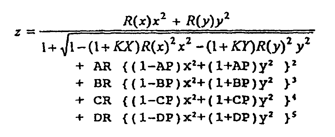
- the anamorphic aspherical surface is defined by the following expression:
- AR which is a low-order coefficient in expression (A) can assume a value of the same sign as the radius of curvature and which is not 0.
- R(x) and R(y) in expression (1) which are the radii of curvature in two directions orthogonal to each other which is greater in absolute value is defined as Rs
- the aspherical coefficient AR of the eyepiece reflecting surface satisfy the following conditional expression: 0 ⁇ AR/Rs ⁇ e -8
- the optical system of the image display apparatus of the present invention can also be used as the optical system of an image pickup apparatus.
- the eye point 17 in Figure 1 can be the entrance pupil and an image pickup element such as a CCD can be disposed at the position of the image display means 11. If at this time, a stop is provided at the eye point 17 or at the pupil position of the relay optical system 12, the adjustment of the quantity of light will be possible. Focus adjustment can be effected by moving a part or the whole of the refracting system 13 which is not decentered in the direction of the optical axis or moving the image pickup element.
- the reflecting surface 16 becomes a primary imaging optical system and the relay optical system 12 becomes a relay optical system for secondarily forming the image formed on the primary imaging plane by the reflecting surface 16.
- This construction also is a reflecting optical system and therefore, the image pickup element can be disposed at any other position than in the direction of incidence the ray at the central angle of view has at the entrance pupil, and the degree of freedom of spatial disposition becomes higher.
- a turn-back mirror is inserted in front of the refracting relay system, a construction in which a light is turned back in a zigzag shape will become possible, and an image pickup system which is thin relative to the direction of incidence at the entrance pupil can be realized.
- Each optical system is shown in terms of data by the so-called converse trace in which an image is formed on the image display surface with the eye point as the entrance pupil.
- the optical systems of the present invention each have at least one anamorphic aspherical surface in the eyepiece system or the relay system, and the shape thereof is prescribed by expression (A).
- the coordinates axes (x, y, z) in expression (A) are local coordinates systems with vertex coordinates on each surface as the origin, and the respective axes are defined as follows:
- the tilt angles of the i-th refracting surface and reflecting surface in yz plane are represented by an angle ⁇ i (unit is degree) in which the counter-clockwise direction relative to z axis is positive in yz plane.
- the amounts of shift ei of the i-th refracting surface and reflecting surface in yz plane are represented with y plus direction as the positive.
- the vertex of each optical element is on yz plane, and there is not the tilt of the optical element in xz and xy planes.
- i is a suffix indicating the i-th optical element as counted in the order in which the light passes from the observer's pupil side to the display surface
- Ri, Di, Ni and ⁇ i indicate the i-th radius of curvature, lens thickness or air gap distance, refractive index and abbe's number, respectively.
- the numerical value embodiments of the present invention define the positions of the respective surfaces in the order from the eye point toward the display surface.
- the eye point is defined as R0 surface for the sake of convenience and a point P0 is determined at this position
- a point P1' advanced by D0 in z plus direction of the local coordinates system at P0 becomes the origin of the local coordinates of R1 surface before the decentering thereof.
- the local coordinates system at the point P1' is the origin as it has been parallel-moved to P1' in the coordinates system of the point P0.
- a point P1 further moved from this point by the amount of shift e1 of R1 surface in y direction is the final local origin of R1 surface.
- the coordinates system is one in which the coordinates system of the point P1' has been rotated by a tilt angle ⁇ 1.
- R1 surface which is the reflecting surface is defined on this coordinates system by the above-described aspherical surface expression.
- a point P2' is determined by D1 and further, from e2 and ⁇ 2, the position of a point P2 is determined, and the shape of R2 surface is defined.
- a point P3' when a point P3' is to be determined from the point P2, it is set in z plus direction, and when a point P4' is to be determined from a point P3, it is set in z minus direction. Also, in the case of the refracting system, the direction immediately before is maintained and set. The sign of Ri is minus when the center of curvature is in z minus direction of each local coordinates system, and is plus when the center of curvature is in z plus direction.
- Optical paths corresponding to Numerical Value Embodiments 1 and 2 and Comparative Examples 1 to 3 are shown in Figures 5 to 9, lateral aberrations are shown in Figures 10 to 14, and image shapes are shown in Figures 15 to 19.
- the interior of the plane of the drawings sheet is the horizontal direction and a direction perpendicular to the plane of the drawing sheet is the vertical direction
- the image point position is represented by the angles of view in the horizontal direction and the vertical direction and moreover, the aberrations of the respective cross-sections in the horizontal direction and the vertical direction are described.
- a reflecting surface indicated by one stage R2 is inserted between the eyepiece reflecting surface R1 and the reflecting surface R3 of the relay optical system.
- Numerical Value Embodiment 1 is an embodiment in which two surfaces of the eyepiece reflecting surface R1 and the refracting surfaces of the relay optical system are aspherical surfaces
- Numerical Value Comparative Examples 1 and 3 are examples in which the eyepiece reflecting surface R1 and the reflecting surface R3 of the relay optical system are aspherical surfaces
- Numerical Value Example 4 is an embodiment in which in addition to R1 and R3, the intermediate mirror R2 is made aspherical
- Numerical Value Embodiment 5 is an embodiment in which with R1-R3, the refracting surfaces of the relay optical system are made aspherical.
- the dimension of the display surface is is 14.24 mm in the horizontal direction and 10.8 mm in the vertical direction
- the visibility is -1 diopter
- the angle of view obtained is 30.0° horizontally and 22.7° vertically.
Landscapes
- Physics & Mathematics (AREA)
- General Physics & Mathematics (AREA)
- Optics & Photonics (AREA)
- Lenses (AREA)
Claims (11)
- Bildanzeigegerät zur Anordnung in Kopfnähe eines Beobachters zum Beobachten eines Bilds, das auf einer Bildanzeigevorrichtung (11) als ein vergrößertes virtuelles Bild angezeigt ist, wobei das Bildanzeigegerät aufweist:wobei das Gerät dadurch gekennzeichnet ist, daß das optische Brechungssystem (13) mindestens eine Linse mit einer anamorphotischen, asphärischen Form aufweist, die sich in der Krümmung in jeder rechtwinkligen Richtung unterscheidet.ein optisches Übertragungssystem (12), um zu bewirken, daß das durch die Bildanzeigevorrichtung (11) angezeigte Bild als ein Zwischenbild (15) erzeugt wird, wobei das optische Übertragungssystem mindestens eine dezentrierte Reflexionsfläche (14; R3) zum Ablenken des Lichtstrahls von der Bildanzeigevorrichtung (11) und ein optisches Brechungssystem (13; R4 - R11) aufweist, undein optisches Okularsystem zum Richten des Bilds durch das optische Übertragungssystem zu der Pupille des Beobachters, wobei das optische Okularsystem mindestens eine dezentrierte Reflexionsfläche (16; R1) aufweist, welche eine anamorphotische, asphärische Oberfläche mit einer Konkavform zum Ablenken des Lichtstrahls von dem optischen Übertragungssystem (12) ist,
- Gerät gemäß Anspruch 1, wobei die dezentrierte Reflexionsfläche (14) des optischen Übertragungssystems (12) eine anamorphotische, asphärische Oberfläche (R3) ist.
- Gerät gemäß Anspruch 1, das ferner eine Spiegeloberfläche (R2) aufweist, die in dem optischen Pfad zwischen der dezentrierten Reflexionsfläche (R1) des optischen Okularsystems und der dezentrierten Reflexionsfläche (R3) des optischen Übertragungssystems (12) angeordnet ist.
- Gerät gemäß Anspruch 3, wobei die Spiegeloberfläche (R2) eine konvexe anamorphotische, asphärische Oberfläche ist.
- Gerät gemäß Anspruch 1, das die Beziehung
- Gerät gemäß Anspruch 5, wobei in der z-Richtung der optischen Achse die Form der anamorphotischen, asphärischen Oberfläche (R1) des Okularsystems definiert ist als:wobei der Koeffizient AR der asphärischen Oberfläche ein Wert mit dem gleichen Vorzeichen wie der Krümmungsradius ist, welcher nicht Null ist, und wenn die Krümmung in zwei rechtwinkligen Richtungen als Rs definiert ist, das Bildanzeigegerät die Beziehung erfüllt:
- Gerät gemäß Anspruch 1, wobei die Krümmung der konkaven anamorphotischen, asphärischen Reflexionsfläche in einer Richtung rechtwinklig zu der Richtung, in welche der Lichtstrahl durch die Dezentrierung der Reflexionsfläche abgelenkt wird, zu dem Rand hin kleiner ist.
- Gerät gemäß Anspruch 1, wobei die dezentrierte Reflexionsfläche (16; R1) des optischen Okularsystems eine Strahlteilvorrichtung ist.
- Bildaufnahmegerät zum Erzeugen des Bilds eines Objekts auf der Oberfläche eines Bildaufnahmeelements, das aufweist:ein Reflexionssystem (16) zum primären Abbilden eines Lichtstrahls von dem Objekt, wobei die Reflexionsfläche mindestens eine dezentrierte Reflexionsfläche aufweist, welche eine anamorphotische, asphärische Oberfläche mit einer konkaven Oberflächenform zum Ablenken des Lichtstrahls von dem Objekt ist, undein optisches Übertragungssystem (12) zum Richten des Bilds, das durch das Reflexionssystem (16) erzeugt ist, auf die Oberfläche des Bildaufnahmeelements, wobei das optische Übertragungssystem mindestens eine dezentrierte Reflexionsfläche (14) zum Ablenken des Lichtstrahls von dem Reflexionssystem (16) aufweist, und ein optisches Brechungssystem (13), das mindestens eine Linse (R4 - R11) einer anamorphotischen, asphärischen Form aufweist, die sich in der Krümmung in jeder rechtwinkligen Richtung unterscheidet.
- Gerät gemäß Anspruch 9, wobei die dezentrierte Reflexionsfläche (14) des optischen Übertragungssystems (12) eine anamorphotische, asphärische Oberfläche ist.
- Gerät gemäß Anspruch 9, das ferner eine Spiegeloberfläche (R2) aufweist, die in dem optischen Pfad zwischen der dezentrierten Reflexionsfläche des Reflexionssystems (16) und der dezentrierten Reflexionsfläche (14) des optischen Übertragungssystems (12) angeordnet ist.
Applications Claiming Priority (6)
| Application Number | Priority Date | Filing Date | Title |
|---|---|---|---|
| JP15097795 | 1995-05-25 | ||
| JP150977/95 | 1995-05-25 | ||
| JP15097795 | 1995-05-25 | ||
| JP14368696 | 1996-05-14 | ||
| JP8143686A JPH0943536A (ja) | 1995-05-25 | 1996-05-14 | 画像表示装置 |
| JP143686/96 | 1996-05-14 |
Publications (3)
| Publication Number | Publication Date |
|---|---|
| EP0744643A2 EP0744643A2 (de) | 1996-11-27 |
| EP0744643A3 EP0744643A3 (de) | 1997-01-15 |
| EP0744643B1 true EP0744643B1 (de) | 2002-09-18 |
Family
ID=26475355
Family Applications (1)
| Application Number | Title | Priority Date | Filing Date |
|---|---|---|---|
| EP96303725A Expired - Lifetime EP0744643B1 (de) | 1995-05-25 | 1996-05-24 | Optisches System für Head-up Anzeige |
Country Status (4)
| Country | Link |
|---|---|
| US (1) | US5687025A (de) |
| EP (1) | EP0744643B1 (de) |
| JP (1) | JPH0943536A (de) |
| DE (1) | DE69623687T2 (de) |
Cited By (1)
| Publication number | Priority date | Publication date | Assignee | Title |
|---|---|---|---|---|
| WO2023278465A1 (en) | 2021-06-29 | 2023-01-05 | Hes Ip Holdings, Llc | Optic system for head wearable devices |
Families Citing this family (38)
| Publication number | Priority date | Publication date | Assignee | Title |
|---|---|---|---|---|
| US6021004A (en) | 1995-02-28 | 2000-02-01 | Canon Kabushiki Kaisha | Reflecting type of zoom lens |
| DE69623362T2 (de) | 1995-02-28 | 2003-08-07 | Canon Kk | Zoomobjektiv mit reflektierenden Flächen |
| US6166866A (en) | 1995-02-28 | 2000-12-26 | Canon Kabushiki Kaisha | Reflecting type optical system |
| JPH09211331A (ja) * | 1996-01-29 | 1997-08-15 | Canon Inc | 反射光学系 |
| JP3761957B2 (ja) | 1996-02-15 | 2006-03-29 | キヤノン株式会社 | 反射型の光学系及びそれを用いた撮像装置 |
| JPH09261555A (ja) * | 1996-03-19 | 1997-10-03 | Olympus Optical Co Ltd | 画像表示装置 |
| US6034823A (en) * | 1997-02-07 | 2000-03-07 | Olympus Optical Co., Ltd. | Decentered prism optical system |
| FR2766931B1 (fr) * | 1997-08-01 | 1999-10-15 | Sextant Avionique | Dispositif optique pour viseur de casque comportant un miroir aspherique |
| FR2775358B1 (fr) * | 1998-02-20 | 2003-06-20 | Sextant Avionique | Dispositif optique pour viseur de casque comportant un miroir tubulaire |
| US6935747B2 (en) * | 1999-04-27 | 2005-08-30 | Optical Products Development | Image enhancement and aberration corrections in a small real image projection system |
| US6798579B2 (en) * | 1999-04-27 | 2004-09-28 | Optical Products Development Corp. | Real imaging system with reduced ghost imaging |
| US6612701B2 (en) * | 2001-08-20 | 2003-09-02 | Optical Products Development Corporation | Image enhancement in a real image projection system, using on-axis reflectors, at least one of which is aspheric in shape |
| DE60040181D1 (de) * | 1999-07-14 | 2008-10-16 | Nec Display Solutions Ltd | Durchsichtprotektionssystem mit schief einfallendem Lichtbündel |
| JP3840031B2 (ja) * | 2000-03-09 | 2006-11-01 | キヤノン株式会社 | 投射光学系及びそれを用いた投射型表示装置 |
| JP2002090692A (ja) * | 2000-07-10 | 2002-03-27 | Olympus Optical Co Ltd | 画像表示装置 |
| KR100762567B1 (ko) * | 2001-03-10 | 2007-10-01 | 엘지전자 주식회사 | 씨-쓰루 형 머리 장착용 표시 장치 |
| US20050094103A1 (en) * | 2001-08-20 | 2005-05-05 | Optical Products Development Corporation | Real image projection system for gaming, ATM, vending machines, merchandising displays and related applications |
| US20030035086A1 (en) * | 2001-08-20 | 2003-02-20 | Robinson Douglas L. | Real image projection device incorporating e-mail register |
| FR2853090B1 (fr) * | 2003-03-28 | 2005-06-10 | Valeo Vision | Procede d'affichage d'une image sur un pare-brise de vehicule et dispositif de mise en oeuvre. |
| US8210694B1 (en) * | 2007-07-03 | 2012-07-03 | University Of South Florida | Pair of concave mirrors for projecting non-inverted real images |
| GB2458898A (en) * | 2008-03-31 | 2009-10-07 | Semelab Plc | A head up display system with ghost image elimination means |
| JP4911129B2 (ja) * | 2008-07-08 | 2012-04-04 | 株式会社島津製作所 | 表示装置 |
| US8029140B2 (en) | 2008-09-18 | 2011-10-04 | Disney Enterprises, Inc. | Device to produce a floating image |
| US8042948B2 (en) * | 2008-09-18 | 2011-10-25 | Disney Enterprises, Inc. | Apparatus that produces a three-dimensional image |
| US9239415B2 (en) * | 2012-03-08 | 2016-01-19 | Google Inc. | Near-to-eye display with an integrated out-looking camera |
| CN105209953B (zh) | 2013-03-15 | 2020-01-03 | 依米有限公司 | 通过结构框架保持对准的头戴式显示器 |
| JP2018010251A (ja) * | 2016-07-15 | 2018-01-18 | 京セラ株式会社 | 虚像表示装置 |
| CN107367842A (zh) * | 2017-08-30 | 2017-11-21 | 深圳超多维科技有限公司 | 一种头戴式显示设备 |
| JP6656213B2 (ja) * | 2017-08-31 | 2020-03-04 | キヤノン株式会社 | 画像表示装置 |
| JP2021033154A (ja) | 2019-08-28 | 2021-03-01 | セイコーエプソン株式会社 | 虚像表示装置及び導光装置 |
| JP2022072205A (ja) | 2020-10-29 | 2022-05-17 | セイコーエプソン株式会社 | 表示モジュール、表示モジュールの組み立て方法および虚像表示装置 |
| JP2022071923A (ja) | 2020-10-29 | 2022-05-17 | セイコーエプソン株式会社 | 虚像表示装置及び光学ユニット |
| JP2022071922A (ja) | 2020-10-29 | 2022-05-17 | セイコーエプソン株式会社 | 虚像表示装置及び光学ユニット |
| JP2022086170A (ja) | 2020-11-30 | 2022-06-09 | セイコーエプソン株式会社 | 表示装置及び光学ユニット |
| WO2023052282A1 (en) * | 2021-09-29 | 2023-04-06 | Wayray Ag | Optical system of augmented reality head-up display |
| US20230096336A1 (en) * | 2021-09-29 | 2023-03-30 | Wayray Ag | Optical system of augmented reality head-up display |
| JP2024010699A (ja) * | 2022-07-13 | 2024-01-25 | 株式会社リコー | 虚像表示装置用光学系、虚像表示装置及びヘッドマウントディスプレイ |
| WO2025028463A1 (ja) * | 2023-07-31 | 2025-02-06 | 京セラ株式会社 | 光学装置および浮遊像表示装置 |
Family Cites Families (13)
| Publication number | Priority date | Publication date | Assignee | Title |
|---|---|---|---|---|
| IL99420A (en) * | 1991-09-05 | 2000-12-06 | Elbit Systems Ltd | Helmet mounted display |
| JP3310325B2 (ja) * | 1992-04-28 | 2002-08-05 | オリンパス光学工業株式会社 | ヘッドマウントディスプレイ装置及びそれを用いたシステム |
| JP3155360B2 (ja) * | 1992-07-27 | 2001-04-09 | オリンパス光学工業株式会社 | 視覚表示装置 |
| US5473365A (en) * | 1992-12-25 | 1995-12-05 | Olympus Optical Co., Ltd. | Head-mounted image display apparatus in which a system is capable of changing aspect ratio of observed image |
| JPH06194598A (ja) * | 1992-12-25 | 1994-07-15 | Olympus Optical Co Ltd | 頭部装着型ディスプレイ装置 |
| JPH06242396A (ja) * | 1992-12-25 | 1994-09-02 | Olympus Optical Co Ltd | 頭部装着型映像表示装置 |
| JP3212203B2 (ja) * | 1993-02-09 | 2001-09-25 | オリンパス光学工業株式会社 | 視覚表示装置 |
| US5384654A (en) * | 1993-05-10 | 1995-01-24 | Olympus Optical Co., Ltd. | Image observation device |
| JPH06324285A (ja) * | 1993-05-13 | 1994-11-25 | Olympus Optical Co Ltd | 視覚表示装置 |
| EP0632303B1 (de) * | 1993-06-30 | 2001-04-25 | Canon Kabushiki Kaisha | Bildwiedergabegerät |
| US5473499A (en) * | 1993-06-30 | 1995-12-05 | Harris Corporation | Hot pluggable motherboard bus connection method |
| US5526183A (en) * | 1993-11-29 | 1996-06-11 | Hughes Electronics | Helmet visor display employing reflective, refractive and diffractive optical elements |
| JPH07191274A (ja) * | 1993-12-27 | 1995-07-28 | Canon Inc | 画像表示装置 |
-
1996
- 1996-05-14 JP JP8143686A patent/JPH0943536A/ja active Pending
- 1996-05-22 US US08/651,298 patent/US5687025A/en not_active Expired - Lifetime
- 1996-05-24 DE DE69623687T patent/DE69623687T2/de not_active Expired - Lifetime
- 1996-05-24 EP EP96303725A patent/EP0744643B1/de not_active Expired - Lifetime
Cited By (2)
| Publication number | Priority date | Publication date | Assignee | Title |
|---|---|---|---|---|
| WO2023278465A1 (en) | 2021-06-29 | 2023-01-05 | Hes Ip Holdings, Llc | Optic system for head wearable devices |
| EP4204895A4 (de) * | 2021-06-29 | 2024-09-18 | HES IP Holdings, LLC | Optisches system für am kopf tragbare vorrichtungen |
Also Published As
| Publication number | Publication date |
|---|---|
| DE69623687D1 (de) | 2002-10-24 |
| EP0744643A2 (de) | 1996-11-27 |
| JPH0943536A (ja) | 1997-02-14 |
| EP0744643A3 (de) | 1997-01-15 |
| US5687025A (en) | 1997-11-11 |
| DE69623687T2 (de) | 2003-05-22 |
Similar Documents
| Publication | Publication Date | Title |
|---|---|---|
| US5687025A (en) | Image display apparatus and image pickup apparatus | |
| EP0660155B1 (de) | Vorrichtung zum Anzeigen von Bildern | |
| US6008778A (en) | Visual display apparatus | |
| US6317267B1 (en) | Head or face mounted image display apparatus | |
| USRE37175E1 (en) | Image display apparatus | |
| JP3487859B2 (ja) | ヘッドマウントディスプレー装置及び該装置に用いるディスプレー用光学系 | |
| US7420751B2 (en) | Compact optical apparatus for head up display | |
| JP3658034B2 (ja) | 画像観察光学系及び撮像光学系 | |
| US6181475B1 (en) | Optical system and image display apparatus | |
| US6046857A (en) | Head mounted image display apparatus | |
| US6185045B1 (en) | Image display apparatus with mechanism for modifying the appearance of the periphery of a display device | |
| US5594588A (en) | Visual display | |
| JP3672951B2 (ja) | 画像表示装置 | |
| US5790311A (en) | Ocular optics system having at least four reflections occurring between curved surfaces | |
| USRE37292E1 (en) | Optical system and optical apparatus | |
| US7081999B2 (en) | Image display apparatus and head mounted display using it | |
| EP0790516A1 (de) | Bildanzeigegerät | |
| US20020163734A1 (en) | Optical element and compound display apparatus using the same | |
| JP3929099B2 (ja) | 映像表示装置 | |
| JP3155335B2 (ja) | 視覚表示装置 | |
| JP3155337B2 (ja) | 視覚表示装置 | |
| US7391575B2 (en) | Image display apparatus | |
| US6853356B2 (en) | Optical system and image displaying apparatus using the same | |
| JP3155336B2 (ja) | 視覚表示装置 | |
| JP3486465B2 (ja) | 視覚表示装置 |
Legal Events
| Date | Code | Title | Description |
|---|---|---|---|
| PUAI | Public reference made under article 153(3) epc to a published international application that has entered the european phase |
Free format text: ORIGINAL CODE: 0009012 |
|
| AK | Designated contracting states |
Kind code of ref document: A2 Designated state(s): DE ES FR GB IT NL |
|
| PUAL | Search report despatched |
Free format text: ORIGINAL CODE: 0009013 |
|
| AK | Designated contracting states |
Kind code of ref document: A3 Designated state(s): DE ES FR GB IT NL |
|
| 17P | Request for examination filed |
Effective date: 19970528 |
|
| 17Q | First examination report despatched |
Effective date: 19991126 |
|
| GRAG | Despatch of communication of intention to grant |
Free format text: ORIGINAL CODE: EPIDOS AGRA |
|
| GRAG | Despatch of communication of intention to grant |
Free format text: ORIGINAL CODE: EPIDOS AGRA |
|
| GRAG | Despatch of communication of intention to grant |
Free format text: ORIGINAL CODE: EPIDOS AGRA |
|
| GRAH | Despatch of communication of intention to grant a patent |
Free format text: ORIGINAL CODE: EPIDOS IGRA |
|
| GRAH | Despatch of communication of intention to grant a patent |
Free format text: ORIGINAL CODE: EPIDOS IGRA |
|
| GRAA | (expected) grant |
Free format text: ORIGINAL CODE: 0009210 |
|
| AK | Designated contracting states |
Kind code of ref document: B1 Designated state(s): DE ES FR GB IT NL |
|
| PG25 | Lapsed in a contracting state [announced via postgrant information from national office to epo] |
Ref country code: NL Free format text: LAPSE BECAUSE OF FAILURE TO SUBMIT A TRANSLATION OF THE DESCRIPTION OR TO PAY THE FEE WITHIN THE PRESCRIBED TIME-LIMIT Effective date: 20020918 Ref country code: IT Free format text: LAPSE BECAUSE OF FAILURE TO SUBMIT A TRANSLATION OF THE DESCRIPTION OR TO PAY THE FEE WITHIN THE PRESCRIBED TIME-LIMIT;WARNING: LAPSES OF ITALIAN PATENTS WITH EFFECTIVE DATE BEFORE 2007 MAY HAVE OCCURRED AT ANY TIME BEFORE 2007. THE CORRECT EFFECTIVE DATE MAY BE DIFFERENT FROM THE ONE RECORDED. Effective date: 20020918 |
|
| REG | Reference to a national code |
Ref country code: GB Ref legal event code: FG4D |
|
| REF | Corresponds to: |
Ref document number: 69623687 Country of ref document: DE Date of ref document: 20021024 |
|
| ET | Fr: translation filed | ||
| NLV1 | Nl: lapsed or annulled due to failure to fulfill the requirements of art. 29p and 29m of the patents act | ||
| PG25 | Lapsed in a contracting state [announced via postgrant information from national office to epo] |
Ref country code: ES Free format text: LAPSE BECAUSE OF FAILURE TO SUBMIT A TRANSLATION OF THE DESCRIPTION OR TO PAY THE FEE WITHIN THE PRESCRIBED TIME-LIMIT Effective date: 20030328 |
|
| PLBE | No opposition filed within time limit |
Free format text: ORIGINAL CODE: 0009261 |
|
| STAA | Information on the status of an ep patent application or granted ep patent |
Free format text: STATUS: NO OPPOSITION FILED WITHIN TIME LIMIT |
|
| 26N | No opposition filed |
Effective date: 20030619 |
|
| PGFP | Annual fee paid to national office [announced via postgrant information from national office to epo] |
Ref country code: FR Payment date: 20090520 Year of fee payment: 14 |
|
| REG | Reference to a national code |
Ref country code: FR Ref legal event code: ST Effective date: 20110131 |
|
| PG25 | Lapsed in a contracting state [announced via postgrant information from national office to epo] |
Ref country code: FR Free format text: LAPSE BECAUSE OF NON-PAYMENT OF DUE FEES Effective date: 20100531 |
|
| PGFP | Annual fee paid to national office [announced via postgrant information from national office to epo] |
Ref country code: GB Payment date: 20140523 Year of fee payment: 19 |
|
| PGFP | Annual fee paid to national office [announced via postgrant information from national office to epo] |
Ref country code: DE Payment date: 20140531 Year of fee payment: 19 |
|
| REG | Reference to a national code |
Ref country code: DE Ref legal event code: R119 Ref document number: 69623687 Country of ref document: DE |
|
| GBPC | Gb: european patent ceased through non-payment of renewal fee |
Effective date: 20150524 |
|
| PG25 | Lapsed in a contracting state [announced via postgrant information from national office to epo] |
Ref country code: GB Free format text: LAPSE BECAUSE OF NON-PAYMENT OF DUE FEES Effective date: 20150524 Ref country code: DE Free format text: LAPSE BECAUSE OF NON-PAYMENT OF DUE FEES Effective date: 20151201 |