EP0744482B1 - Verstellbare Klammer für die Schwenkverbindung der Schwingarme einer Schaftmaschine mit den Hebeln des Hebesystems - Google Patents
Verstellbare Klammer für die Schwenkverbindung der Schwingarme einer Schaftmaschine mit den Hebeln des Hebesystems Download PDFInfo
- Publication number
- EP0744482B1 EP0744482B1 EP96420188A EP96420188A EP0744482B1 EP 0744482 B1 EP0744482 B1 EP 0744482B1 EP 96420188 A EP96420188 A EP 96420188A EP 96420188 A EP96420188 A EP 96420188A EP 0744482 B1 EP0744482 B1 EP 0744482B1
- Authority
- EP
- European Patent Office
- Prior art keywords
- stirrup
- frame
- wedge
- clip
- jaws
- Prior art date
- Legal status (The legal status is an assumption and is not a legal conclusion. Google has not performed a legal analysis and makes no representation as to the accuracy of the status listed.)
- Expired - Lifetime
Links
Images


Classifications
-
- D—TEXTILES; PAPER
- D03—WEAVING
- D03C—SHEDDING MECHANISMS; PATTERN CARDS OR CHAINS; PUNCHING OF CARDS; DESIGNING PATTERNS
- D03C1/00—Dobbies
- D03C1/14—Features common to dobbies of different types
- D03C1/144—Features common to dobbies of different types linking to the heald frame
-
- F—MECHANICAL ENGINEERING; LIGHTING; HEATING; WEAPONS; BLASTING
- F16—ENGINEERING ELEMENTS AND UNITS; GENERAL MEASURES FOR PRODUCING AND MAINTAINING EFFECTIVE FUNCTIONING OF MACHINES OR INSTALLATIONS; THERMAL INSULATION IN GENERAL
- F16B—DEVICES FOR FASTENING OR SECURING CONSTRUCTIONAL ELEMENTS OR MACHINE PARTS TOGETHER, e.g. NAILS, BOLTS, CIRCLIPS, CLAMPS, CLIPS OR WEDGES; JOINTS OR JOINTING
- F16B2200/00—Constructional details of connections not covered for in other groups of this subclass
- F16B2200/69—Redundant disconnection blocking means
-
- Y—GENERAL TAGGING OF NEW TECHNOLOGICAL DEVELOPMENTS; GENERAL TAGGING OF CROSS-SECTIONAL TECHNOLOGIES SPANNING OVER SEVERAL SECTIONS OF THE IPC; TECHNICAL SUBJECTS COVERED BY FORMER USPC CROSS-REFERENCE ART COLLECTIONS [XRACs] AND DIGESTS
- Y10—TECHNICAL SUBJECTS COVERED BY FORMER USPC
- Y10T—TECHNICAL SUBJECTS COVERED BY FORMER US CLASSIFICATION
- Y10T403/00—Joints and connections
- Y10T403/70—Interfitted members
- Y10T403/7062—Clamped members
- Y10T403/7064—Clamped members by wedge or cam
- Y10T403/7066—Clamped members by wedge or cam having actuator
- Y10T403/7067—Threaded actuator
- Y10T403/7069—Axially oriented
Definitions
- the present invention relates to armor mechanics for training of the crowd on the looms and it concerns more particularly the adjustable clips which ensure the pivoting assembly of swing arms of the mechanics with the connecting rods of the system draw associated with heald frames of the trade.
- such a clip, referenced 1 is likely to be immobilized at any position along the axis of one swing arms 2 (arrow F1) of mechanics 3, which allows adjust the amplitude of the vertical travel of the heald frame CL which is hitched to the connecting rod 4. Furthermore the hitch point 5 carried by clip 1 for the articulation of the connecting rod 4 can be moved following arrow F2, thereby authorizing the height adjustment of the CL frame in relation to the loom.
- Document FR-A-2 398 136 shows an adjustable clip constituted by a tubular piece 6 (see fig. 2) forming a frame, which carries at one of its ends the axis 5 of the coupling point.
- This part 6 is cut out by a notch 6 a which is crossed with a large clearance by the oscillating arm 2 considered, which is surrounded on three sides by the bottom of a stirrup 7 oriented axially inside the part 1 and movable therein in the manner of a slide.
- the immobilization of this stirrup or slide 7 along the arm 2 is ensured by a jaw 8 controlled by two opposite lateral ramps 9 themselves actuated by means of a central corner 10.
- the latter is associated with a screw thrust 11 screwed into the thread of a die 12 secured to the free ends of the wings of the stirrup 7; this die 12 receives the action of an adjustment screw 13 with two opposite threads which cooperates with a spacer 14 carried by the end of the part 6 opposite to that equipped with the axis or point 5.
- the screw 13 allows the adjustment of the axial position of the part 6 with respect to the slide or stirrup 7 and, consequently, of the point 5 relative to the connecting rod 4, while the operation of the screw 11 ensures the immobilization of this part 6 at the desired height along the arm 2.
- fig. 1 illustrates the function of a staple adjustable while fig. 2 reflects the prior art disclosed by the document FR-A-2 398 136 referred to above.
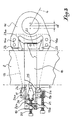
- Fig. 3 is a side view with cutaway, representing a staple established in accordance with the present invention.
- Fig. 4 shows in perspective, prior to their mounting, the different components of the clip according to fig. 3.
- the clip shown in fig. 3 and 4 comprises a main part 15 forming a frame, constituted by a sole against one of the faces of which are attached, by riveting in the embodiment envisaged, on the one hand an eyelet 16 intended to receive the axis for the articulated coupling of the connecting rod 4 of the pulling system associated with the mechanics, on the other hand (in fact in the vicinity of the opposite end of the sole) two protruding guides 17. It will be observed that the eyelet 16 itself has two raised portions 16 has also forming guides, as will be understood better later.
- the frame 15 thus arranged is associated with a slide 18 in the form of a stirrup which opens opposite the eyelet 16; the free ends of the two wings of this slide 18 are joined to each other by a spacer 19 pierced with a central thread inside which is engaged a push screw 20.
- a spacer 19 In a lateral lug 19 a of l the spacer 19 is screwed one of the two opposite threads with a double adjusting screw 21, the other thread cooperating with a thread formed in a lateral lug 17 a from one of the two guides 17 of the frame 15.
- the bottom of the stirrup 18 is equipped with an overhanging corner 22 whose oblique edges cooperate with two profiled jaws 23 which laterally bear against the guides 16 a .
- the guides 17 form supports for two profiled jaws 24 cooperating with a central corner 25.
- a spring 26 is interposed between the ends opposite the corner 25 and the push screw 20 .
- the clip in the assembled state is first engaged on the swingarm 2 intended for him; to do this, just introduce the stirrup 18 on arm 2 which is housed between the two wings of said stirrup, in the portion of it between the central jaw 22 and the two side jaws 24.
- the screw 20 is slightly tightened to transmit to the corner 25, by through the spring 26, and from there to the two jaws 24, a slight pressure.
- the screw 20 acts, by pulling on the stirrup via the spacer 19, on the corner 22 and, from there, on the jaws 23.
- the reduced tightening of screw 20 temporarily prevents sliding of the clip along the arm 2, the slight friction obtained compensating the effect of gravity until complete tightening.
- the operator maneuvers the adjusting screw 21 to move the frame 15, and consequently the eyelet 16 (distance d of fig. 3), relative to the stirrup as a function of the desired height for the heald frame CL .
- the operator tightens the screw 20 to ensure the final blocking of the clip, that is to say on the one hand fix its position along the arm 2 in function of the amplitude of the desired stroke for the heald frame CL considered, and secondly the position of the eyecup 16.
- This double blockage results from the simultaneous action of the ramps of the corners 22 and 25 on the combined ramps of jaws 23 and 24, the screw 20 pushing the wedge central 25 towards the bottom of the stirrup while pulling the corner 22 in the opposite direction.
- each jaw 23 has a beak 23 a , directed towards the opposite jaw 23, at its end opposite to the arm 2.
Landscapes
- Engineering & Computer Science (AREA)
- Textile Engineering (AREA)
- Clamps And Clips (AREA)
- Looms (AREA)
- Maintenance And Inspection Apparatuses For Elevators (AREA)
- Paper (AREA)
- Window Of Vehicle (AREA)
Claims (9)
- Verstellbare Klammer für die Schwenkverbindung der Schwingarme (2) einer Schaftmaschine (3) mit den Hebeln (4) eines Ziehsystems, das den Schaftrahmen (CL) eines Webstuhls zugeordnet ist, einer solchen Art, die einen Bügel (18) in Form eines Schlittens umfaßt, der dazu dient, an drei Seiten den betrachteten Schwingarm (2) zu umgeben, der mit Spiel durch den durchbrochenen Träger (15) der Klammer hindurchgeht und die mit einem Betätigungsmechanismus versehen ist, der ausgebildet ist, um auf bewegliche Spannbacken (24) zu wirken, die im Inneren des Bügels an einer Seite des Armes angeordnet sind, um einerseits die Festlegung des Trägers längs des Armes und andererseits die Einstellung in Position des Trägers senkrecht zur Achse des Arms sicherzustellen, wobei der Träger mit zwei ersten seitlichen Führungen (17) für zwei Backen (24) versehen ist, die mit Hilfe eines ersten mittleren Keils (25) betätigt werden, der zwischen den freien Enden der Schenkel des Bügels angeordnet ist, während der Betätigungsmechanismus eine Schraube (20) umfaßt, die in das Gewinde eines Abstandssteges (19) eingreift, der zwischen den zwei freien Enden der Schenkel des Bügels (18) angeordnet ist,
dadurch gekennzeichnet,
daß der Träger (15) mit zwei zweiten seitlichen Führungen (16a) für zwei Backen (23) versehen ist, die auf der anderen Seite des Armes angeordnet sind und einem zweiten Betätigungskeil (22) zugeordnet sind, der mit dem Boden des Bügels (18) in Kontakt ist und daß die Schraube (20) ausgebildet ist, um den ersten Keil (25) zum Boden des Bügels zu drücken, wobei der zweite Keil (22) in die entgegengesetzte Richtung gezogen wird. - Klammer nach Anspruch 1, dadurch gekennzeichnet, daß zwischen der Schubschraube (20) und dem mittleren Keil (25) ein elastisches Mittel (26) angeordnet ist, das auf den Keil wirkt, um durch Reibung den provisorischen Halt der Klammer längs des Schwingarmes (2) sicherzustellen.
- Klammer nach einem der Ansprüche 1 oder 2, dadurch gekennzeichnet, daß die Position des Trägeres (15) in Bezug auf den Bügel (18) in an sich bekannter Weise durch eine Einstellschraube (21) mit zwei entgegengesetzten Gewinden eingestellt wird, die mit zwei jeweils fest mit dem Steg (19) des Bügels (18) und dem Träger (15) verbundenen seitlichen Ohren (17a und 19a) zusammenarbeiten.
- Klammer nach einem der Ansprüche 1 bis 3, dadurch gekennzeichnet, daß der Träger (15) eine Sohle (15) aufweist, die an einem Ende fest mit einem Auge (16) mit zwei seitlichen Vorsprüngen (16a), die die ersten seitlichen Führungen bilden und am anderen Ende mit zwei anderen seitlichen Vorsprüngen (17) verbunden ist, die die zweiten seitlichen Führungen bilden.
- Klammer nach Anspruch 4, dadurch gekennzeichnet, daß die Sohle des Trägers (15) durch eine Längsvertiefung (15a) ausgehöhlt ist, die die Führung für den Bügel (18) bildet, während die Vorsprünge oder Führungen (17) dieses Trägers einen Stegansatz (17b) aufweisen, der zwischen die Längsschenkel des Bügels eingeführt ist.
- Klammer nach einem der vorhergehenden Ansprüche, dadurch gekennzeichnet, daß der zweite Keil (22) am Boden des Bügels (18) angeordnet ist.
- Klammer nach einem der vorhergehenden Ansprüche, dadurch gekennzeichnet, daß der zweite Keil (22) schräge Ränder aufweist, die geeignet sind, mit den zugeordneten-Backen (23) zusammenzuarbeiten.
- Klammer nach einem der vorhergehenden Ansprüche, dadurch gekennzeichnet, daß die Schraube (20) geeignet ist, durch Zug auf den Bügel (18), auf den zweiten Keil (22) und auf die zugeordneten Backen (23) zu wirken.
- Klammer nach einem der vorhergehenden Ansprüche, dadurch gekennzeichnet, daß die Backen (23, 24) mit Nasen (23a, 24a, 24b) für eine Unverlierbarkeit versehen sind.
Applications Claiming Priority (2)
| Application Number | Priority Date | Filing Date | Title |
|---|---|---|---|
| FR9506416A FR2734610B1 (fr) | 1995-05-24 | 1995-05-24 | Agrafe reglable pour l'assemblage pivotant des bras oscillants d'une mecanique d'armure avec les bielles d'attaque du systeme de tirage |
| FR9506416 | 1995-05-24 |
Publications (3)
| Publication Number | Publication Date |
|---|---|
| EP0744482A2 EP0744482A2 (de) | 1996-11-27 |
| EP0744482A3 EP0744482A3 (de) | 1998-12-30 |
| EP0744482B1 true EP0744482B1 (de) | 2001-07-11 |
Family
ID=9479509
Family Applications (1)
| Application Number | Title | Priority Date | Filing Date |
|---|---|---|---|
| EP96420188A Expired - Lifetime EP0744482B1 (de) | 1995-05-24 | 1996-05-23 | Verstellbare Klammer für die Schwenkverbindung der Schwingarme einer Schaftmaschine mit den Hebeln des Hebesystems |
Country Status (5)
| Country | Link |
|---|---|
| US (1) | US5685346A (de) |
| EP (1) | EP0744482B1 (de) |
| JP (1) | JP3628104B2 (de) |
| DE (1) | DE69613762T2 (de) |
| FR (1) | FR2734610B1 (de) |
Families Citing this family (9)
| Publication number | Priority date | Publication date | Assignee | Title |
|---|---|---|---|---|
| IT1295386B1 (it) * | 1997-10-23 | 1999-05-12 | Fimtextile Spa | Dispositivo di regolazione della testa della tiranteria di comando dei quadri dei licci in un telaio tessile |
| FR2776307B1 (fr) * | 1998-03-19 | 2000-06-23 | Staubli Sa Ets | Mecanisme de tirage pour mecanique d'armure et metier a tisser comprenant un tel mecanisme de tirage |
| FR2836488B1 (fr) * | 2002-02-28 | 2004-06-04 | Staubli Sa Ets | Mecanisme de tirage, son procede de fabrication et metier a tisser comprenant un tel mecanisme |
| BE1016217A5 (nl) * | 2004-09-28 | 2006-05-02 | Wiele Michel Van De Nv | Gaapvormingsinrichting en weefmachine voorzien van dergelijke gaapvormingsinrichting. |
| US7475708B2 (en) * | 2004-11-17 | 2009-01-13 | Groz-Beckert Kg | Shaft drive for heald shafts of weaving machines |
| FR2913079B1 (fr) | 2007-02-22 | 2010-01-01 | Staubli Sa Ets | Roulement pour metier a tisser avec cavite de lubrification et systeme de tirage de metier a tisser comprenant un tel roulement |
| FR3002546B1 (fr) | 2013-02-25 | 2015-08-14 | Staubli Sa Ets | Bielle appartenant a un metier a tisser et metier a tisser comprenant cette bielle |
| FR3126714B1 (fr) | 2021-09-06 | 2023-09-08 | Staubli Sa Ets | Machine de formation de la foule pour un métier à tisser et son procédé de réglage |
| FR3132108B1 (fr) | 2022-01-27 | 2024-01-26 | Staubli Sa Ets | Ensemble de formation de la foule pour un métier à tisser et son procédé de réglage |
Family Cites Families (5)
| Publication number | Priority date | Publication date | Assignee | Title |
|---|---|---|---|---|
| CH621159A5 (de) * | 1977-07-20 | 1981-01-15 | Staeubli Ag | |
| EP0252177B1 (de) * | 1986-07-09 | 1990-02-07 | Kaiser GmbH & Co. KG | Vorrichtung zum Verbinden eines Schwingarmes einer Schaftmaschine mit einem Schaft einer Webmaschine |
| IT1258971B (it) * | 1992-06-11 | 1996-03-11 | Costantino Vinciguerra | Tirante perfezionato di collegamento registrabile tra la ratiera e le leve a squadra della tiranteria di comando quadri di un telaio tessile |
| FR2705972B1 (fr) * | 1993-06-03 | 1995-07-21 | Staubli Sa Ets | Dispositif amortisseur pour machine à tisser. |
| EP0633335A1 (de) * | 1993-07-05 | 1995-01-11 | Stäubli AG (Stäubli SA) (Stäubli Ltd.) | Justiereinrichtung im Verbindungsweg zwischen dem Schwingarm einer Schaftmaschine und einem Schaft einer Webmaschine |
-
1995
- 1995-05-24 FR FR9506416A patent/FR2734610B1/fr not_active Expired - Fee Related
-
1996
- 1996-05-15 US US08/648,402 patent/US5685346A/en not_active Expired - Fee Related
- 1996-05-21 JP JP12611496A patent/JP3628104B2/ja not_active Expired - Lifetime
- 1996-05-23 DE DE69613762T patent/DE69613762T2/de not_active Expired - Lifetime
- 1996-05-23 EP EP96420188A patent/EP0744482B1/de not_active Expired - Lifetime
Also Published As
| Publication number | Publication date |
|---|---|
| EP0744482A3 (de) | 1998-12-30 |
| JP3628104B2 (ja) | 2005-03-09 |
| FR2734610B1 (fr) | 1997-07-04 |
| US5685346A (en) | 1997-11-11 |
| FR2734610A1 (fr) | 1996-11-29 |
| JPH08325879A (ja) | 1996-12-10 |
| DE69613762D1 (de) | 2001-08-16 |
| DE69613762T2 (de) | 2002-04-25 |
| EP0744482A2 (de) | 1996-11-27 |
Similar Documents
| Publication | Publication Date | Title |
|---|---|---|
| EP0744482B1 (de) | Verstellbare Klammer für die Schwenkverbindung der Schwingarme einer Schaftmaschine mit den Hebeln des Hebesystems | |
| EP0582803B1 (de) | Schischuh | |
| FR2570997A1 (fr) | Toit ouvrant relevable dont le verrouillage est autocommande, sans mecanismes additionnels | |
| FR2663234A1 (fr) | Support pour fixations de ski. | |
| EP0297003B1 (de) | Vorrichtung zum Kuppeln von Schaftrahmen mit den Transmissionselementen der Schaftmaschine | |
| EP0117826B1 (de) | Einhängevorrichtung für die halbautomatische Verbindung zwischen den Schaftrahmen und ihren Steuerhebln | |
| FR2688822A1 (fr) | Dispositif de fixation d'un operateur pour la commande d'ouverture et de fermeture d'un vantail de porte ou portail. | |
| EP0216717B1 (de) | Klemmzange mit selbsteinstellenden Backen | |
| CH616511A5 (en) | Spring hinge for spectacles | |
| FR2466543A1 (fr) | Dispositif servant a coupler un element de tirage des lames a un cadre porte-lisses | |
| FR2548127A1 (fr) | Dispositif de fixation d'un accessoire sur un cycle | |
| EP0943708A1 (de) | Zugvorrichtung für Fachbildungsmechanismen und Webmaschine mit einer solchen Vorrichtung | |
| FR2690177A1 (fr) | Mécanisme de verrouillage d'un instrument sur un tracteur. | |
| EP0514299A1 (de) | Zwischen Schaftmaschine und Webschäfte eingebaute Hebelzugvorrichtung | |
| FR2642657A1 (fr) | Fixation de securite pour ski destinee a maintenir l'avant d'une chaussure sur un ski | |
| FR2787283A1 (fr) | Dispositif de retenue avec un ressort pour un outil agricole en particulier un outil de labourage | |
| BE702816A (de) | ||
| FR2550048A1 (fr) | Charrue brabant ou reversible a attelage ou a selle | |
| EP1747312B1 (de) | Mechanismus zur bildung eines webfachs und mit dem webfach ausgerüstete webmaschine | |
| FR2642656A1 (fr) | Fixation de securite pour ski destinee a maintenir l'avant d'une chaussure montee sur le ski | |
| EP0491412A1 (de) | Vorrichtung zum Fixieren eines Elementes in ein Gestell | |
| FR2684016A1 (fr) | Element de fixation de securite de ski alpin. | |
| BE438253A (de) | ||
| FR2718254A1 (fr) | Lunettes, notamment de vue ou solaires, et monture s'y rapportant. | |
| FR2627095A1 (fr) | Fixation de securite pour ski |
Legal Events
| Date | Code | Title | Description |
|---|---|---|---|
| PUAI | Public reference made under article 153(3) epc to a published international application that has entered the european phase |
Free format text: ORIGINAL CODE: 0009012 |
|
| AK | Designated contracting states |
Kind code of ref document: A2 Designated state(s): BE CH DE FR GB IT LI |
|
| PUAL | Search report despatched |
Free format text: ORIGINAL CODE: 0009013 |
|
| AK | Designated contracting states |
Kind code of ref document: A3 Designated state(s): BE CH DE FR GB IT LI |
|
| ITCL | It: translation for ep claims filed |
Representative=s name: MODIANO & ASSOCIATI S.R.L. |
|
| 17P | Request for examination filed |
Effective date: 19990505 |
|
| GRAG | Despatch of communication of intention to grant |
Free format text: ORIGINAL CODE: EPIDOS AGRA |
|
| GRAG | Despatch of communication of intention to grant |
Free format text: ORIGINAL CODE: EPIDOS AGRA |
|
| 17Q | First examination report despatched |
Effective date: 19990818 |
|
| GRAG | Despatch of communication of intention to grant |
Free format text: ORIGINAL CODE: EPIDOS AGRA |
|
| GRAH | Despatch of communication of intention to grant a patent |
Free format text: ORIGINAL CODE: EPIDOS IGRA |
|
| GRAH | Despatch of communication of intention to grant a patent |
Free format text: ORIGINAL CODE: EPIDOS IGRA |
|
| GRAA | (expected) grant |
Free format text: ORIGINAL CODE: 0009210 |
|
| AK | Designated contracting states |
Kind code of ref document: B1 Designated state(s): BE CH DE FR GB IT LI |
|
| REG | Reference to a national code |
Ref country code: CH Ref legal event code: EP |
|
| REF | Corresponds to: |
Ref document number: 69613762 Country of ref document: DE Date of ref document: 20010816 |
|
| GBT | Gb: translation of ep patent filed (gb section 77(6)(a)/1977) |
Effective date: 20010831 |
|
| ITF | It: translation for a ep patent filed | ||
| REG | Reference to a national code |
Ref country code: GB Ref legal event code: IF02 |
|
| PLBE | No opposition filed within time limit |
Free format text: ORIGINAL CODE: 0009261 |
|
| STAA | Information on the status of an ep patent application or granted ep patent |
Free format text: STATUS: NO OPPOSITION FILED WITHIN TIME LIMIT |
|
| 26N | No opposition filed | ||
| PGFP | Annual fee paid to national office [announced via postgrant information from national office to epo] |
Ref country code: GB Payment date: 20040518 Year of fee payment: 9 |
|
| PG25 | Lapsed in a contracting state [announced via postgrant information from national office to epo] |
Ref country code: GB Free format text: LAPSE BECAUSE OF NON-PAYMENT OF DUE FEES Effective date: 20050523 |
|
| GBPC | Gb: european patent ceased through non-payment of renewal fee |
Effective date: 20050523 |
|
| PGFP | Annual fee paid to national office [announced via postgrant information from national office to epo] |
Ref country code: CH Payment date: 20080515 Year of fee payment: 13 |
|
| REG | Reference to a national code |
Ref country code: CH Ref legal event code: PL |
|
| PG25 | Lapsed in a contracting state [announced via postgrant information from national office to epo] |
Ref country code: LI Free format text: LAPSE BECAUSE OF NON-PAYMENT OF DUE FEES Effective date: 20090531 Ref country code: CH Free format text: LAPSE BECAUSE OF NON-PAYMENT OF DUE FEES Effective date: 20090531 |
|
| REG | Reference to a national code |
Ref country code: FR Ref legal event code: ST Effective date: 20100129 |
|
| PG25 | Lapsed in a contracting state [announced via postgrant information from national office to epo] |
Ref country code: FR Free format text: LAPSE BECAUSE OF NON-PAYMENT OF DUE FEES Effective date: 20090602 |
|
| PGFP | Annual fee paid to national office [announced via postgrant information from national office to epo] |
Ref country code: FR Payment date: 20080429 Year of fee payment: 13 |
|
| PGFP | Annual fee paid to national office [announced via postgrant information from national office to epo] |
Ref country code: DE Payment date: 20140509 Year of fee payment: 19 Ref country code: IT Payment date: 20140513 Year of fee payment: 19 |
|
| PGFP | Annual fee paid to national office [announced via postgrant information from national office to epo] |
Ref country code: BE Payment date: 20140527 Year of fee payment: 19 |
|
| REG | Reference to a national code |
Ref country code: DE Ref legal event code: R119 Ref document number: 69613762 Country of ref document: DE |
|
| PG25 | Lapsed in a contracting state [announced via postgrant information from national office to epo] |
Ref country code: IT Free format text: LAPSE BECAUSE OF NON-PAYMENT OF DUE FEES Effective date: 20150523 |
|
| PG25 | Lapsed in a contracting state [announced via postgrant information from national office to epo] |
Ref country code: DE Free format text: LAPSE BECAUSE OF NON-PAYMENT OF DUE FEES Effective date: 20151201 |
|
| PG25 | Lapsed in a contracting state [announced via postgrant information from national office to epo] |
Ref country code: BE Free format text: LAPSE BECAUSE OF NON-PAYMENT OF DUE FEES Effective date: 20150531 |