EP0744482B1 - Adjustable clip to connect the rocking levers of a dobby to the rods of the lifting system - Google Patents
Adjustable clip to connect the rocking levers of a dobby to the rods of the lifting system Download PDFInfo
- Publication number
- EP0744482B1 EP0744482B1 EP96420188A EP96420188A EP0744482B1 EP 0744482 B1 EP0744482 B1 EP 0744482B1 EP 96420188 A EP96420188 A EP 96420188A EP 96420188 A EP96420188 A EP 96420188A EP 0744482 B1 EP0744482 B1 EP 0744482B1
- Authority
- EP
- European Patent Office
- Prior art keywords
- stirrup
- frame
- wedge
- clip
- jaws
- Prior art date
- Legal status (The legal status is an assumption and is not a legal conclusion. Google has not performed a legal analysis and makes no representation as to the accuracy of the status listed.)
- Expired - Lifetime
Links
Images


Classifications
-
- D—TEXTILES; PAPER
- D03—WEAVING
- D03C—SHEDDING MECHANISMS; PATTERN CARDS OR CHAINS; PUNCHING OF CARDS; DESIGNING PATTERNS
- D03C1/00—Dobbies
- D03C1/14—Features common to dobbies of different types
- D03C1/144—Features common to dobbies of different types linking to the heald frame
-
- F—MECHANICAL ENGINEERING; LIGHTING; HEATING; WEAPONS; BLASTING
- F16—ENGINEERING ELEMENTS AND UNITS; GENERAL MEASURES FOR PRODUCING AND MAINTAINING EFFECTIVE FUNCTIONING OF MACHINES OR INSTALLATIONS; THERMAL INSULATION IN GENERAL
- F16B—DEVICES FOR FASTENING OR SECURING CONSTRUCTIONAL ELEMENTS OR MACHINE PARTS TOGETHER, e.g. NAILS, BOLTS, CIRCLIPS, CLAMPS, CLIPS OR WEDGES; JOINTS OR JOINTING
- F16B2200/00—Constructional details of connections not covered for in other groups of this subclass
- F16B2200/69—Redundant disconnection blocking means
-
- Y—GENERAL TAGGING OF NEW TECHNOLOGICAL DEVELOPMENTS; GENERAL TAGGING OF CROSS-SECTIONAL TECHNOLOGIES SPANNING OVER SEVERAL SECTIONS OF THE IPC; TECHNICAL SUBJECTS COVERED BY FORMER USPC CROSS-REFERENCE ART COLLECTIONS [XRACs] AND DIGESTS
- Y10—TECHNICAL SUBJECTS COVERED BY FORMER USPC
- Y10T—TECHNICAL SUBJECTS COVERED BY FORMER US CLASSIFICATION
- Y10T403/00—Joints and connections
- Y10T403/70—Interfitted members
- Y10T403/7062—Clamped members
- Y10T403/7064—Clamped members by wedge or cam
- Y10T403/7066—Clamped members by wedge or cam having actuator
- Y10T403/7067—Threaded actuator
- Y10T403/7069—Axially oriented
Definitions
- the present invention relates to armor mechanics for training of the crowd on the looms and it concerns more particularly the adjustable clips which ensure the pivoting assembly of swing arms of the mechanics with the connecting rods of the system draw associated with heald frames of the trade.
- such a clip, referenced 1 is likely to be immobilized at any position along the axis of one swing arms 2 (arrow F1) of mechanics 3, which allows adjust the amplitude of the vertical travel of the heald frame CL which is hitched to the connecting rod 4. Furthermore the hitch point 5 carried by clip 1 for the articulation of the connecting rod 4 can be moved following arrow F2, thereby authorizing the height adjustment of the CL frame in relation to the loom.
- Document FR-A-2 398 136 shows an adjustable clip constituted by a tubular piece 6 (see fig. 2) forming a frame, which carries at one of its ends the axis 5 of the coupling point.
- This part 6 is cut out by a notch 6 a which is crossed with a large clearance by the oscillating arm 2 considered, which is surrounded on three sides by the bottom of a stirrup 7 oriented axially inside the part 1 and movable therein in the manner of a slide.
- the immobilization of this stirrup or slide 7 along the arm 2 is ensured by a jaw 8 controlled by two opposite lateral ramps 9 themselves actuated by means of a central corner 10.
- the latter is associated with a screw thrust 11 screwed into the thread of a die 12 secured to the free ends of the wings of the stirrup 7; this die 12 receives the action of an adjustment screw 13 with two opposite threads which cooperates with a spacer 14 carried by the end of the part 6 opposite to that equipped with the axis or point 5.
- the screw 13 allows the adjustment of the axial position of the part 6 with respect to the slide or stirrup 7 and, consequently, of the point 5 relative to the connecting rod 4, while the operation of the screw 11 ensures the immobilization of this part 6 at the desired height along the arm 2.
- fig. 1 illustrates the function of a staple adjustable while fig. 2 reflects the prior art disclosed by the document FR-A-2 398 136 referred to above.
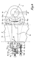
- Fig. 3 is a side view with cutaway, representing a staple established in accordance with the present invention.
- Fig. 4 shows in perspective, prior to their mounting, the different components of the clip according to fig. 3.
- the clip shown in fig. 3 and 4 comprises a main part 15 forming a frame, constituted by a sole against one of the faces of which are attached, by riveting in the embodiment envisaged, on the one hand an eyelet 16 intended to receive the axis for the articulated coupling of the connecting rod 4 of the pulling system associated with the mechanics, on the other hand (in fact in the vicinity of the opposite end of the sole) two protruding guides 17. It will be observed that the eyelet 16 itself has two raised portions 16 has also forming guides, as will be understood better later.
- the frame 15 thus arranged is associated with a slide 18 in the form of a stirrup which opens opposite the eyelet 16; the free ends of the two wings of this slide 18 are joined to each other by a spacer 19 pierced with a central thread inside which is engaged a push screw 20.
- a spacer 19 In a lateral lug 19 a of l the spacer 19 is screwed one of the two opposite threads with a double adjusting screw 21, the other thread cooperating with a thread formed in a lateral lug 17 a from one of the two guides 17 of the frame 15.
- the bottom of the stirrup 18 is equipped with an overhanging corner 22 whose oblique edges cooperate with two profiled jaws 23 which laterally bear against the guides 16 a .
- the guides 17 form supports for two profiled jaws 24 cooperating with a central corner 25.
- a spring 26 is interposed between the ends opposite the corner 25 and the push screw 20 .
- the clip in the assembled state is first engaged on the swingarm 2 intended for him; to do this, just introduce the stirrup 18 on arm 2 which is housed between the two wings of said stirrup, in the portion of it between the central jaw 22 and the two side jaws 24.
- the screw 20 is slightly tightened to transmit to the corner 25, by through the spring 26, and from there to the two jaws 24, a slight pressure.
- the screw 20 acts, by pulling on the stirrup via the spacer 19, on the corner 22 and, from there, on the jaws 23.
- the reduced tightening of screw 20 temporarily prevents sliding of the clip along the arm 2, the slight friction obtained compensating the effect of gravity until complete tightening.
- the operator maneuvers the adjusting screw 21 to move the frame 15, and consequently the eyelet 16 (distance d of fig. 3), relative to the stirrup as a function of the desired height for the heald frame CL .
- the operator tightens the screw 20 to ensure the final blocking of the clip, that is to say on the one hand fix its position along the arm 2 in function of the amplitude of the desired stroke for the heald frame CL considered, and secondly the position of the eyecup 16.
- This double blockage results from the simultaneous action of the ramps of the corners 22 and 25 on the combined ramps of jaws 23 and 24, the screw 20 pushing the wedge central 25 towards the bottom of the stirrup while pulling the corner 22 in the opposite direction.
- each jaw 23 has a beak 23 a , directed towards the opposite jaw 23, at its end opposite to the arm 2.
Landscapes
- Engineering & Computer Science (AREA)
- Textile Engineering (AREA)
- Clamps And Clips (AREA)
- Looms (AREA)
- Paper (AREA)
- Window Of Vehicle (AREA)
- Maintenance And Inspection Apparatuses For Elevators (AREA)
Description
La présente invention a trait aux mécaniques d'armure pour la formation de la foule sur les métiers à tisser et elle concerne plus particulièrement les agrafes réglables qui assurent l'assemblage pivotant des bras oscillants de la mécanique avec les bielles d'attaque du système de tirage associé aux cadres de lisses du métier.The present invention relates to armor mechanics for training of the crowd on the looms and it concerns more particularly the adjustable clips which ensure the pivoting assembly of swing arms of the mechanics with the connecting rods of the system draw associated with heald frames of the trade.
Ainsi qu'on l'a très schématiquement rappelé à la fig. 1 du dessin
annexé aux présentes, une telle agrafe, référencée 1, est susceptible
d'être immobilisée à une position quelconque le long de l'axe de l'un
des bras oscillants 2 (flèche F1) de la mécanique 3, ce qui permet de
régler l'amplitude de la course verticale du cadre de lisses CL qui est
attelé à la bielle d'attaque 4. Par ailleurs le point d'attelage 5 porté
par l'agrafe 1 pour l'articulation de la bielle 4 peut être déplacé
suivant la flèche F2, en autorisant de la sorte le réglage de la hauteur
du cadre CL par rapport au métier à tisser.As has been very schematically recalled in FIG. 1 of the drawing
annexed hereto, such a clip, referenced 1, is likely
to be immobilized at any position along the axis of one
swing arms 2 (arrow F1) of
Le document FR-A-2 398 136 (STAUBLI) montre une agrafe réglable constituée
par une pièce tubulaire 6 (voir fig. 2) formant bâti, qui porte à
l'une de ses extrémités l'axe 5 du point d'attelage. Cette pièce 6 est
découpée d'une échancrure 6a qui est traversée avec un large jeu par le
bras oscillant 2 considéré, lequel est entouré sur trois côtés par le
fond d'un étrier 7 orienté axialement à l'intérieur de la pièce 1 et
mobile dans celle-ci à la manière d'un coulisseau. L'immobilisation de
cet étrier ou coulisseau 7 le long du bras 2 est assurée par un mors 8
commandé par deux rampes latérales opposées 9 elles-mêmes actionnées à
l'aide d'un coin central 10. Ce dernier est associé à une vis de poussée
11 vissée dans le taraudage d'un dé 12 solidaire des extrémités libres
des ailes de l'étrier 7 ; ce dé 12 reçoit l'action d'une vis de réglage
13 à deux filets opposés qui coopère avec une entretoise 14 portée par
l'extrémité de la pièce 6 opposée à celle équipée de l'axe ou point 5.Document FR-A-2 398 136 (STAUBLI) shows an adjustable clip constituted by a tubular piece 6 (see fig. 2) forming a frame, which carries at one of its ends the
On comprend que la vis 13 permet le réglage de la position axiale de la
pièce 6 par rapport au coulisseau ou étrier 7 et, en conséquence, du
point 5 par rapport à la bielle 4, tandis que la manoeuvre de la vis 11
assure l'immobilisation de cette pièce 6 à la hauteur désirée le long du
bras 2.It is understood that the
Il convient toutefois d'observer que les flasques latéraux de la pièce
tubulaire 6 travaillent en porte-à-faux sur la distance PF séparant
l'axe 5 du bord de l'échancrure 6a tourné du côté de l'entretoise 14
alors que sur ces flasques s'exercent des efforts transversaux et axiaux
très importants, induits par l'inclinaison essentiellement variable de
la bielle 4. Comme la disposition côte à côte très rapprochée des bras
oscillants 2 de la mécanique 3 interdit en pratique tout surépaississement
de renfort, les flasques précités parviennent à se rompre et
les performances de la mécanique se trouvent en pratique limitées.It should however be observed that the lateral flanges of the tubular part 6 work in overhang over the distance PF separating the
Dans le but de remédier à cet inconvénient on a proposé, notamment dans les documents EP-A-0 633 335 (STAUBLI) qui représente l'état de la technique le plus proche, et EP-A-0 252 177 (KAISER), de faire comporter au bâti ajouré des mors mobiles de serrage disposés à l'intérieur de l'étrier de part et d'autre du bras et d'agencer le mécanisme de manoeuvre de façon à ce qu'il agisse simultanément sur l'ensemble des mors.In order to remedy this drawback, it has been proposed, in particular in the documents EP-A-0 633 335 (STAUBLI) which represents the closest prior art, and EP-A-0 252 177 (KAISER), of make the perforated frame have movable clamping jaws arranged at inside the stirrup on either side of the arm and arrange the operating mechanism so that it acts simultaneously on the set of jaws.
Si une telle structure permet bien d'éliminer pratiquement tout porte-à-faux dans la fixation de l'agrafe contre le bras oscillant auquel elle est associée, il n'en reste pas moins qu'on se heurte encore à des défauts sensibles, qui tiennent, dans le cas de EP-A-0 633 335 à l'usure causée par le jeu nécessairement prévu entre les pièces constitutives, dans le cas de EP-A-0 252 177 à la complexité et à la fragilité des différents éléments de l'ensemble.If such a structure allows to eliminate practically all overhang in the fastening of the clip against the swinging arm with which it is associated, the fact remains that we still encounter sensitive defects which, in the case of EP-A-0 633 335, are due to the wear and tear caused by the necessarily necessary play between the constituent parts, in the case of EP-A-0 252 177 to the complexity and the fragility of the different elements of the whole.
C'est à ces inconvénients non négligeables qu'entend remédier la
présente invention qui a pour objet l'agrafe réglable qui est définie à
la revendication 1.It is to these non-negligible drawbacks that the
present invention which relates to the adjustable clip which is defined
Le dessin annexé, donné à titre d'exemple, permettra de mieux comprendre l'invention, les caractéristiques qu'elle présente et les avantages qu'elle est susceptible de procurer :The attached drawing, given as an example, will allow a better understanding the invention, the features it presents and the advantages that it is likely to provide:
Comme indiqué plus haut, fig. 1 illustre la fonction d'une agrafe réglable tandis que fig. 2 reflète la technique antérieure révélée par le document FR-A-2 398 136 visé plus haut.As indicated above, fig. 1 illustrates the function of a staple adjustable while fig. 2 reflects the prior art disclosed by the document FR-A-2 398 136 referred to above.
Fig. 3 est une vue de côté avec arrachements, représentant une agrafe établie conformément à la présente invention.Fig. 3 is a side view with cutaway, representing a staple established in accordance with the present invention.
Fig. 4 montre en perspective, préalablement à leur montage, les différents éléments constitutifs de l'agrafe suivant fig. 3. Fig. 4 shows in perspective, prior to their mounting, the different components of the clip according to fig. 3.
L'agrafe représentée en fig. 3 et 4 comprend une pièce principale 15
formant bâti, constituée par une semelle contre l'une des faces de laquelle
sont rapportés, par rivetage dans l'exemple de réalisation envisagé,
d'une part un oeilleton 16 destiné à recevoir l'axe pour l'attelage
articulé de la bielle d'attaque 4 du système de tirage associé à la
mécanique, d'autre part (en fait au voisinage de l'extrémité opposée de
la semelle) deux guides en saillies 17. On observera que l'oeilleton 16
présente lui-même deux parties surélevées 16a formant également guides,
comme on le comprendra mieux plus loin.The clip shown in fig. 3 and 4 comprises a
Au bâti 15 ainsi agencé est associé un coulisseau 18 en forme d'étrier
qui s'ouvre à l'opposé de l'oeilleton 16 ; les extrémités libres des
deux ailes de ce coulisseau 18 sont réunies l'une à l'autre par une
entretoise 19 percée d'un taraudage central à l'intérieur duquel est
engagée une vis de poussée 20. Dans une oreille latérale 19a de l'entretoise
19 est vissé l'un des deux filets opposés d'une vis double de
réglage 21, l'autre filet coopérant avec un taraudage pratiqué dans une
oreille latérale 17a de l'un des deux guides 17 du bâti 15.The
Le fond de l'étrier 18 est équipé d'un coin débordant 22 dont les bords
obliques coopèrent avec deux mors profilés 23 qui prennent latéralement
appui contre les guides 16a. De la même manière, les guides 17 forment
appuis pour deux mors profilés 24 coopérant avec un coin central 25. On
notera qu'un ressort 26 est interposé entre les extrémités en vis-à-vis
du coin 25 et de la vis de poussée 20.The bottom of the
Le fonctionnement comme le mode d'emploi de l'agrafe qui vient d'être décrite découlent des explications qui précédent et se comprennent aisément.The functioning as the user manual of the clip which has just been described flow from the foregoing explanations and are understandable easily.
L'agrafe à l'état monté est en premier lieu engagée sur le bras oscillant
2 qui lui est destiné ; pour cela il suffit d'introduire l'étrier
18 sur le bras 2 qui vient se loger entre les deux ailes dudit étrier,
dans la portion de celui-ci comprise entre le mors central 22 et les
deux mors latéraux 24.The clip in the assembled state is first engaged on the
Puis la vis 20 est légèrement serrée pour transmettre au coin 25, par
l'intermédiaire du ressort 26, et de là aux deux mors 24, une légère
pression. En même temps, la vis 20 agit, par traction sur l'étrier via
l'entretoise 19, sur le coin 22 et, de là, sur les mors 23. Ainsi, le
serrage réduit de la vis 20 évite provisoirement le coulissement de
l'agrafe le long du bras 2, la légère friction obtenue compensant
l'effet de gravité jusqu'au moment du serrage complet.Then the
Puis l'opérateur manoeuvre la vis de réglage 21 pour déplacer le bâti
15, et en conséquence l'oeilleton 16 (distance d de fig. 3), par rapport
à l'étrier en fonction de la hauteur désirée pour le cadre de lisses CL.Then the operator maneuvers the adjusting
Enfin, l'opérateur serre la vis 20 pour assurer le blocage final de
l'agrafe,c'est-à-dire fixer d'une part sa position le long du bras 2 en
fonction de l'amplitude de la course désirée pour le cadre de lisses CL
considéré, et d'autre part la position de l'oeilleton 16. Ce double
blocage résulte de l'action simultanée des rampes des coins 22 et 25 sur
les rampes conjuguées des mors 23 et 24, la vis 20 poussant le coin
central 25 en direction du fond de l'étrier tout en tirant le coin 22
dans le sens opposé.Finally, the operator tightens the
Si finalement ce mode d'emploi est pratiquement identique à celui des
agrafes antérieures suivant fig. 2, on obtient néanmoins une robustesse
bien supérieure, sans que l'encombrement soit sensiblement modifié. Le
serrage opéré de part et d'autre du bras 2 à l'aide des mors 23 et 24
prenant appui contre les guides ou portées 16a et 17 parfaitement
rigides s'oppose à tout fléchissement intempestif, quelles que soient
les sollicitations imparties à l'oeilleton 16 par la bielle 4 lors du
fonctionnement du métier. Tout effet pernicieux de porte-à-faux est du
même coup éliminé, alors que la construction reste simple, ne nécessitant
au surplus aucun jeu susceptible d'engendrer une usure prématurée
des pièces.If finally this manual is practically identical to that of the previous staples according to fig. 2, a much higher robustness is nevertheless obtained, without the space requirement being significantly modified. The operated clamping both sides of the
Il n'est pas sans intérêt d'observer que le guidage du bâti 15 sur le
coulisseau ou étrier 18 est avantageusement amélioré en faisant comporter
d'une part audit bâti une dépression longitudinale référencée 15a en
fig. 4, et d'autre part aux guides 17 une saillie ou talon 17b apte à
s'engager entre les deux ailes dudit étrier.It is not without interest to observe that the guiding of the
On peut noter encore que les mors 23 et 24 présentent avantageusement
des becs d'imperdabilité assurant leur maintien en position quand
l'agrafe n'est pas sur le levier. Ainsi, chaque mors 23 comporte un bec
23a, dirigé vers le mors 23 opposé, à son extrémité opposée au bras 2.
Chaque mors 24, quant à lui, comporte à peu près à mi-longueur, derrière
le coin 25, un bec 24a dirigé vers l'autre mors 24, et également, à son
extrémité opposée au bras 2, un bec 24b dirigé en sens opposé à l'autre
mors 24.It may also be noted that the
On conçoit notamment qu'on peut adopter, pour l'immobilisation de
l'agrafe le long du bras oscillant comme pour le déplacement du bâti par
rapport à l'étrier ou coulisseau, des mécanismes de poussée et de réglage
différents des vis 20 et 21 ci-dessus mentionnées.We understand in particular that we can adopt, for the immobilization of
the clip along the swing arm as for moving the frame by
relation to the stirrup or slide, pushing and adjusting mechanisms
different from the
Claims (9)
- An adjustable clip for the pivoting assembly of the rocking levers (2) of a dobby mechanism (3) with the actuating rods (4) of the lifting system associated with the heald frames (CL) of a loom, of the type comprising a stirrup (18) in the form of a slide which is intended to surround on three sides the rocking lever (2) in question which is engaged with play across the openwork frame (15) of the clip and which is equipped with a manoeuvring mechanism arranged to act on mobile clamping jaws (24) which are arranged on the inside of said stirrup on one side of the lever, in order to ensure firstly the immobilisation of this frame along the lever, and secondly the adjustment in position of this frame perpendicular to the axis of said lever, the frame being provided with two first lateral guides (17) for two jaws (24) which are controlled by means of a first central wedge (25) arranged between the free ends of the wings of said stirrup, whereas the manoeuvring mechanism comprises a screw (20) engaged in an internal thread of a spacer (19) which is fixed between the free ends of the wings of the stirrup (18), characterised in that the frame (15) is provided with two second lateral guides (16a) for two jaws (23) which are arranged on the other side of the lever and are associated with a second manoeuvring wedge (22) engaged in the bottom of the stirrup (18), and in that the screw (20) is arranged to push said first wedge (25) towards the bottom of the stirrup while pulling the second wedge (22) in the opposite direction.
- A clip according to Claim 1, characterised in that between the thrust screw (20) and the central wedge (25) there is interposed an elastic means (26) which acts on said wedge to ensure the temporary retention of the clip along the rocking lever (2) by friction.
- A clip according to any one of Claims 1 and 2, characterised in that the position of the frame (15) relative to the stirrup (18) is adjusted, in a manner known per se, by an adjusting screw (21) having two opposing threads which cooperates with two lateral lugs (17a and 19a) integral respectively with the spacer (19) of the stirrup (18) and the frame (15).
- A clip according to any one of Claims 1 to 3, characterised in that the frame (15) comprises a sole (15) which is integral with one end of an eye (16) provided with two lateral projections (16a) forming said first lateral guides, and at the other end with two other lateral projections (17) forming said second lateral guides.
- A clip according to Claim 4, characterised in that the sole of the frame (15) is provided with a longitudinal depression (15a) forming a guide for the stirrup (18), whereas the projections or guides (17) of this frame have a heel (17b) introduced between the two longitudinal wings of said stirrup.
- A clip according to any one of the preceding claims, characterised in that said second wedge (22) is arranged at the bottom of said stirrup (18).
- A clip according to any one of the preceding claims, characterised in that said second wedge (22) has oblique edges suitable for co-operating with said associated jaws (23).
- A clip according to any one of the preceding claims, characterised in that said screw (20) is suitable for acting by traction on said stirrup (18), on said second wedge (22) and on said associated jaws (23).
- A clip according to any one of the preceding claims, characterised in that said jaws (23, 24) are provided with capturing projections (23a, 24a, 24b).
Applications Claiming Priority (2)
| Application Number | Priority Date | Filing Date | Title |
|---|---|---|---|
| FR9506416A FR2734610B1 (en) | 1995-05-24 | 1995-05-24 | ADJUSTABLE CLIP FOR THE PIVOTING ASSEMBLY OF THE OSCILLATING ARMS OF AN ARMOR MECHANICS WITH THE DRIVING RODS OF THE DRAWING SYSTEM |
| FR9506416 | 1995-05-24 |
Publications (3)
| Publication Number | Publication Date |
|---|---|
| EP0744482A2 EP0744482A2 (en) | 1996-11-27 |
| EP0744482A3 EP0744482A3 (en) | 1998-12-30 |
| EP0744482B1 true EP0744482B1 (en) | 2001-07-11 |
Family
ID=9479509
Family Applications (1)
| Application Number | Title | Priority Date | Filing Date |
|---|---|---|---|
| EP96420188A Expired - Lifetime EP0744482B1 (en) | 1995-05-24 | 1996-05-23 | Adjustable clip to connect the rocking levers of a dobby to the rods of the lifting system |
Country Status (5)
| Country | Link |
|---|---|
| US (1) | US5685346A (en) |
| EP (1) | EP0744482B1 (en) |
| JP (1) | JP3628104B2 (en) |
| DE (1) | DE69613762T2 (en) |
| FR (1) | FR2734610B1 (en) |
Families Citing this family (9)
| Publication number | Priority date | Publication date | Assignee | Title |
|---|---|---|---|---|
| IT1295386B1 (en) * | 1997-10-23 | 1999-05-12 | Fimtextile Spa | DEVICE FOR ADJUSTING THE HEAD OF THE CONTROL TIE-ROD OF LICCI PAINTINGS IN A TEXTILE FRAME |
| FR2776307B1 (en) * | 1998-03-19 | 2000-06-23 | Staubli Sa Ets | DRAWING MECHANISM FOR ARMOR AND WEAVING MECHANISM COMPRISING SUCH A DRAWING MECHANISM |
| FR2836488B1 (en) * | 2002-02-28 | 2004-06-04 | Staubli Sa Ets | DRAWING MECHANISM, MANUFACTURING METHOD THEREOF AND WEAVING MACHINE COMPRISING SUCH A MECHANISM |
| BE1016217A5 (en) * | 2004-09-28 | 2006-05-02 | Wiele Michel Van De Nv | GAAPING DEVICE AND WEAVING MACHINE FITTED WITH SUCH GAAPING DEVICE. |
| US7475708B2 (en) * | 2004-11-17 | 2009-01-13 | Groz-Beckert Kg | Shaft drive for heald shafts of weaving machines |
| FR2913079B1 (en) | 2007-02-22 | 2010-01-01 | Staubli Sa Ets | BEVERAGE BEARING WITH LUBRICATING CAVITY AND WORK DRAWING SYSTEM COMPRISING SUCH A BEARING |
| FR3002546B1 (en) | 2013-02-25 | 2015-08-14 | Staubli Sa Ets | BELT BELONGING TO A WEAVING AND WEAVING BUSINESS INCLUDING THIS ROD |
| FR3126714B1 (en) | 2021-09-06 | 2023-09-08 | Staubli Sa Ets | Shed forming machine for a loom and its adjustment method |
| FR3132108B1 (en) | 2022-01-27 | 2024-01-26 | Staubli Sa Ets | Shed training assembly for a loom and its adjustment process |
Family Cites Families (5)
| Publication number | Priority date | Publication date | Assignee | Title |
|---|---|---|---|---|
| CH621159A5 (en) * | 1977-07-20 | 1981-01-15 | Staeubli Ag | |
| DE3668921D1 (en) * | 1986-07-09 | 1990-03-15 | Kaiser Gmbh & Co Kg | DEVICE FOR CONNECTING A SWINGARM ARM OF A HARNESS TO A SHAFT OF A WEAVING MACHINE. |
| IT1258971B (en) * | 1992-06-11 | 1996-03-11 | Costantino Vinciguerra | ADJUSTABLE CONNECTION TIE-ROD BETWEEN THE DOBBY AND THE SQUARE LEVERS OF THE PANEL CONTROL PANEL OF A TEXTILE FRAME |
| FR2705972B1 (en) * | 1993-06-03 | 1995-07-21 | Staubli Sa Ets | Damping device for weaving machine. |
| EP0633335A1 (en) * | 1993-07-05 | 1995-01-11 | Stäubli AG (Stäubli SA) (Stäubli Ltd.) | Adjusting device in the connecting path between the rocking lever of a dobby and a heald frame of a loom |
-
1995
- 1995-05-24 FR FR9506416A patent/FR2734610B1/en not_active Expired - Fee Related
-
1996
- 1996-05-15 US US08/648,402 patent/US5685346A/en not_active Expired - Fee Related
- 1996-05-21 JP JP12611496A patent/JP3628104B2/en not_active Expired - Lifetime
- 1996-05-23 DE DE69613762T patent/DE69613762T2/en not_active Expired - Lifetime
- 1996-05-23 EP EP96420188A patent/EP0744482B1/en not_active Expired - Lifetime
Also Published As
| Publication number | Publication date |
|---|---|
| JP3628104B2 (en) | 2005-03-09 |
| US5685346A (en) | 1997-11-11 |
| DE69613762T2 (en) | 2002-04-25 |
| DE69613762D1 (en) | 2001-08-16 |
| EP0744482A2 (en) | 1996-11-27 |
| EP0744482A3 (en) | 1998-12-30 |
| FR2734610B1 (en) | 1997-07-04 |
| JPH08325879A (en) | 1996-12-10 |
| FR2734610A1 (en) | 1996-11-29 |
Similar Documents
| Publication | Publication Date | Title |
|---|---|---|
| EP0744482B1 (en) | Adjustable clip to connect the rocking levers of a dobby to the rods of the lifting system | |
| FR2570997A1 (en) | OPENING SUNROOF WHICH LOCKING IS AUTOCOMMENDED WITHOUT ADDITIONAL MECHANISMS | |
| FR2663234A1 (en) | SUPPORT FOR SKI BINDINGS. | |
| EP0297003B1 (en) | Device for coupling heald frames to the transmission elements of a dobby | |
| FR2694681A1 (en) | Alpine ski boot. | |
| EP0117826B1 (en) | Hook-up attachment for the semi-automatic connection of the loom heald frames to their control levers | |
| FR2688822A1 (en) | DEVICE FOR FIXING AN OPERATOR FOR THE OPENING AND CLOSING CONTROL OF A DOOR OR GATE LEAF. | |
| EP0216717B1 (en) | Clamping pliers with self-adjusting jaws | |
| CH616511A5 (en) | Spring hinge for spectacles | |
| FR2466543A1 (en) | DEVICE FOR COUPLING A BLADE DRAWING MEMBER TO A SOFT HOLDER FRAME | |
| FR2548127A1 (en) | DEVICE FOR FASTENING AN ACCESSORY ON A CYCLE | |
| EP0943708A1 (en) | Traction device for shedding mechanisms and loom with such a device | |
| FR2690177A1 (en) | Mechanism locking an instrument on a tractor. | |
| EP0514299A1 (en) | Lever traction device between a Dobby and the weaving frames of a loom | |
| EP0754868B1 (en) | Connection for adjustably assembling two separated elements | |
| FR2642657A1 (en) | SAFETY FASTENING FOR SKI INTENDED TO MAINTAIN THE FRONT OF A SHOE ON A SKI | |
| FR2787283A1 (en) | RETAINER WITH A SPRING FOR AN AGRICULTURAL TOOL, PARTICULARLY A LABORING TOOL | |
| EP0457696B1 (en) | System for joining the traction cables with the traction levers of negative dobbies | |
| BE702816A (en) | ||
| FR2550048A1 (en) | BRABANT OR REVERSIBLE PLOW WITH HITCHING OR SADDLE | |
| FR2642656A1 (en) | SAFETY FASTENING FOR SKI INTENDED TO MAINTAIN THE FRONT OF A SKI SHOE | |
| FR2840267A1 (en) | Vehicle seat comprises seat part and back having lower and upper pivoted parts connected by locking mechanism belonging to bi-stable mechanical device comprising pusher which can push back upper part onto folded down position | |
| EP0491412A1 (en) | Fixation device for an element in a frame | |
| BE438253A (en) | ||
| FR2718254A1 (en) | Lens retainer for spectacle frame |
Legal Events
| Date | Code | Title | Description |
|---|---|---|---|
| PUAI | Public reference made under article 153(3) epc to a published international application that has entered the european phase |
Free format text: ORIGINAL CODE: 0009012 |
|
| AK | Designated contracting states |
Kind code of ref document: A2 Designated state(s): BE CH DE FR GB IT LI |
|
| PUAL | Search report despatched |
Free format text: ORIGINAL CODE: 0009013 |
|
| AK | Designated contracting states |
Kind code of ref document: A3 Designated state(s): BE CH DE FR GB IT LI |
|
| ITCL | It: translation for ep claims filed |
Representative=s name: MODIANO & ASSOCIATI S.R.L. |
|
| 17P | Request for examination filed |
Effective date: 19990505 |
|
| GRAG | Despatch of communication of intention to grant |
Free format text: ORIGINAL CODE: EPIDOS AGRA |
|
| GRAG | Despatch of communication of intention to grant |
Free format text: ORIGINAL CODE: EPIDOS AGRA |
|
| 17Q | First examination report despatched |
Effective date: 19990818 |
|
| GRAG | Despatch of communication of intention to grant |
Free format text: ORIGINAL CODE: EPIDOS AGRA |
|
| GRAH | Despatch of communication of intention to grant a patent |
Free format text: ORIGINAL CODE: EPIDOS IGRA |
|
| GRAH | Despatch of communication of intention to grant a patent |
Free format text: ORIGINAL CODE: EPIDOS IGRA |
|
| GRAA | (expected) grant |
Free format text: ORIGINAL CODE: 0009210 |
|
| AK | Designated contracting states |
Kind code of ref document: B1 Designated state(s): BE CH DE FR GB IT LI |
|
| REG | Reference to a national code |
Ref country code: CH Ref legal event code: EP |
|
| REF | Corresponds to: |
Ref document number: 69613762 Country of ref document: DE Date of ref document: 20010816 |
|
| GBT | Gb: translation of ep patent filed (gb section 77(6)(a)/1977) |
Effective date: 20010831 |
|
| ITF | It: translation for a ep patent filed | ||
| REG | Reference to a national code |
Ref country code: GB Ref legal event code: IF02 |
|
| PLBE | No opposition filed within time limit |
Free format text: ORIGINAL CODE: 0009261 |
|
| STAA | Information on the status of an ep patent application or granted ep patent |
Free format text: STATUS: NO OPPOSITION FILED WITHIN TIME LIMIT |
|
| 26N | No opposition filed | ||
| PGFP | Annual fee paid to national office [announced via postgrant information from national office to epo] |
Ref country code: GB Payment date: 20040518 Year of fee payment: 9 |
|
| PG25 | Lapsed in a contracting state [announced via postgrant information from national office to epo] |
Ref country code: GB Free format text: LAPSE BECAUSE OF NON-PAYMENT OF DUE FEES Effective date: 20050523 |
|
| GBPC | Gb: european patent ceased through non-payment of renewal fee |
Effective date: 20050523 |
|
| PGFP | Annual fee paid to national office [announced via postgrant information from national office to epo] |
Ref country code: CH Payment date: 20080515 Year of fee payment: 13 |
|
| REG | Reference to a national code |
Ref country code: CH Ref legal event code: PL |
|
| PG25 | Lapsed in a contracting state [announced via postgrant information from national office to epo] |
Ref country code: LI Free format text: LAPSE BECAUSE OF NON-PAYMENT OF DUE FEES Effective date: 20090531 Ref country code: CH Free format text: LAPSE BECAUSE OF NON-PAYMENT OF DUE FEES Effective date: 20090531 |
|
| REG | Reference to a national code |
Ref country code: FR Ref legal event code: ST Effective date: 20100129 |
|
| PG25 | Lapsed in a contracting state [announced via postgrant information from national office to epo] |
Ref country code: FR Free format text: LAPSE BECAUSE OF NON-PAYMENT OF DUE FEES Effective date: 20090602 |
|
| PGFP | Annual fee paid to national office [announced via postgrant information from national office to epo] |
Ref country code: FR Payment date: 20080429 Year of fee payment: 13 |
|
| PGFP | Annual fee paid to national office [announced via postgrant information from national office to epo] |
Ref country code: DE Payment date: 20140509 Year of fee payment: 19 Ref country code: IT Payment date: 20140513 Year of fee payment: 19 |
|
| PGFP | Annual fee paid to national office [announced via postgrant information from national office to epo] |
Ref country code: BE Payment date: 20140527 Year of fee payment: 19 |
|
| REG | Reference to a national code |
Ref country code: DE Ref legal event code: R119 Ref document number: 69613762 Country of ref document: DE |
|
| PG25 | Lapsed in a contracting state [announced via postgrant information from national office to epo] |
Ref country code: IT Free format text: LAPSE BECAUSE OF NON-PAYMENT OF DUE FEES Effective date: 20150523 |
|
| PG25 | Lapsed in a contracting state [announced via postgrant information from national office to epo] |
Ref country code: DE Free format text: LAPSE BECAUSE OF NON-PAYMENT OF DUE FEES Effective date: 20151201 |
|
| PG25 | Lapsed in a contracting state [announced via postgrant information from national office to epo] |
Ref country code: BE Free format text: LAPSE BECAUSE OF NON-PAYMENT OF DUE FEES Effective date: 20150531 |