EP0744235A2 - Plandrehwerkzeug für Rohre - Google Patents
Plandrehwerkzeug für Rohre Download PDFInfo
- Publication number
- EP0744235A2 EP0744235A2 EP96103254A EP96103254A EP0744235A2 EP 0744235 A2 EP0744235 A2 EP 0744235A2 EP 96103254 A EP96103254 A EP 96103254A EP 96103254 A EP96103254 A EP 96103254A EP 0744235 A2 EP0744235 A2 EP 0744235A2
- Authority
- EP
- European Patent Office
- Prior art keywords
- cutter
- tube
- side face
- drive shaft
- reference side
- Prior art date
- Legal status (The legal status is an assumption and is not a legal conclusion. Google has not performed a legal analysis and makes no representation as to the accuracy of the status listed.)
- Granted
Links
Images



Classifications
-
- B—PERFORMING OPERATIONS; TRANSPORTING
- B23—MACHINE TOOLS; METAL-WORKING NOT OTHERWISE PROVIDED FOR
- B23C—MILLING
- B23C3/00—Milling particular work; Special milling operations; Machines therefor
- B23C3/12—Trimming or finishing edges, e.g. deburring welded corners
-
- B—PERFORMING OPERATIONS; TRANSPORTING
- B23—MACHINE TOOLS; METAL-WORKING NOT OTHERWISE PROVIDED FOR
- B23B—TURNING; BORING
- B23B5/00—Turning-machines or devices specially adapted for particular work; Accessories specially adapted therefor
- B23B5/16—Turning-machines or devices specially adapted for particular work; Accessories specially adapted therefor for bevelling, chamfering, or deburring the ends of bars or tubes
- B23B5/161—Devices attached to the workpiece
- B23B5/163—Devices attached to the workpiece with an external clamping device
-
- Y—GENERAL TAGGING OF NEW TECHNOLOGICAL DEVELOPMENTS; GENERAL TAGGING OF CROSS-SECTIONAL TECHNOLOGIES SPANNING OVER SEVERAL SECTIONS OF THE IPC; TECHNICAL SUBJECTS COVERED BY FORMER USPC CROSS-REFERENCE ART COLLECTIONS [XRACs] AND DIGESTS
- Y10—TECHNICAL SUBJECTS COVERED BY FORMER USPC
- Y10T—TECHNICAL SUBJECTS COVERED BY FORMER US CLASSIFICATION
- Y10T408/00—Cutting by use of rotating axially moving tool
- Y10T408/55—Cutting by use of rotating axially moving tool with work-engaging structure other than Tool or tool-support
- Y10T408/563—Work-gripping clamp
- Y10T408/5633—Adapted to coaxially grip round work
-
- Y—GENERAL TAGGING OF NEW TECHNOLOGICAL DEVELOPMENTS; GENERAL TAGGING OF CROSS-SECTIONAL TECHNOLOGIES SPANNING OVER SEVERAL SECTIONS OF THE IPC; TECHNICAL SUBJECTS COVERED BY FORMER USPC CROSS-REFERENCE ART COLLECTIONS [XRACs] AND DIGESTS
- Y10—TECHNICAL SUBJECTS COVERED BY FORMER USPC
- Y10T—TECHNICAL SUBJECTS COVERED BY FORMER US CLASSIFICATION
- Y10T82/00—Turning
- Y10T82/22—Portable lathe for pipe turning
Definitions
- the present invention relates to a tube facing machine for facing cut ends of tubes at right angles with the axis of the tube to facilitate the subsequent treatment such as welding.
- FIGS. 7 and 8 show a tube facing machine already known for squaring ends of tubes for facilitated welding (see U.S.P. No. 4,319,503).
- the tube facing machine comprises a hollow cylindrical body 1 extending longitudinally of the machine, a sleeve 2 slidably disposed inside the body 1, a sleeve sliding side handle 3 provided on the outer side of the body 1, a cutter rotating drive shaft 4 rotatably supported by the sleeve 3 inside thereof, a cutter 11 attached to the front end of the drive shaft 4 for cutting the rear end of a tube T to be faced, a cam 5 in engagement with the sleeve 2 for converting the rotation of the side handle 3 to a sliding movement of the sleeve 2, a fixed ring 6 projecting forward from the front end of the body 1 and having a rearwardly tapered inner periphery 6a, a collet 7 inserted in the fixed ring 6 for holding the tube T so that the axis of the
- a solid cylindrical cutter mount 9 coaxial with, and having a larger diameter than, the shaft.
- a rectangular parallelepipedal base end portion 12 of the cutter 11 is fitted in a cutter mount groove 10 formed in the front end of the cutter mount 9.
- the cutter 11 has a prismatic portion 11a extending forward from the base end portion 12.
- the prismatic portion 11a is formed at its front end with a cutting edge 13 at right angles with the axis 15 of the drive shaft 4.
- the cutter mount groove 10 extends approximately diametrically of the mount 9 and is defined by a reference side face 10a containing the axis 15 of the drive shaft 4 and an opposed side face 10b parallel to the side face 10a.
- the base end portion 12 of the cutter 11 has a reference side face 12a bearing on the groove-defining reference side face 10a and pressed against the side face 10a by screws 14 driven into the side portion of the mount 9 having the opposed side face 10b.
- the cutting edge 13 of the cutter 11 is positioned radially of the tube T, and the cutter 11 is rotated counterclockwise in the drawing.
- the conventional tube facing machine described has the problem that chips enter the tube during cutting, rotating in the interior of the tube with the rotation of the cutter to deface the tube inner surface. If the tube is internally defaced, dirt will accumulate therein or impaired corrosion resistance will result. The result is especially serious in the case of tubes of small diameter, such as tubes for use in preparing semiconductors, which must retain extreme cleanliness.
- An object of the present invention is to provide a tube facing machine which is unlikely to internally deface tubes.
- the present invention provides a tube facing machine which comprises a hollow cylindrical body extending longitudinally of the machine, a cutter rotating drive shaft disposed inside the body, a cutter attached to a front end portion of the drive shaft for facing an end of a tube, means for holding the tube in front of the cutter so as to align the axis of the tube with the axis of the drive shaft, and means for moving the drive shaft longitudinally of the machine, the tube facing machine being characterized in that the cutter is so fixed that the cutting direction thereof is a pre-determined angle outward with respect to a tangential direction of the tube at the position of cutting.
- the cutter is so fixed that the cutting direction thereof is a predetermined angle outward with respect to a tangential direction at the cutting position.
- the chips produced by cutting, i.e., facing, are therefore sent outward without entering the tube, and the burrs projecting from the tube inner periphery are small. Being sent outward without ingressing into the tube, the chips are unlikely to deface the tube inner periphery. Further because the burrs projecting from the tube inner periphery are diminished, the interior of the tube is kept very clean.
- the angle the cutter cutting direction makes with the tangential direction at the cutting position is preferably 10 to 40 degrees, more preferably 20 to 30 degrees. If this angle is smaller, chips are likely to enter the tube, whereas larger angles impair the life of the cutter.
- the front end portion of the drive shaft is formed with a cutter mount groove defined by a reference side face
- the cutter is formed on a base end portion thereof with a reference side face bearing on the groove-defining reference side face
- a cutting edge is formed at a front end of the cutter.
- the cutting edge extends from a plane containing the reference side face of the cutter base end portion, and the groove-defining reference side face is positioned a specified distance away from the axis of the drive shaft.
- the range in which the angle between the cutter cutting direction and the tangential direction at the cutting position is adjustable is then determined by adjusting the distance of the reference side face defining the cutter mount groove from the axis of the drive shaft, and the angle is finely adjusted by moving the cutter longitudinally of the mount groove with the cutter base end portion in bearing contact with the groove-defining reference side face. Because the adjustable angular range is thus determinable by adjusting the above-mentioned distance and because the angle is finely adjustable by moving the cutter in this way, the cutting direction of the cutter can be readily made outward by a specified angle even when tubes of small diameter are to be cut for facing.
- front and rear are herein used based on FIG. 1; the right-hand side of the drawing is referred to as “front,” and the left-hand side thereof as “rear.”
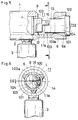
- the machine comprises a hollow cylindrical body 1 extending longitudinally of the machine, a sleeve 2 slidably disposed inside the body 1, a sleeve sliding side handle 3 provided on the outer side of the body 1, a cutter rotating drive shaft 4 rotatably supported by the sleeve 3 inside thereof, a cutter 11 attached to the front end of the drive shaft 4 for cutting the rear end of a tube T to be faced, a cam 5 in engagement with the sleeve 2 for converting the rotation of the slide handle 3 to a sliding movement of the sleeve 2, a fixed ring 6 projecting forward from the front end of the body 1 and having a rearwardly tapered inner periphery 6a, a collet 7 inserted in the fixed ring 6 for holding the tube T so that the axis of the tube T is aligned with the axis 15 of the drive shaft 4, and a collet fastening ring 8.
- a solid cylindrical cutter mount 9 coaxial with the shaft and having a larger diameter than the shaft.
- a rectangular parallelepipedal base end portion 12 of the cutter 11 is fitted in a cutter mount groove 100 formed in the front end of the cutter mount 9.
- the cutter 11 has a prismatic portion 11a extending forward from the base end portion 12 and is L-shaped when seen from one side and rectangular when seen from the front.
- the prismatic portion 11a has a front end face perpendicular to the axis 15 of the drive shaft 4.
- a cutting face 16 approximately triangular when seen from the front is formed in the front end part of the prismatic portion 11a, whereby a cutting edge 13 is formed at the front end of the prismatic portion 11a, the cutting edge 13 being at right angles with the axis 15 of the drive shaft 4 and extending obliquely from a plane containing a reference side face 12a of the base end portion 12.
- the cutter mount groove 100 extends approximately diametrically of the cutter mount 9 and is defined by a reference side face 100a and an opposed side face 100b parallel to the face 100a.
- the base end portion 12 of the cutter 11 is fixedly pressed against the groove-defining reference side face 100a by screws 14 driven into the side portion of the mount 9 having the opposed side face 100b, with the reference side face 12a bearing on the reference side face 100a.
- the cutter 11 is rotated counterclockwise in FIG. 2.
- the cutter mount groove 100 of the tube facing machine of the invention differs in shape from the groove 10 of the conventional machine. Stated more specifically with reference to FIG. 8, the reference side face 10a of the conventional cutter mount groove 10 contains the axis 15 of the drive shaft 4, whereas the groove 100 of the present machine is so shaped that the axis 15 of the drive shaft 4 is positioned between the reference side face 100a and the opposed side face 100b as shown in FIG. 3.
- the cutter mount groove 100 can be readily formed by cutting the reference side face 10a of the conventional cutter mount groove 10 by a specified distance D1.
- the cutting edge 13 of the cutter 11 extends radially of the tube T, and chips are sent in a tangential direction B3 of the tube T and are therefore very likely to enter the tube T, while large burrs project from the inner periphery of the tube T.
- the chips rotate with the rotation of the cutter 11 in the interior of the tube T, giving rise to the problem of internally defacing the tube.
- the cutter 11 is mounted as shifted by the specified distance D1 from the axis 15 of the drive shaft 4, with the result that the cutting edge 13 of the cutter 11 is not in coincidence with a radial direction of the tube T but intersects the radial direction at an angle C1. More specifically, the cutting direction A1 of the cutting edge 13 is an angle C1 outward with respect to a tangential direction B1 of the tube T at the cutting position. Accordingly, the chips are sent outward without entering the tube T, while the burrs projecting from the inner periphery of the tube T are small. The small burrs projecting from the inner periphery melt during welding and therefore need not be removed. Although slightly larger burrs than conventionally project from the tube outer periphery, these burrs pose no problem since they are formed on the outer periphery.
- the cutting edge 13 may be positioned as projected beyond the reference side face 10a defining the conventional cutter mount groove 10 by cutting the reference side face 12a of the base end portion 12 of the cutter 11 instead of cutting the reference side face 10a by the specified distance D1.
- the angle C1 the cutting direction A1 of the cutting edge 13 makes with the tangential direction B1 of the tube T at the cutting position varies with the distance D1 of the reference side face 100a defining the mount groove 100 from the axis 15 of the drive shaft 4
- the angle C1 is preferably 10 to 40 degrees, more preferably 20 to 30 degrees, most preferably about 25 degrees. If the angle C1 is smaller, there is the possibility of the chips entering the tube T, whereas larger angles impair the life the cutter 11.
- the angle C2 the cutting direction A2 of the cutting edge 13 makes with a tangential direction B2 of the tube T at the cutting position is slightly variable by moving the cutter 11 a distance D2 longitudinally of the cutter mount groove 100. In FIG.
- the cutting direction A2 of the cutting edge 13 is an angle C2 outward with respect to the tangential direction B2 of the tube T at the cutting position, and this arrangement achieves the same effect as that shown in FIG. 3.
- the most preferable angle is available by so adjusting the distance D2 of movement that the angle C2 becomes 25 degrees.
- the range in which the angle C1 or C2 between the cutting direction of the cutter 11 and the tangential direction at the cutting position is adjustable is determined by the distance D1 of the reference side face 100a defining the mount groove 100 from the axis 15 of the drive shaft 4, and the angle is further finely adjusted by moving the cutter 11 longitudinally of the mount groove 100.
- FIGS. 5 and 6 show a cutter positioning jig 101 for use in moving the cutter 11 longitudinally of the cutter mount groove 100.
- the jig 101 is in the form of a solid cylinder of polyacetal resin having an outside diameter equal to the inside diameter of the fixed ring 6.
- the jig has at its front end a flange 102 having a slightly smaller diameter than the tapered inner periphery 6a of the fixed ring 6.
- An approximate half of a solid cylinder slightly smaller than a perfect half thereof is removed from the rear end portion of the jig.
- the remaining, approximately half solid cylinder portion 103 has a rectangular side surface 103a parallel to the axis 104 of the jig 101 and away from the axis 104 by the specified distance D2.
- the axis 104 of the jig 101 is aligned with the axis 15 of the drive shaft 4, whereby the cutter 11 can be moved longitudinally of the mount groove 100 by the specified distance D2 from the axis 15 of the drive shaft 4.
- the use of the jig 101 makes it possible to position the cutting edge 13 as shown in FIG. 4, as shifted by D2 along the length of the groove 100 from the reference position of the drive shaft axis 15.
Landscapes
- Engineering & Computer Science (AREA)
- Mechanical Engineering (AREA)
- Turning (AREA)
- Dry Shavers And Clippers (AREA)
- Nonmetal Cutting Devices (AREA)
Applications Claiming Priority (3)
| Application Number | Priority Date | Filing Date | Title |
|---|---|---|---|
| JP96423/95 | 1995-04-21 | ||
| JP9642395 | 1995-04-21 | ||
| JP09642395A JP3413541B2 (ja) | 1995-04-21 | 1995-04-21 | チューブ端面削り機 |
Publications (3)
| Publication Number | Publication Date |
|---|---|
| EP0744235A2 true EP0744235A2 (de) | 1996-11-27 |
| EP0744235A3 EP0744235A3 (de) | 1997-02-26 |
| EP0744235B1 EP0744235B1 (de) | 2001-05-02 |
Family
ID=14164583
Family Applications (1)
| Application Number | Title | Priority Date | Filing Date |
|---|---|---|---|
| EP96103254A Expired - Lifetime EP0744235B1 (de) | 1995-04-21 | 1996-03-02 | Plandrehwerkzeug für Rohre |
Country Status (7)
| Country | Link |
|---|---|
| US (1) | US5711197A (de) |
| EP (1) | EP0744235B1 (de) |
| JP (1) | JP3413541B2 (de) |
| KR (1) | KR100391228B1 (de) |
| CA (1) | CA2172360A1 (de) |
| DE (1) | DE69612639T2 (de) |
| TW (1) | TW276202B (de) |
Families Citing this family (11)
| Publication number | Priority date | Publication date | Assignee | Title |
|---|---|---|---|---|
| US6279437B1 (en) | 1998-05-26 | 2001-08-28 | Climax Portable Machine Tools, Inc. | Pipe beveling machine |
| US6460438B2 (en) | 1998-07-10 | 2002-10-08 | Swagelok Company | Facing tool |
| US6186037B1 (en) * | 1999-06-25 | 2001-02-13 | Donato L. Ricci | Tube squaring machine having axially stationary cutting tool shaft and axially movable tube holding collet |
| USD427499S (en) * | 1999-11-22 | 2000-07-04 | Donato L. Ricci | Tube squaring machine |
| US6412376B1 (en) * | 2000-05-12 | 2002-07-02 | Joseph Borgia, Jr. | PVC pipe end smooth surfacer |
| JP2002187094A (ja) * | 2000-12-19 | 2002-07-02 | Toho Kasei Kk | 樹脂製チューブの端面カッター及びこれを用いた樹脂製チューブの端面カット方法 |
| US6755101B1 (en) | 2003-05-29 | 2004-06-29 | Babcock & Wilcox Canada Ltd. | Low profile in-line beveler |
| US20080003069A1 (en) * | 2006-06-16 | 2008-01-03 | Harper David J | Apparatus and method for removing inner member of plastic pipe joint |
| KR101686187B1 (ko) | 2015-08-07 | 2016-12-13 | 주식회사 쏠락 | 튜브 단부 절삭장치 |
| KR102056764B1 (ko) * | 2019-06-28 | 2020-01-22 | 디씨에스이엔지 주식회사 | 튜브 내부로 절삭 칩의 유입을 방지하는 페이싱 머신 |
| RU198099U1 (ru) * | 2020-03-20 | 2020-06-17 | федеральное государственное бюджетное образовательное учреждение высшего образования «Вологодская государственная молочнохозяйственная академия имени Н.В. Верещагина» (ФГБОУ ВО Вологодская ГМХА) | Приспособление для обработки посадочной поверхности под буртик гильзы в блоке цилиндров |
Family Cites Families (7)
| Publication number | Priority date | Publication date | Assignee | Title |
|---|---|---|---|---|
| US3848489A (en) * | 1973-03-09 | 1974-11-19 | A Santana | Rotary machine tool |
| US3868752A (en) * | 1973-11-16 | 1975-03-04 | Valeron Corp | Cutting tool |
| US4114484A (en) * | 1976-11-16 | 1978-09-19 | Feamster Iii William C | Pipe cutting or end prepping apparatus |
| US4319503A (en) | 1980-06-26 | 1982-03-16 | Tri Tool Inc. | Tube facing machine |
| DE3215385A1 (de) * | 1982-04-24 | 1983-11-03 | Dr. techn. Ernst Linsinger & Co GmbH, 4662 Steyrermühl | Verfahren und vorrichtung zum trennen insbesondere langer werkstuecke |
| US5351587A (en) * | 1990-05-21 | 1994-10-04 | Rodney Griffin | Cutting tool for machining a plumbing nipple |
| US5393176A (en) * | 1994-01-26 | 1995-02-28 | The Babcock & Wilcox Company | Tube bevelling machine with adjustable bevelling head |
-
1995
- 1995-04-21 JP JP09642395A patent/JP3413541B2/ja not_active Expired - Fee Related
- 1995-10-24 TW TW084111228A patent/TW276202B/zh active
- 1995-10-31 KR KR1019950038550A patent/KR100391228B1/ko not_active Expired - Fee Related
-
1996
- 1996-03-02 DE DE69612639T patent/DE69612639T2/de not_active Expired - Lifetime
- 1996-03-02 EP EP96103254A patent/EP0744235B1/de not_active Expired - Lifetime
- 1996-03-21 CA CA002172360A patent/CA2172360A1/en not_active Abandoned
- 1996-04-04 US US08/627,549 patent/US5711197A/en not_active Expired - Fee Related
Also Published As
| Publication number | Publication date |
|---|---|
| JPH08290301A (ja) | 1996-11-05 |
| DE69612639T2 (de) | 2001-09-20 |
| US5711197A (en) | 1998-01-27 |
| KR100391228B1 (ko) | 2003-11-14 |
| KR960037187A (ko) | 1996-11-19 |
| CA2172360A1 (en) | 1996-10-22 |
| JP3413541B2 (ja) | 2003-06-03 |
| DE69612639D1 (de) | 2001-06-07 |
| EP0744235B1 (de) | 2001-05-02 |
| EP0744235A3 (de) | 1997-02-26 |
| TW276202B (en) | 1996-05-21 |
Similar Documents
| Publication | Publication Date | Title |
|---|---|---|
| EP0744235B1 (de) | Plandrehwerkzeug für Rohre | |
| US6722668B2 (en) | Chuck having quick change mechanism | |
| US6565227B1 (en) | Method and device for tool alignment | |
| EP1234633B1 (de) | Hochgenaue Bohrerschleifvorrichtung und Schleifscheibenaufbau dazu | |
| EP1658152B1 (de) | Zubehörbefestigung für Drehhandwerkzeuge | |
| US4364290A (en) | Adjustable tool holder | |
| JP2003266221A (ja) | 自己付着ドリル | |
| JP2000254820A (ja) | 動力工具、鋸刃、駆動機構部、誤装着防止機構、誤装着判断方法 | |
| EP0883459B1 (de) | Schlüssellose sägeblatteinspannvorrichtung | |
| CN1633344A (zh) | 用于刀具的防错方法和设备 | |
| US7089838B2 (en) | Zero centerline toolholder assembly | |
| EP0933156A2 (de) | Futter mit Stop für die Spannbacken | |
| US6505840B2 (en) | Quick change chuck | |
| JP2003225819A (ja) | ホールソー | |
| US4582332A (en) | Spring chuck | |
| JP2003054193A (ja) | 塗膜転写具 | |
| US12157174B2 (en) | Facing machine for preventing inflow of cutting chips into tube | |
| GB2352661A (en) | Disc driven chuck | |
| JP2000158223A (ja) | 管状部材の端部加工装置における加工屑の侵入阻止方法 | |
| JP3890439B2 (ja) | 光ファイバ端面の加工装置 | |
| EP1737599B1 (de) | System aus einem rotierenden handwerkzeug und einem anschlusszubehör | |
| JP3944593B2 (ja) | 光ファイバ端面の加工装置 | |
| JPH0915480A (ja) | 補助レンズ系切り換え機構を有したレンズ鏡筒 | |
| JP2662926B2 (ja) | 丸鋸等の薄肉円形刃の着脱用治具 | |
| JP4535545B2 (ja) | 穴明け加工機械 |
Legal Events
| Date | Code | Title | Description |
|---|---|---|---|
| PUAI | Public reference made under article 153(3) epc to a published international application that has entered the european phase |
Free format text: ORIGINAL CODE: 0009012 |
|
| AK | Designated contracting states |
Kind code of ref document: A2 Designated state(s): DE FR GB IT NL |
|
| PUAL | Search report despatched |
Free format text: ORIGINAL CODE: 0009013 |
|
| AK | Designated contracting states |
Kind code of ref document: A3 Designated state(s): DE FR GB IT NL |
|
| 17P | Request for examination filed |
Effective date: 19970621 |
|
| 17Q | First examination report despatched |
Effective date: 19990527 |
|
| GRAG | Despatch of communication of intention to grant |
Free format text: ORIGINAL CODE: EPIDOS AGRA |
|
| GRAG | Despatch of communication of intention to grant |
Free format text: ORIGINAL CODE: EPIDOS AGRA |
|
| GRAH | Despatch of communication of intention to grant a patent |
Free format text: ORIGINAL CODE: EPIDOS IGRA |
|
| GRAH | Despatch of communication of intention to grant a patent |
Free format text: ORIGINAL CODE: EPIDOS IGRA |
|
| GRAA | (expected) grant |
Free format text: ORIGINAL CODE: 0009210 |
|
| AK | Designated contracting states |
Kind code of ref document: B1 Designated state(s): DE FR GB IT NL |
|
| ITF | It: translation for a ep patent filed | ||
| REF | Corresponds to: |
Ref document number: 69612639 Country of ref document: DE Date of ref document: 20010607 |
|
| ET | Fr: translation filed | ||
| REG | Reference to a national code |
Ref country code: GB Ref legal event code: IF02 |
|
| PLBE | No opposition filed within time limit |
Free format text: ORIGINAL CODE: 0009261 |
|
| STAA | Information on the status of an ep patent application or granted ep patent |
Free format text: STATUS: NO OPPOSITION FILED WITHIN TIME LIMIT |
|
| 26N | No opposition filed | ||
| PGFP | Annual fee paid to national office [announced via postgrant information from national office to epo] |
Ref country code: GB Payment date: 20040212 Year of fee payment: 9 |
|
| PGFP | Annual fee paid to national office [announced via postgrant information from national office to epo] |
Ref country code: DE Payment date: 20040213 Year of fee payment: 9 |
|
| PGFP | Annual fee paid to national office [announced via postgrant information from national office to epo] |
Ref country code: NL Payment date: 20040317 Year of fee payment: 9 |
|
| PGFP | Annual fee paid to national office [announced via postgrant information from national office to epo] |
Ref country code: FR Payment date: 20040318 Year of fee payment: 9 |
|
| PG25 | Lapsed in a contracting state [announced via postgrant information from national office to epo] |
Ref country code: DE Free format text: LAPSE BECAUSE OF THE APPLICANT RENOUNCES Effective date: 20050215 |
|
| PG25 | Lapsed in a contracting state [announced via postgrant information from national office to epo] |
Ref country code: IT Free format text: LAPSE BECAUSE OF NON-PAYMENT OF DUE FEES Effective date: 20050302 Ref country code: GB Free format text: LAPSE BECAUSE OF NON-PAYMENT OF DUE FEES Effective date: 20050302 |
|
| PG25 | Lapsed in a contracting state [announced via postgrant information from national office to epo] |
Ref country code: NL Free format text: LAPSE BECAUSE OF NON-PAYMENT OF DUE FEES Effective date: 20051001 |
|
| GBPC | Gb: european patent ceased through non-payment of renewal fee |
Effective date: 20050302 |
|
| PG25 | Lapsed in a contracting state [announced via postgrant information from national office to epo] |
Ref country code: FR Free format text: LAPSE BECAUSE OF NON-PAYMENT OF DUE FEES Effective date: 20051130 |
|
| NLV4 | Nl: lapsed or anulled due to non-payment of the annual fee |
Effective date: 20051001 |
|
| REG | Reference to a national code |
Ref country code: FR Ref legal event code: ST Effective date: 20051130 |