EP0743788A1 - Convertisseur automatique de format de balayage d'image avec commutation sans joint - Google Patents
Convertisseur automatique de format de balayage d'image avec commutation sans joint Download PDFInfo
- Publication number
- EP0743788A1 EP0743788A1 EP96107507A EP96107507A EP0743788A1 EP 0743788 A1 EP0743788 A1 EP 0743788A1 EP 96107507 A EP96107507 A EP 96107507A EP 96107507 A EP96107507 A EP 96107507A EP 0743788 A1 EP0743788 A1 EP 0743788A1
- Authority
- EP
- European Patent Office
- Prior art keywords
- format
- signal
- path
- interlaced
- input
- Prior art date
- Legal status (The legal status is an assumption and is not a legal conclusion. Google has not performed a legal analysis and makes no representation as to the accuracy of the status listed.)
- Granted
Links
Images


Classifications
-
- H—ELECTRICITY
- H04—ELECTRIC COMMUNICATION TECHNIQUE
- H04N—PICTORIAL COMMUNICATION, e.g. TELEVISION
- H04N7/00—Television systems
- H04N7/01—Conversion of standards, e.g. involving analogue television standards or digital television standards processed at pixel level
- H04N7/0117—Conversion of standards, e.g. involving analogue television standards or digital television standards processed at pixel level involving conversion of the spatial resolution of the incoming video signal
- H04N7/012—Conversion between an interlaced and a progressive signal
-
- H—ELECTRICITY
- H04—ELECTRIC COMMUNICATION TECHNIQUE
- H04N—PICTORIAL COMMUNICATION, e.g. TELEVISION
- H04N21/00—Selective content distribution, e.g. interactive television or video on demand [VOD]
- H04N21/40—Client devices specifically adapted for the reception of or interaction with content, e.g. set-top-box [STB]; Operations thereof
- H04N21/41—Structure of client; Structure of client peripherals
- H04N21/426—Internal components of the client ; Characteristics thereof
-
- H—ELECTRICITY
- H04—ELECTRIC COMMUNICATION TECHNIQUE
- H04N—PICTORIAL COMMUNICATION, e.g. TELEVISION
- H04N7/00—Television systems
- H04N7/01—Conversion of standards, e.g. involving analogue television standards or digital television standards processed at pixel level
-
- H—ELECTRICITY
- H04—ELECTRIC COMMUNICATION TECHNIQUE
- H04N—PICTORIAL COMMUNICATION, e.g. TELEVISION
- H04N21/00—Selective content distribution, e.g. interactive television or video on demand [VOD]
- H04N21/20—Servers specifically adapted for the distribution of content, e.g. VOD servers; Operations thereof
- H04N21/23—Processing of content or additional data; Elementary server operations; Server middleware
- H04N21/234—Processing of video elementary streams, e.g. splicing of video streams, manipulating MPEG-4 scene graphs
- H04N21/2343—Processing of video elementary streams, e.g. splicing of video streams, manipulating MPEG-4 scene graphs involving reformatting operations of video signals for distribution or compliance with end-user requests or end-user device requirements
- H04N21/234309—Processing of video elementary streams, e.g. splicing of video streams, manipulating MPEG-4 scene graphs involving reformatting operations of video signals for distribution or compliance with end-user requests or end-user device requirements by transcoding between formats or standards, e.g. from MPEG-2 to MPEG-4 or from Quicktime to Realvideo
-
- H—ELECTRICITY
- H04—ELECTRIC COMMUNICATION TECHNIQUE
- H04N—PICTORIAL COMMUNICATION, e.g. TELEVISION
- H04N21/00—Selective content distribution, e.g. interactive television or video on demand [VOD]
- H04N21/20—Servers specifically adapted for the distribution of content, e.g. VOD servers; Operations thereof
- H04N21/23—Processing of content or additional data; Elementary server operations; Server middleware
- H04N21/242—Synchronization processes, e.g. processing of PCR [Program Clock References]
-
- H—ELECTRICITY
- H04—ELECTRIC COMMUNICATION TECHNIQUE
- H04N—PICTORIAL COMMUNICATION, e.g. TELEVISION
- H04N21/00—Selective content distribution, e.g. interactive television or video on demand [VOD]
- H04N21/20—Servers specifically adapted for the distribution of content, e.g. VOD servers; Operations thereof
- H04N21/25—Management operations performed by the server for facilitating the content distribution or administrating data related to end-users or client devices, e.g. end-user or client device authentication, learning user preferences for recommending movies
- H04N21/266—Channel or content management, e.g. generation and management of keys and entitlement messages in a conditional access system, merging a VOD unicast channel into a multicast channel
- H04N21/2662—Controlling the complexity of the video stream, e.g. by scaling the resolution or bitrate of the video stream based on the client capabilities
-
- H—ELECTRICITY
- H04—ELECTRIC COMMUNICATION TECHNIQUE
- H04N—PICTORIAL COMMUNICATION, e.g. TELEVISION
- H04N21/00—Selective content distribution, e.g. interactive television or video on demand [VOD]
- H04N21/40—Client devices specifically adapted for the reception of or interaction with content, e.g. set-top-box [STB]; Operations thereof
- H04N21/43—Processing of content or additional data, e.g. demultiplexing additional data from a digital video stream; Elementary client operations, e.g. monitoring of home network or synchronising decoder's clock; Client middleware
- H04N21/4302—Content synchronisation processes, e.g. decoder synchronisation
- H04N21/4305—Synchronising client clock from received content stream, e.g. locking decoder clock with encoder clock, extraction of the PCR packets
-
- H—ELECTRICITY
- H04—ELECTRIC COMMUNICATION TECHNIQUE
- H04N—PICTORIAL COMMUNICATION, e.g. TELEVISION
- H04N21/00—Selective content distribution, e.g. interactive television or video on demand [VOD]
- H04N21/40—Client devices specifically adapted for the reception of or interaction with content, e.g. set-top-box [STB]; Operations thereof
- H04N21/43—Processing of content or additional data, e.g. demultiplexing additional data from a digital video stream; Elementary client operations, e.g. monitoring of home network or synchronising decoder's clock; Client middleware
- H04N21/44—Processing of video elementary streams, e.g. splicing a video clip retrieved from local storage with an incoming video stream, rendering scenes according to MPEG-4 scene graphs
- H04N21/4402—Processing of video elementary streams, e.g. splicing a video clip retrieved from local storage with an incoming video stream, rendering scenes according to MPEG-4 scene graphs involving reformatting operations of video signals for household redistribution, storage or real-time display
- H04N21/440218—Processing of video elementary streams, e.g. splicing a video clip retrieved from local storage with an incoming video stream, rendering scenes according to MPEG-4 scene graphs involving reformatting operations of video signals for household redistribution, storage or real-time display by transcoding between formats or standards, e.g. from MPEG-2 to MPEG-4
Definitions
- This invention is related to the field of digital image signal processing.
- this invention concerns a line scan converter system suitable for use with a high definition image signal processing such as the high definition television system proposed for use in the United States.
- HDTV digital high definition television
- An HDTV terrestrial broadcast system recently proposed as the Grand Alliance HDTV system in the United States employs a vestigial sideband (VSB) transmission format for transmitting a packetized datastream.
- the Grand Alliance HDTV system is a proposed transmission standard that is under consideration in the United States by the Federal Communications Commission (FCC) through its Advisory Committee of Advanced Television Service (ACATS).
- FCC Federal Communications Commission
- ACATS Advisory Committee of Advanced Television Service
- a description of the Grand Alliance HDTV system as submitted to the ACATS Technical Subgroup February 22, 1994 (draft document) is found in the 1994 Proceedings of the National Association of Broadcasters, 48th Annual Broadcast Engineering Conference Proceedings, March 20-24, 1994.
- the Grand Alliance HDTV system supports image information in two raster line scanning formats.
- One format is a 2:1 line interlaced format with a 30 Hz frame rate.
- the other is a 1:1 non-interlaced, or progressive (line sequential) format with a 60 Hz frame rate.
- the interlaced image display exhibits the following characteristics: 2200 pixels x 1125 image lines (total) 1920 pixels x 1080 image lines (active).
- the progressive image display exhibits the following characteristics: 1600 pixels x 787.5 image lines (total) 1280 pixels x 720 image lines (active).
- Source material to be transmitted to a television receiver may exhibit either format. For example, a broadcast television program from one source may be in progressive form while one or more commercials or other intervening material from other sources may be in interlaced form.
- an adaptive scan format converter at a transmitter as a function of what format is desired for coding and transmission via an output channel.
- a receiver it is recognized as desirable to automatically convert a received scan format to a desired format for display by an associated image display device.
- a received interlaced signal will be automatically converted to progressive form if necessary to be compatible with a progressive scan display device, and a received progressive signal will be passed to the display device without format conversion.
- automatic scan conversion is performed seamlessly so that, for example, conversion between progressive main program material and interlaced commercial material, or vice-versa, is produced without artifacts and is essentially invisible to a viewer.
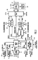
- a source 10 of interlaced video signal "I” and a source 12 of progressive video signal "P" in a broadcast television encoder/transmitter provide output video signals to respective inputs of an automatic scan format converter 14 which operates in accordance with the principles of the present invention.
- Scan converter 14 will be shown and described in greater detail with regard to Figure 2.
- the television system is an HDTV system of the type proposed by the Grand Alliance in the United States as noted above.
- Video sources 10 and 12 are mutually synchronized ("genlocked"). In this example only one of these sources is active at a time, although in some systems both may be active. In the case where only one of the signal sources is active at a time, converter automatically selects the input port with the active video signal. If the scanning format of the active video signal is the same as the format desired for a transmitted video signal, the scanning format of the input video signal is not altered by converter 14. If the input format is different, converter 14 automatically converts the format of the input video signal so as to be compatible with the desired output signal format.
- the output signal from scan converter 14 is data compressed by an MPEG encoder 16, as known, before being applied to a transport processor 18.
- Processor 18 formats compressed data from encoder 16 into data packets, prefaces the data packets with header information which identifies the contents of the respective packets, and adds synchronizing and other information, for example.
- Data packets from transport processor 18 are processed for transmission via a transmission channel 25 by a transmission processor 20.
- Processor 20 includes data formatting, error coding, buffering, digital to analog converter and RF (radio frequency) modulating networks for conditioning the video signal for transmission via channel 25.
- the signal from channel 25 is first processed by a unit 30 including RF tuning and filtering networks, IF (intermediate frequency) networks, demodulation and error processing networks, and an analog to digital converter, for example.
- An output signal from unit 30 is processed by a unit 32 which performs the inverse of the operation of unit 18 at the transmitter. Specifically, unit 32 evaluates header information for identifying the constituent data packet components and separates these components (e.g., video, audio and synchronization information) for processing by respective circuits.
- the data components from decoder 32 are decompressed by an MPEG decoder 34 as known.
- MPEG decoder 34 includes an interlaced video signal output port at which a transmitted 1080 line interlaced video signal would appear, and a progressive video signal output port at which a transmitted 720 line progressive video signal would appear. MPEG decoder 34 also includes provision for deriving coded information from the received data stream indicating whether a received video signal exhibits interlaced or progressive form.
- a television receiver includes an associated display device which may be an interlaced scan type or a progressive scan type. These possibilities are illustrated by means of an interlaced display device 38 and a progressive display device 39. A practical receiver will have one but not both of such display devices.
- the receiver display device receives a signal to be displayed from a format converter 36 (after processing by appropriate signal conditioning and display driver circuits not shown to simplify the drawing).
- Format converter 36 is programmed with information (e.g., by the receiver manufacturer or via a locally generated control signal) to indicate the type of the associated display, i.e., interlaced or progressive, since in this example it is assumed that an associated display device is able to display video information in only one scanning format. Accordingly, format converter 36 is arranged to automatically provide an output signal in a format compatible with the display device, regardless of which of the two video signal formats is received and decoded.
- converter 36 will bypass a received interlaced video signal from unit 34 to the output of converter 36 without modifying its scan format. If a received video signal is progressive, converter 36 will automatically sense this by sensing that the progressive outport of MPEG decoder 34 is active, convert such signal to interlaced form, and provide such signal at its interlaced signal output. Thus an interlaced video signal will always be provided to an interlaced display regardless of the scanning format of a transmitted video signal. Analogous observations pertain to a receiver with an associated progressive display such as device 39.
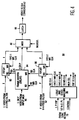
- Figure 2 shows additional details of a scan format converter such as units 14 and 36 in Figure 1.
- An input network 42 and an input network 44 respectively receive digital interlaced (I) and digital progressive (P) output signals from MPEG decoder 34.
- the input networks each include circuits for separating the video component and synchronizing components.
- the sync components include a horizontal sync component (H), a vertical sync component (V), a frame reference pulse (FRP) and a pixel clock CLK.
- the frequency of the pixel clock is derived from the product of the total number of pixels, the total number of lines, and the number of fields/second.
- Frame reference pulse FRP is a reference signal developed by MPEG decoder 34. It appears in a prescribed portion of the vertical blanking interval, and provides a reference point from which subsequent circuits count clocks to the first pixel of an interlaced field or a progressive frame.
- Converter 36 also includes an analog input for receiving analog R, G, B (or Y, U, V) color video components and associated horizontal and vertical synchronizing components H, V. These components may be generated by a video cassette recorder (VCR) or a video camera for example, and are converted to digital form by an analog to digital converter 48. Video outputs from units 42, 44 and 48 are applied to respective signal inputs of an input multiplexer (MUX) 46.
- VCR video cassette recorder
- MUX input multiplexer
- a synchronization and mode control unit 70 responds to digital sync components H and V, frame reference pulses FRP, and clocks CLK for both interlaced and progressive source signals, as well as to H and V sync components (H, V RGB) for the analog signal source after conversion to digital form by converter 48.
- a control input of network 70 receives an Output Format Control signal for determining the operating characteristics of the format converter as a function of whether an interlaced or progressive format is desired for an output video signal. This signal may be produced by a local switch setting, and determines whether the output video signal will be interlaced or progressive. This determination may be made by a broadcast operator at a transmitter, or by a receiver manufacturer.
- Output signals produced by network 70 include a frame reference pulse FRP(I) for interlaced signals, a frame reference pulse FRP(P) for progressive signals, a picture element (pixel) clock fs, a half-rate pixel clock 1/2 fs, and a Control signal.
- the Control signal is applied to an output multiplexer 60 for conveying either interlaced or a progressive video signal to an output, as will be discussed.
- Network 70 may include a phase locked loop (PLL) network frame and field locked by means of the FRP signals.
- PLL phase locked loop
- the pixel clock fs for an interlaced video signal is a 74.25 MHz signal (2200 pixels x 1125 lines total x 30 Hz field rate).
- Video information is transferred to the converter system via A/D unit 48 and input MUX 46, and from the converter system via D/A unit 62, at full pixel rate fs.
- the subsystems within the format converter operate in response to the 1/2 fs clock.
- Progressive to interlaced format conversion (720 lines to 540 lines) is accomplished by means of a P-I Conversion Path including input MUX 46, a horizontal and vertical pre-filter 54 which performs 4:3 decimation, an output MUX 60 and a digital to analog converter 62.
- Interlaced to progressive format conversion is accomplished by means of an I-P Conversion Path including MUX 46, a line doubling de-interlacer 50, a horizontal and vertical post-filter network 52 which performs 3:2 decimation, output MUX 60 and converter 62.
- Techniques for performing interpolation and decimation are well known.
- the video signal is conveyed via a Bypass Path including input MUX 46, output MUX 60 and digital to analog converter 62.
- frame Reference Pulses FRP and video information are respectively converted to analog sync components H, V and analog color video components R, G and B by means of converter 62. These components are then conveyed to synchronization and video signal processing and display driver circuits as known.
- Output port 64 is used only at a transmitter/encoder format encoder, e.g., unit 14 in Figure 1, to convey digital information to MPEG coder 16.
- D/A converter 62 includes a Programmable Logic Network (as known) with a counter for generating the output H and V sync components.
- the FRP is applied to a reset input of the counter, and the Programmable Logic Network operates in response to clock fs and an output format select signal (derived from the Control signal) for producing the H and V output sync components after conversion to analog form.
- input MUX 46 receives a digital video signal, e.g., from units 42 or 48, at the pixel clock rate. MUX 46 then generates an output signal at one-half the input data rate. Specifically, pixel data arriving in a time sequence A, B, C, D,.... are converted to a datastream of two pixels in parallel, e.g., A, B then C, D and so forth. This datastream is provided to an input of deinterlacing unit 50, which also receives a FRP sync component from unit 46. De-interlacing unit 50 operates as known by storing odd field lines 1, 3, 5,... and even field lines 2, 4, 6,...
- a video frame is generated by creating additional lines in every field so that an output signal from unit 50 represents a progressive video frame constituted by lines 1, 2, 3, 4, 5, 6, ... and so forth.
- This deinterlacing operation could be as simple as repeating lines, or as elaborate as estimating motion in each field for each of the R, G, B color signal components and using the derived motion vectors to adjust coefficients in various directions to produce additional pixels, as known.
- unit 50 finds the greatest motion vector from among the three RGB color components. This vector is used by interpolation networks to generate new pixel values for the derived line.
- unit 50 generates an output signal with twice as many lines as the input signal, i.e., 1080 lines derived from the 540 lines in each field.
- Horizontal and vertical postfilter 52 subjects the output video signal from unit 50 to 3:2 decimation in the horizontal direction to generate 1280 output pixels from 1920 input pixels. In the vertical direction, filter 52 decimates the output signal from unit 50 by 3:2 to generate 720 output lines from 1080 input lines. This progressive signal is routed via MUX 60 and DAC 62 to subsequent signal processing and display circuits.
- an output signal from MUX 46 and the FRP component are applied to a horizontal and vertical pre-filter 54.
- Filter 54 subjects the video signal to 2:3 interpolation in the horizontal direction to generate 1920 output pixels from 1280 input pixels.
- filter 54 subjects the video signal to 2:3 decimation to generate 1080 output lines from 720 input lines.
- the interlaced output signal from unit 54 is routed via MUX 60 and DAC 62 to subsequent signal processing and display circuits.
- the FRP timing at the outputs of units 52 and 54 remains fixed.
- Output MUX 60 includes a frame memory (delay) network in the Bypass Path to compensate for signal processing delays associated with the P-I conversion path and the I-P conversion path. This frame delay also facilitates the seamless switching between video signals of different format. Switching occurs at frame boundaries. The frame delay allows the input video to switch randomly between the two formats and still provide an output signal in the desired format in a continuous stream without dropping any frames. If the format converter is arranged to provide a progressive scan output, the input signal format can change between progressive and interlaced format without disrupting the signal data flow or losing video information in the output signal of the format converter.
- This feature allows, for example, a television commercial to be in progressive scan format while television main program material is in interlace scan format.
- Both types of video information when merged into a similar scan format using the seamless switching feature of the format converter, can be transmitted and received in real-time as one continuous stream of video information. This feature will be shown and discussed in connection with Figures 3 and 4.
- the format converter operates to convert the incoming progressive format to the desired output interlaced format.
- Pre-filter 54 in Figure 2 exhibits a processing delay of slightly more than one frame duration for converting from progressive to interlaced format. The magnitude of this delay is not critical, but should be a known, fixed delay.
- mode control network 70 Assume that while the converted interlaced signal is being transferred to output MUX 60, the format of the input signal changed from progressive to interlaced (which is the desired output format). This change is detected by mode control network 70.
- the Control signal provided by network 70 to output MUX 60 indicates that this format change has occurred, causing output MUX 60 to begin storing the new interlaced input video signal that is conveyed directly from the output of input MUX 46 to output MUX 60 via the Bypass Path.
- MUX 60 stores this interlaced signal in a frame buffer memory.
- the frame buffer delay allows output MUX 60 to route the processed progressive video signal from filter 54 in its entirety to output DAC unit 62 for display, followed by the bypassed interlaced video from the frame buffer.
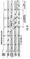
- Waveform A illustrates the position of Frame Reference Pulse FRP during the vertical blanking interval prior to the active video line scanning interval. The interval between each FRP is one image frame in this example.
- pin-0 and pin-1 represent input progressive video frames. These frames appear delayed at the output of pre-filter 54 ( Figure 2) as waveform (C) data hvpre-0 and hvpre-1. After conversion to interlaced format, these frames respectively appear as output interlaced video iout-0 and iout- 1 shown in waveform (E).
- output video information iout-0 corresponds to input frame pin-0.
- Output video information iout-1 corresponds to input progressive video pin-1, and is the last progressive-to-interlace converted frame to appear before the input signal changes to interlaced format.
- output MUX 60 delays HVPRE filtered data by a few lines as will be explained in connection with Figure 4.
- the output MUX delays the video information in the Bypass path by 2 frames, as will also be discussed in connection with Figure 4.
- the input video signal changes to interlaced format at a time T0.
- These new interlaced frames are labeled iin-0 and iin-1 in waveform D.
- the interlaced video is subjected to a two frame delay associated with output MUX 60 as noted above, respectively resulting in iout-2 as shown in waveform E.
- the bypassed interlaced video appears at the output at time T1 and onward.
- interlaced data iout-2 which appears just after a time T1 at a frame boundary, is the first output data from the new interlaced input video signal. From time T1 onward, i.e., from the first line of the next image frame, the video lines continue seamlessly without interruption.
- an interlaced format is produced seamlessly from data iout-0 to data iout-2 etc. as the video input changes from progressive to interlaced format.
- the switch from a progressive format (waveform B) to interlaced format (waveform D) produces no visible artifacts and is unnoticed by a viewer.
- the format transition occurs a predetermined fixed amount of time (delay) after the appearance of the FRP to facilitate the seamless transition and avoid a discontinuity in a displayed image.
- Figure 3B illustrates the seamless switching process in the case of providing a progressive video output signal format. This is accomplished in a manner analogous to that discussed with respect to Figure 3A for an interlaced output signal format.
- a waveform C associated with the output of de-interlacer 50 in Figure 2
- a waveform D associated with the output of HV Post filter 52 in the I-P path in the Figure 2 system.
- Waveform D in Figure 3B is analogous to waveform C in Figure 3A.
- Figure 4 shows details of output MUX 60.
- a multiplexer 80 receives an interlaced video input signal from a first FIFO buffer 82, a progressive video input signal from a second FIFO buffer 86, and either an interlaced or a progressive video signal from a frame buffer 84. Interlaced video signals are provided to buffer 82 from prefilter 54 ( Figure 2) in the P-I conversion path, input video signals are directly provided to frame buffer 84 from input MUX 46 ( Figure 2), and progressive video input signals are provided to buffer 86 from post filter 52 ( Figure 2) in the I-P conversion path.
- the size of buffers 82 and 86 is not critical, e.g., several video lines. Buffers 82 and 86 are used to compensate for the different signal delays associated with the three different input sources.
- Frame buffer 84 receives data directly from input MUX 60 in Figure 2.
- Buffer 84 exhibits a two frame delay in this example. However, a one frame delay may be used in accordance with the requirements of other systems.
- Output signals from MUX 80 are conveyed to D/A converter 62 ( Figure 2) via latch 90.
- output MUX 60 in Figure 2 receives three Frame Reference Pulses (FRP), one from each of filters 52 and 54 and another from input MUX 46. These pulses may be misaligned among each other by a few image lines. The clock-to-data timing may also be misaligned among the three sources. Therefore FIFO buffers are used to "clean up" any delay and timing misalignment before the seamless switching operation associated with MUX 80 in Figure 4. For this purpose buffers 82 and 84 exhibit a small delay of a few image lines to place processed data near a frame boundary to facilitate seamless switching.
- FRP Frame Reference Pulses
- Seamless format switching by MUX 80 is facilitated by the read/write clocking of buffers 82, 84 and 86, and by the referencing of the FRP pulses.
- the data write clock for preceding buffer 82 (FIFO 1 WR CLK) is aligned with the 1/2 fs clock for filter 54.
- the write clock for frame buffer 84 (FB WR CLK) is aligned with the 1/2 fs clock for input MUX 46.
- the data read clocks for buffers 82 and 84 are the same (RD CLK).
- the FRP pulse from the output MUX is referenced from the FRP pulse from the input MUX.
- Output data from buffer 82 and from frame buffer 84 are referenced to the same clock edge. Analogous observations apply to buffers 84 and 86 when the converter is in the interlaced-to-progressive conversion mode.
- Unit 95 also outputs a MUXSEL signal which is applied to a control input of MUX 80.
- MUX 80 selects as its input either (a) the output from buffer 82 or the output of frame buffer 84, or (b) the output of buffer 86 or the output of frame buffer 84.
- MUX 80 selects between the two choices in (a) and the two choices in (b) in response to the MUXSEL control signal from state machine 95, which signal is in turn developed in response to the Control signal from network 70 in Figure 2.
- These control signals indicate which of conversions P-I or I-P are present, or bypass conditions I-I or P-P where no conversion is to be made.
- An output FRP from unit 95 is applied to D/A converter 62 in Figure 2.
- the interlaced and progressive frame reference pulses FRP(I) and FRP(P) are provided from preceding circuits, e.g., decoder 34 of Figure 1 in the case of a receiver, for example.
- network 70 of Figure 1 may for example include a phase locked loop (PLL) responsive to the input analog H sync component for producing related input and output clocks.
- the output clock may be applied to a counter, a reset input of which receives the V sync component.
- the counter outputs H and V sync signals as well as FRP(I) and FRP(P) signals at predetermined times suitable for use by the elements of the system of Figure 2.
Applications Claiming Priority (2)
| Application Number | Priority Date | Filing Date | Title |
|---|---|---|---|
| US446092 | 1995-05-19 | ||
| US08/446,092 US5610661A (en) | 1995-05-19 | 1995-05-19 | Automatic image scanning format converter with seamless switching |
Publications (2)
| Publication Number | Publication Date |
|---|---|
| EP0743788A1 true EP0743788A1 (fr) | 1996-11-20 |
| EP0743788B1 EP0743788B1 (fr) | 2001-01-31 |
Family
ID=23771291
Family Applications (1)
| Application Number | Title | Priority Date | Filing Date |
|---|---|---|---|
| EP96107507A Expired - Lifetime EP0743788B1 (fr) | 1995-05-19 | 1996-05-10 | Convertisseur automatique de format de balayage d'image avec commutation sans joint |
Country Status (9)
| Country | Link |
|---|---|
| US (1) | US5610661A (fr) |
| EP (1) | EP0743788B1 (fr) |
| JP (2) | JP4350807B2 (fr) |
| KR (1) | KR100426889B1 (fr) |
| CN (1) | CN1083661C (fr) |
| DE (1) | DE69611702T2 (fr) |
| MY (1) | MY112052A (fr) |
| SG (1) | SG63645A1 (fr) |
| TW (1) | TW453115B (fr) |
Cited By (4)
| Publication number | Priority date | Publication date | Assignee | Title |
|---|---|---|---|---|
| EP0860992A2 (fr) * | 1997-02-20 | 1998-08-26 | Matsushita Electric Industrial Co., Ltd. | Récepteur de télévision avec un convertisseur de balayage |
| EP0918436A2 (fr) * | 1997-11-21 | 1999-05-26 | Nec Corporation | Conversion du système de balayage en un système de balayage progressif indépendamment du système de balayage avant codage |
| EP0935385A2 (fr) * | 1998-02-04 | 1999-08-11 | Hitachi, Ltd. | Dispositif de décodage et récepteur l'utilisant |
| GB2411305A (en) * | 2004-02-19 | 2005-08-24 | Tandberg Television Ltd | Selecting between a de-interlaced signal and a delayed progressive signal dependent on the type of input signal detected |
Families Citing this family (69)
| Publication number | Priority date | Publication date | Assignee | Title |
|---|---|---|---|---|
| US20010013123A1 (en) * | 1991-11-25 | 2001-08-09 | Freeman Michael J. | Customized program creation by splicing server based video, audio, or graphical segments |
| US20020129374A1 (en) * | 1991-11-25 | 2002-09-12 | Michael J. Freeman | Compressed digital-data seamless video switching system |
| JPH09507349A (ja) * | 1993-12-29 | 1997-07-22 | ライカ アクチエンゲゼルシャフト | 表示装置上に立体ビデオ映像を表示するための方法及び装置 |
| KR100234583B1 (ko) * | 1994-06-14 | 2000-01-15 | 모리시타 요이찌 | 비디오 신호 기록 장치, 비디오 신호 기록 및 재생 장치, 비디오 신호 코딩 장치, 및 비디오 신호 전송 장치 |
| EP0860080B1 (fr) * | 1995-11-08 | 1999-06-09 | Genesis Microchip Inc. | Procede et appareil permettant de des-entrelacer des champs video pour creer des trames video de balayage progressif |
| US5963261A (en) * | 1996-04-29 | 1999-10-05 | Philips Electronics North America Corporation | Low cost scan converter for television receiver |
| JP3164292B2 (ja) * | 1996-10-11 | 2001-05-08 | 日本ビクター株式会社 | 動画像符号化装置、動画像復号化装置および動画像符号記録方法 |
| JPH10191191A (ja) * | 1996-12-26 | 1998-07-21 | Hitachi Ltd | 映像表示装置 |
| US5905873A (en) * | 1997-01-16 | 1999-05-18 | Advanced Micro Devices, Inc. | System and method of routing communications data with multiple protocols using crossbar switches |
| JPH10290440A (ja) * | 1997-04-14 | 1998-10-27 | Matsushita Electric Ind Co Ltd | ディジタル放送送信方法、ディジタル放送送信装置、及びディジタル放送再生装置 |
| US6069664A (en) * | 1997-06-04 | 2000-05-30 | Matsushita Electric Industrial Co., Ltd. | Method and apparatus for converting a digital interlaced video signal from a film scanner to a digital progressive video signal |
| JP3564961B2 (ja) * | 1997-08-21 | 2004-09-15 | 株式会社日立製作所 | ディジタル放送受信装置 |
| US6437828B1 (en) * | 1997-09-30 | 2002-08-20 | Koninklijke Philips Electronics N.V. | Line-quadrupler in home theater uses line-doubler of AV-part and scaler in graphics controller of PC-part |
| US6055018A (en) * | 1997-11-04 | 2000-04-25 | Ati Technologies, Inc. | System and method for reconstructing noninterlaced captured content for display on a progressive screen |
| KR100235988B1 (ko) * | 1997-11-12 | 1999-12-15 | 구자홍 | 디티브이 영상 포맷 변환장치 및 그 방법 |
| US6084568A (en) * | 1997-11-13 | 2000-07-04 | S3 Incorporated | System and methods for both 2-tap and 3-tap flicker filtering of non-interlaced computer graphics to interlaced lines for television display |
| US6873368B1 (en) * | 1997-12-23 | 2005-03-29 | Thomson Licensing Sa. | Low noise encoding and decoding method |
| KR100455055B1 (ko) * | 1997-12-24 | 2005-01-05 | 주식회사 대우일렉트로닉스 | 멀티입력hd모니터의데이터저장방법 |
| DE19808005A1 (de) * | 1998-02-26 | 1999-09-02 | Philips Patentverwaltung | Anordnung zum Bearbeiten von Videosignalen |
| US6108046A (en) * | 1998-06-01 | 2000-08-22 | General Instrument Corporation | Automatic detection of HDTV video format |
| KR20000001754A (ko) * | 1998-06-13 | 2000-01-15 | 윤종용 | 순차주사방식의 투사형 영상 디스플레이장치 |
| JP2002520956A (ja) * | 1998-07-08 | 2002-07-09 | コーニンクレッカ フィリップス エレクトロニクス エヌ ヴィ | インタレース画像用チャネルによる順次走査画像の伝送 |
| US6297847B1 (en) * | 1998-08-03 | 2001-10-02 | S3 Graphics Co., Ltd. | Removal of interpolation artifacts in a non-interlaced video stream |
| KR20040010726A (ko) * | 1998-09-16 | 2004-01-31 | 에이씨티브이, 인크. | 제1 및 제2 비디오 신호들을 동시에 디스플레이하는 수신기 |
| JP3821415B2 (ja) * | 1998-09-30 | 2006-09-13 | 日本ビクター株式会社 | 動画像フォーマット変換装置及びその方法 |
| US6122015A (en) * | 1998-12-07 | 2000-09-19 | General Electric Company | Method and apparatus for filtering digital television signals |
| JP2002534916A (ja) * | 1999-01-05 | 2002-10-15 | インフィネオン テヒノロギーズ アーゲー | デジタルtvシステムのための信号処理装置 |
| JP3721867B2 (ja) * | 1999-07-07 | 2005-11-30 | 日本電気株式会社 | 映像表示装置及び表示方法 |
| US6633344B1 (en) | 1999-07-15 | 2003-10-14 | Thomson Licensing S.A. | Processing of progressive video signals in digital TV receivers |
| JP3837690B2 (ja) * | 1999-12-03 | 2006-10-25 | パイオニア株式会社 | 映像信号処理装置 |
| US6704493B1 (en) * | 2000-03-06 | 2004-03-09 | Sony Corporation | Multiple source recording |
| US6940911B2 (en) * | 2000-03-14 | 2005-09-06 | Victor Company Of Japan, Ltd. | Variable picture rate coding/decoding method and apparatus |
| KR100385975B1 (ko) * | 2000-08-23 | 2003-06-02 | 삼성전자주식회사 | 비디오 포맷 변환장치 및 방법 |
| US6316974B1 (en) | 2000-08-26 | 2001-11-13 | Rgb Systems, Inc. | Method and apparatus for vertically locking input and output signals |
| KR100472436B1 (ko) | 2000-08-29 | 2005-03-07 | 삼성전자주식회사 | 디지털 텔레비전에서의 적응적 외부 입력 비디오 신호의처리장치 |
| US7006147B2 (en) * | 2000-12-22 | 2006-02-28 | Thomson Lincensing | Method and system for MPEG chroma de-interlacing |
| US7236204B2 (en) * | 2001-02-20 | 2007-06-26 | Digeo, Inc. | System and method for rendering graphics and video on a display |
| US20020194589A1 (en) * | 2001-05-08 | 2002-12-19 | Cristofalo Michael | Technique for optimizing the delivery of advertisements and other programming segments by making bandwidth tradeoffs |
| KR100385993B1 (ko) * | 2001-06-13 | 2003-06-02 | 삼성전자주식회사 | 디브이디, 디티브이 입력신호 판별 장치 |
| KR100429204B1 (ko) * | 2001-07-12 | 2004-04-28 | 엘지전자 주식회사 | 디브이디의 색차 신호 자동인식장치 |
| US20030058707A1 (en) * | 2001-09-12 | 2003-03-27 | Dilger Bruce C. | System and process for implementing commercial breaks in programming |
| US8582031B2 (en) * | 2002-01-22 | 2013-11-12 | Broadcom Corporation | System and method of transmission and display of progressive video with hints for interlaced display |
| US7075899B2 (en) * | 2002-05-21 | 2006-07-11 | Actv, Inc. | System and method for providing private in-band data to digital set-top boxes in a broadcast environment |
| US6894726B2 (en) * | 2002-07-05 | 2005-05-17 | Thomson Licensing S.A. | High-definition de-interlacing and frame doubling circuit and method |
| JP2004173182A (ja) * | 2002-11-22 | 2004-06-17 | Toshiba Corp | 画像表示装置及び走査線変換表示方法 |
| JP2005026885A (ja) * | 2003-06-30 | 2005-01-27 | Toshiba Corp | テレビジョン受信装置及びその制御方法 |
| TWI232681B (en) * | 2003-08-27 | 2005-05-11 | Mediatek Inc | Method of transforming one video output format into another video output format without degrading display quality |
| TWI282546B (en) * | 2004-04-02 | 2007-06-11 | Mstar Semiconductor Inc | Display controlling device capable of displaying multiple windows and related method |
| US7375768B2 (en) * | 2004-08-24 | 2008-05-20 | Magix Ag | System and method for automatic creation of device specific high definition material |
| JP2006129069A (ja) * | 2004-10-28 | 2006-05-18 | Canon Inc | 撮像装置及び撮像方法 |
| TWI249359B (en) * | 2004-12-22 | 2006-02-11 | Realtek Semiconductor Corp | Method and apparatus for simultaneous progressive and interlaced display |
| US7729239B1 (en) * | 2004-12-27 | 2010-06-01 | Emc Corporation | Packet switching network end point controller |
| CN101283598B (zh) * | 2005-07-28 | 2011-01-26 | 汤姆森许可贸易公司 | 用于产生内插帧的设备 |
| KR100846450B1 (ko) * | 2006-08-31 | 2008-07-16 | 삼성전자주식회사 | 해상도 자동 선택방법 및 이를 적용한 영상수신장치 |
| TWI342163B (en) * | 2006-10-11 | 2011-05-11 | Princeton Technology Corp | Av player chip, av system, and related method capable of sharing digital-to-analog converter |
| US20080117329A1 (en) * | 2006-11-22 | 2008-05-22 | Richard Hayden Wyman | Multi-mode video deinterlacer comprising a low delay mode |
| US8054382B2 (en) * | 2007-05-21 | 2011-11-08 | International Business Machines Corporation | Apparatus, method and system for synchronizing a common broadcast signal among multiple television units |
| KR20110073469A (ko) * | 2008-09-01 | 2011-06-29 | 미쓰비시 디지털 전자 아메리카, 인크. | 영상 개선 시스템 |
| JP2010124193A (ja) * | 2008-11-19 | 2010-06-03 | Nec Electronics Corp | 映像信号処理装置及び映像信号処理方法 |
| TWI402798B (zh) * | 2009-04-29 | 2013-07-21 | Chunghwa Picture Tubes Ltd | 具省電功能之時序控制器 |
| JP4724240B2 (ja) * | 2009-07-02 | 2011-07-13 | トムソン ライセンシング | ビデオ信号を処理する方法 |
| US8553072B2 (en) | 2010-11-23 | 2013-10-08 | Circa3D, Llc | Blanking inter-frame transitions of a 3D signal |
| US9524008B1 (en) * | 2012-09-11 | 2016-12-20 | Pixelworks, Inc. | Variable frame rate timing controller for display devices |
| TWI492212B (zh) * | 2013-05-07 | 2015-07-11 | Au Optronics Corp | 驅動裝置及驅動方法 |
| US9135672B2 (en) | 2013-05-08 | 2015-09-15 | Himax Technologies Limited | Display system and data transmission method thereof |
| US8928808B2 (en) * | 2013-05-24 | 2015-01-06 | Broadcom Corporation | Seamless transition between interlaced and progressive video profiles in an ABR system |
| TWI493537B (zh) * | 2013-06-05 | 2015-07-21 | Himax Tech Ltd | 顯示系統及其資料傳遞方法 |
| KR101601968B1 (ko) * | 2014-07-10 | 2016-03-09 | (주)글로벌엔지니어링 | 오일미스트 처리장치 |
| US10687011B2 (en) * | 2016-03-28 | 2020-06-16 | Techpoint, Inc. | Method and apparatus for improving transmission of transport video signal |
Citations (4)
| Publication number | Priority date | Publication date | Assignee | Title |
|---|---|---|---|---|
| US5132793A (en) * | 1989-03-10 | 1992-07-21 | Hitachi, Ltd. | Television receiver compatible with both standard system television signal and high definition television signal |
| US5327240A (en) * | 1991-12-24 | 1994-07-05 | Texas Instruments Incorporated | Methods, systems and apparatus for providing improved definition video |
| EP0639029A2 (fr) * | 1993-08-07 | 1995-02-15 | Goldstar Co. Ltd. | Dispositif pour convertir le format d'image d'un signal de télévision |
| EP0639923A2 (fr) * | 1993-08-18 | 1995-02-22 | Goldstar Co. Ltd. | Appareil de conversion de format vidéo pour télévision à haute définition |
Family Cites Families (14)
| Publication number | Priority date | Publication date | Assignee | Title |
|---|---|---|---|---|
| US4677482A (en) * | 1985-12-31 | 1987-06-30 | Rca Corporation | Dual mode progressive scan system with automatic mode switching by image analysis |
| GB8628813D0 (en) * | 1986-12-02 | 1987-01-07 | British Broadcasting Corp | Video display system |
| JPH03258169A (ja) * | 1990-03-08 | 1991-11-18 | Mitsubishi Electric Corp | ディジタル映像信号処理装置 |
| JP2642524B2 (ja) * | 1991-04-04 | 1997-08-20 | 沖電気工業株式会社 | 画像のフレーム内符号化器及び復号化器 |
| JPH0541878A (ja) * | 1991-08-05 | 1993-02-19 | Mitsubishi Electric Corp | テレビジヨン方式変換器 |
| JP3190711B2 (ja) * | 1991-10-31 | 2001-07-23 | 株式会社日立国際電気 | 映像走査周波数変換装置の制御方法 |
| JPH05316471A (ja) * | 1992-04-17 | 1993-11-26 | Sony Corp | 静止画表示装置 |
| US5347318A (en) * | 1992-06-16 | 1994-09-13 | Canon Kabushiki Kaisha | Apparatus for processing video signals having different aspect ratios |
| DE69332302T2 (de) * | 1992-11-23 | 2003-01-30 | Thomson Multimedia Sa | Verfahren und Vorrichtung zur adaptiver Umsetzung in ein Zeilenfolgesignal |
| US5444491A (en) * | 1993-02-26 | 1995-08-22 | Massachusetts Institute Of Technology | Television system with multiple transmission formats |
| JPH06292153A (ja) * | 1993-04-07 | 1994-10-18 | Fujitsu General Ltd | 映像信号変換方法 |
| US5410357A (en) * | 1993-04-12 | 1995-04-25 | The United States Of America As Represented By The Secretary Of The Navy | Scan converter and method |
| JPH0759056A (ja) * | 1993-08-10 | 1995-03-03 | Sony Corp | テレビジョン受像機 |
| JP3318633B2 (ja) * | 1993-09-24 | 2002-08-26 | ソニー株式会社 | 映像信号変換装置 |
-
1995
- 1995-05-19 US US08/446,092 patent/US5610661A/en not_active Expired - Lifetime
-
1996
- 1996-05-10 DE DE69611702T patent/DE69611702T2/de not_active Expired - Lifetime
- 1996-05-10 EP EP96107507A patent/EP0743788B1/fr not_active Expired - Lifetime
- 1996-05-14 MY MYPI96001807A patent/MY112052A/en unknown
- 1996-05-15 SG SG1996009801A patent/SG63645A1/en unknown
- 1996-05-16 TW TW085105808A patent/TW453115B/zh not_active IP Right Cessation
- 1996-05-17 KR KR1019960016552A patent/KR100426889B1/ko not_active IP Right Cessation
- 1996-05-18 CN CN96106331A patent/CN1083661C/zh not_active Expired - Lifetime
- 1996-05-20 JP JP12504896A patent/JP4350807B2/ja not_active Expired - Lifetime
-
2008
- 2008-07-02 JP JP2008173855A patent/JP4724734B2/ja not_active Expired - Lifetime
Patent Citations (4)
| Publication number | Priority date | Publication date | Assignee | Title |
|---|---|---|---|---|
| US5132793A (en) * | 1989-03-10 | 1992-07-21 | Hitachi, Ltd. | Television receiver compatible with both standard system television signal and high definition television signal |
| US5327240A (en) * | 1991-12-24 | 1994-07-05 | Texas Instruments Incorporated | Methods, systems and apparatus for providing improved definition video |
| EP0639029A2 (fr) * | 1993-08-07 | 1995-02-15 | Goldstar Co. Ltd. | Dispositif pour convertir le format d'image d'un signal de télévision |
| EP0639923A2 (fr) * | 1993-08-18 | 1995-02-22 | Goldstar Co. Ltd. | Appareil de conversion de format vidéo pour télévision à haute définition |
Cited By (14)
| Publication number | Priority date | Publication date | Assignee | Title |
|---|---|---|---|---|
| EP0860992A3 (fr) * | 1997-02-20 | 1999-04-21 | Matsushita Electric Industrial Co., Ltd. | Récepteur de télévision avec un convertisseur de balayage |
| EP0860992A2 (fr) * | 1997-02-20 | 1998-08-26 | Matsushita Electric Industrial Co., Ltd. | Récepteur de télévision avec un convertisseur de balayage |
| EP0918436A3 (fr) * | 1997-11-21 | 2000-04-12 | Nec Corporation | Conversion du système de balayage en un système de balayage progressif indépendamment du système de balayage avant codage |
| EP0918436A2 (fr) * | 1997-11-21 | 1999-05-26 | Nec Corporation | Conversion du système de balayage en un système de balayage progressif indépendamment du système de balayage avant codage |
| US6452638B1 (en) | 1998-02-04 | 2002-09-17 | Hitachi, Ltd. | Decoder device and receiver using the same |
| EP0935385A3 (fr) * | 1998-02-04 | 2002-06-19 | Hitachi, Ltd. | Dispositif de décodage et récepteur l'utilisant |
| EP0935385A2 (fr) * | 1998-02-04 | 1999-08-11 | Hitachi, Ltd. | Dispositif de décodage et récepteur l'utilisant |
| US6710817B2 (en) | 1998-02-04 | 2004-03-23 | Hitachi, Ltd. | Decoder device and receiver using the same |
| US7375761B2 (en) | 1998-02-04 | 2008-05-20 | Hitachi, Ltd. | Receiver having motion picture data decoder |
| US7643089B2 (en) | 1998-02-04 | 2010-01-05 | Hitachi, Ltd. | Decoder device and receiver using the same |
| GB2411305A (en) * | 2004-02-19 | 2005-08-24 | Tandberg Television Ltd | Selecting between a de-interlaced signal and a delayed progressive signal dependent on the type of input signal detected |
| EP1566963A2 (fr) * | 2004-02-19 | 2005-08-24 | Tandberg Television ASA | Détection et sélection de signaux à balayage progessif ou de signaux entrelacés |
| EP1566963A3 (fr) * | 2004-02-19 | 2007-06-13 | Tandberg Television ASA | Détection et sélection de signaux à balayage progessif ou de signaux entrelacés |
| US7417688B2 (en) | 2004-02-19 | 2008-08-26 | Tandberg Television Asa | Detecting and selecting between progressive scanned and interlaced signals |
Also Published As
| Publication number | Publication date |
|---|---|
| CN1143298A (zh) | 1997-02-19 |
| JPH08322023A (ja) | 1996-12-03 |
| JP4350807B2 (ja) | 2009-10-21 |
| MY112052A (en) | 2001-03-31 |
| KR960043872A (ko) | 1996-12-23 |
| DE69611702T2 (de) | 2001-05-23 |
| JP2008236812A (ja) | 2008-10-02 |
| DE69611702D1 (de) | 2001-03-08 |
| KR100426889B1 (ko) | 2004-08-25 |
| JP4724734B2 (ja) | 2011-07-13 |
| SG63645A1 (en) | 1999-03-30 |
| CN1083661C (zh) | 2002-04-24 |
| US5610661A (en) | 1997-03-11 |
| TW453115B (en) | 2001-09-01 |
| EP0743788B1 (fr) | 2001-01-31 |
Similar Documents
| Publication | Publication Date | Title |
|---|---|---|
| EP0743788B1 (fr) | Convertisseur automatique de format de balayage d'image avec commutation sans joint | |
| EP0743791B1 (fr) | Convertisseur du format de balayage d'image approprié à un système de télévision à haute résolution | |
| EP1011267B1 (fr) | Récepteur pour l'affichage simultané de signaux ayant des formats d'affichage différents et/ou ayant des fréquences de trame différentes et procédé d'affichage associé | |
| US4881125A (en) | Progressive scan display of video derived from film | |
| US5132793A (en) | Television receiver compatible with both standard system television signal and high definition television signal | |
| US5144427A (en) | Television receiver decoder apparatus for bandwidth-compressed high definition television signal | |
| EP0860992B1 (fr) | Récepteur de télévision avec un convertisseur de balayage et procédé correspondant | |
| US6900845B1 (en) | Memory architecture for a multiple format video signal processor | |
| US6836294B2 (en) | Method of decreasing delay through frame based format converters | |
| WO1988000783A1 (fr) | Ameliorations apportees a des signaux de television | |
| KR100311009B1 (ko) | 공통 포맷을 이용하는 영상 포맷 변환 장치와 그 방법 | |
| US5495293A (en) | Frame synchronizer and a signal switching apparatus | |
| JP3325445B2 (ja) | 映像信号処理装置 | |
| MXPA96001881A (en) | Automatic converter of image examination format with switching without cost | |
| MXPA96001882A (en) | Image exploring format converter suitable for a high definic television system | |
| KR0159531B1 (ko) | 뮤즈/엔티에스시 텔레비젼 신호 변환장치 | |
| JP2001275060A (ja) | 標準/高品位テレビジヨン受信装置 | |
| JPH0324882A (ja) | 信号変換装置 | |
| JPH0832031B2 (ja) | 動き補正サブサンプル伝送方式 |
Legal Events
| Date | Code | Title | Description |
|---|---|---|---|
| PUAI | Public reference made under article 153(3) epc to a published international application that has entered the european phase |
Free format text: ORIGINAL CODE: 0009012 |
|
| AK | Designated contracting states |
Kind code of ref document: A1 Designated state(s): DE FR GB IT |
|
| 17P | Request for examination filed |
Effective date: 19970423 |
|
| RAP1 | Party data changed (applicant data changed or rights of an application transferred) |
Owner name: THOMSON MULTIMEDIA |
|
| 17Q | First examination report despatched |
Effective date: 19990324 |
|
| GRAG | Despatch of communication of intention to grant |
Free format text: ORIGINAL CODE: EPIDOS AGRA |
|
| GRAG | Despatch of communication of intention to grant |
Free format text: ORIGINAL CODE: EPIDOS AGRA |
|
| GRAH | Despatch of communication of intention to grant a patent |
Free format text: ORIGINAL CODE: EPIDOS IGRA |
|
| GRAH | Despatch of communication of intention to grant a patent |
Free format text: ORIGINAL CODE: EPIDOS IGRA |
|
| GRAA | (expected) grant |
Free format text: ORIGINAL CODE: 0009210 |
|
| AK | Designated contracting states |
Kind code of ref document: B1 Designated state(s): DE FR GB IT |
|
| REF | Corresponds to: |
Ref document number: 69611702 Country of ref document: DE Date of ref document: 20010308 |
|
| ITF | It: translation for a ep patent filed |
Owner name: ING. C. GREGORJ S.P.A. |
|
| ET | Fr: translation filed | ||
| PLBE | No opposition filed within time limit |
Free format text: ORIGINAL CODE: 0009261 |
|
| STAA | Information on the status of an ep patent application or granted ep patent |
Free format text: STATUS: NO OPPOSITION FILED WITHIN TIME LIMIT |
|
| REG | Reference to a national code |
Ref country code: GB Ref legal event code: IF02 |
|
| 26N | No opposition filed | ||
| REG | Reference to a national code |
Ref country code: FR Ref legal event code: D6 |
|
| REG | Reference to a national code |
Ref country code: DE Ref legal event code: R082 Ref document number: 69611702 Country of ref document: DE Representative=s name: MANFRED ROSSMANITH, DE |
|
| REG | Reference to a national code |
Ref country code: DE Ref legal event code: R082 Ref document number: 69611702 Country of ref document: DE Representative=s name: ROSSMANITH, MANFRED, DIPL.-PHYS. DR.RER.NAT., DE Effective date: 20120111 Ref country code: DE Ref legal event code: R081 Ref document number: 69611702 Country of ref document: DE Owner name: THOMSON LICENSING, FR Free format text: FORMER OWNER: THOMSON MULTIMEDIA, BOULOGNE, FR Effective date: 20120111 |
|
| REG | Reference to a national code |
Ref country code: FR Ref legal event code: PLFP Year of fee payment: 20 |
|
| PGFP | Annual fee paid to national office [announced via postgrant information from national office to epo] |
Ref country code: DE Payment date: 20150528 Year of fee payment: 20 Ref country code: GB Payment date: 20150529 Year of fee payment: 20 |
|
| PGFP | Annual fee paid to national office [announced via postgrant information from national office to epo] |
Ref country code: FR Payment date: 20150513 Year of fee payment: 20 Ref country code: IT Payment date: 20150515 Year of fee payment: 20 |
|
| REG | Reference to a national code |
Ref country code: DE Ref legal event code: R071 Ref document number: 69611702 Country of ref document: DE |
|
| REG | Reference to a national code |
Ref country code: GB Ref legal event code: PE20 Expiry date: 20160509 |
|
| PG25 | Lapsed in a contracting state [announced via postgrant information from national office to epo] |
Ref country code: GB Free format text: LAPSE BECAUSE OF EXPIRATION OF PROTECTION Effective date: 20160509 |