EP0742017B1 - Dampfsterilisation von Erzeugnissen mit Lumen - Google Patents
Dampfsterilisation von Erzeugnissen mit Lumen Download PDFInfo
- Publication number
- EP0742017B1 EP0742017B1 EP96303167A EP96303167A EP0742017B1 EP 0742017 B1 EP0742017 B1 EP 0742017B1 EP 96303167 A EP96303167 A EP 96303167A EP 96303167 A EP96303167 A EP 96303167A EP 0742017 B1 EP0742017 B1 EP 0742017B1
- Authority
- EP
- European Patent Office
- Prior art keywords
- wall
- lumen
- members
- spike
- chamber
- Prior art date
- Legal status (The legal status is an assumption and is not a legal conclusion. Google has not performed a legal analysis and makes no representation as to the accuracy of the status listed.)
- Expired - Lifetime
Links
Images


Classifications
-
- A—HUMAN NECESSITIES
- A61—MEDICAL OR VETERINARY SCIENCE; HYGIENE
- A61L—METHODS OR APPARATUS FOR STERILISING MATERIALS OR OBJECTS IN GENERAL; DISINFECTION, STERILISATION OR DEODORISATION OF AIR; CHEMICAL ASPECTS OF BANDAGES, DRESSINGS, ABSORBENT PADS OR SURGICAL ARTICLES; MATERIALS FOR BANDAGES, DRESSINGS, ABSORBENT PADS OR SURGICAL ARTICLES
- A61L2/00—Disinfection or sterilisation of materials or objects, in general; Accessories therefor
- A61L2/16—Disinfection or sterilisation of materials or objects, in general; Accessories therefor using chemical substances
- A61L2/20—Gaseous substances, e.g. vapours
- A61L2/208—Hydrogen peroxide
-
- A—HUMAN NECESSITIES
- A61—MEDICAL OR VETERINARY SCIENCE; HYGIENE
- A61B—DIAGNOSIS; SURGERY; IDENTIFICATION
- A61B1/00—Instruments for performing medical examinations of the interior of cavities or tubes of the body by visual or photographical inspection, e.g. endoscopes; Illuminating arrangements therefor
- A61B1/12—Instruments for performing medical examinations of the interior of cavities or tubes of the body by visual or photographical inspection, e.g. endoscopes; Illuminating arrangements therefor with cooling or rinsing arrangements
- A61B1/121—Instruments for performing medical examinations of the interior of cavities or tubes of the body by visual or photographical inspection, e.g. endoscopes; Illuminating arrangements therefor with cooling or rinsing arrangements provided with means for cleaning post-use
-
- A—HUMAN NECESSITIES
- A61—MEDICAL OR VETERINARY SCIENCE; HYGIENE
- A61L—METHODS OR APPARATUS FOR STERILISING MATERIALS OR OBJECTS IN GENERAL; DISINFECTION, STERILISATION OR DEODORISATION OF AIR; CHEMICAL ASPECTS OF BANDAGES, DRESSINGS, ABSORBENT PADS OR SURGICAL ARTICLES; MATERIALS FOR BANDAGES, DRESSINGS, ABSORBENT PADS OR SURGICAL ARTICLES
- A61L2/00—Disinfection or sterilisation of materials or objects, in general; Accessories therefor
- A61L2/02—Disinfection or sterilisation of materials or objects, in general; Accessories therefor using physical processes
- A61L2/14—Plasma, i.e. ionised gases
-
- A—HUMAN NECESSITIES
- A61—MEDICAL OR VETERINARY SCIENCE; HYGIENE
- A61L—METHODS OR APPARATUS FOR STERILISING MATERIALS OR OBJECTS IN GENERAL; DISINFECTION, STERILISATION OR DEODORISATION OF AIR; CHEMICAL ASPECTS OF BANDAGES, DRESSINGS, ABSORBENT PADS OR SURGICAL ARTICLES; MATERIALS FOR BANDAGES, DRESSINGS, ABSORBENT PADS OR SURGICAL ARTICLES
- A61L2/00—Disinfection or sterilisation of materials or objects, in general; Accessories therefor
- A61L2/16—Disinfection or sterilisation of materials or objects, in general; Accessories therefor using chemical substances
- A61L2/20—Gaseous substances, e.g. vapours
-
- A—HUMAN NECESSITIES
- A61—MEDICAL OR VETERINARY SCIENCE; HYGIENE
- A61L—METHODS OR APPARATUS FOR STERILISING MATERIALS OR OBJECTS IN GENERAL; DISINFECTION, STERILISATION OR DEODORISATION OF AIR; CHEMICAL ASPECTS OF BANDAGES, DRESSINGS, ABSORBENT PADS OR SURGICAL ARTICLES; MATERIALS FOR BANDAGES, DRESSINGS, ABSORBENT PADS OR SURGICAL ARTICLES
- A61L2/00—Disinfection or sterilisation of materials or objects, in general; Accessories therefor
- A61L2/16—Disinfection or sterilisation of materials or objects, in general; Accessories therefor using chemical substances
- A61L2/22—Phase substances, e.g. smokes or aerosols
-
- A—HUMAN NECESSITIES
- A61—MEDICAL OR VETERINARY SCIENCE; HYGIENE
- A61L—METHODS OR APPARATUS FOR STERILISING MATERIALS OR OBJECTS IN GENERAL; DISINFECTION, STERILISATION OR DEODORISATION OF AIR; CHEMICAL ASPECTS OF BANDAGES, DRESSINGS, ABSORBENT PADS OR SURGICAL ARTICLES; MATERIALS FOR BANDAGES, DRESSINGS, ABSORBENT PADS OR SURGICAL ARTICLES
- A61L2/00—Disinfection or sterilisation of materials or objects, in general; Accessories therefor
- A61L2/26—Accessories
-
- A—HUMAN NECESSITIES
- A61—MEDICAL OR VETERINARY SCIENCE; HYGIENE
- A61L—METHODS OR APPARATUS FOR STERILISING MATERIALS OR OBJECTS IN GENERAL; DISINFECTION, STERILISATION OR DEODORISATION OF AIR; CHEMICAL ASPECTS OF BANDAGES, DRESSINGS, ABSORBENT PADS OR SURGICAL ARTICLES; MATERIALS FOR BANDAGES, DRESSINGS, ABSORBENT PADS OR SURGICAL ARTICLES
- A61L2103/00—Materials or objects being the target of disinfection or sterilisation
- A61L2103/15—Laboratory, medical or dentistry appliances, e.g. catheters or sharps
-
- A—HUMAN NECESSITIES
- A61—MEDICAL OR VETERINARY SCIENCE; HYGIENE
- A61L—METHODS OR APPARATUS FOR STERILISING MATERIALS OR OBJECTS IN GENERAL; DISINFECTION, STERILISATION OR DEODORISATION OF AIR; CHEMICAL ASPECTS OF BANDAGES, DRESSINGS, ABSORBENT PADS OR SURGICAL ARTICLES; MATERIALS FOR BANDAGES, DRESSINGS, ABSORBENT PADS OR SURGICAL ARTICLES
- A61L2202/00—Aspects relating to methods or apparatus for disinfecting or sterilising materials or objects
- A61L2202/10—Apparatus features
- A61L2202/12—Apparatus for isolating biocidal substances from the environment
- A61L2202/122—Chambers for sterilisation
Definitions
- the invention relates to the vapor sterilization of articles such as medical instruments having long narrow lumens therein, and more particularly, to a device for delivering a gaseous antimicrobial directly into the lumen of an article during the sterilization process.
- the apparatus described therein comprises a sterilizing chamber with means for introducing an antimicrobial gas into the chamber and circulating the gas within the chamber. Disposed within the chamber is a socket for receiving the tubular end of a medical instrument. The socket is connected to a valve and a recirculating pump and the antimicrobial gas is recirculated from the chamber through the lumen of the instrument.
- the commercial apparatus employs ethylene oxide as the antimicrobial and requires a sterilization times of about 3 hours for flexible endoscopes and about 2 hours for the shorter, rigid endoscopes.
- Ethylene oxide is a known toxic substance and the process thereby experiences concomitant toxicity problems.
- the method and apparatus described in these references cannot be used to sterilize an instrument within a sterile pack since one end of the instrument must be attached to the socket.
- DE-A-4239414 (Moltrecht) there is made known devices for sterilizing the lumen of an endoscope comprising a supply vessel which defines a sealed chamber which contains a vaporizable sterilizing agent and an adaptor having a first end in which one end of the supply vessel is receivable, a second end for connection to the end of the endoscope and a through passage extending between the first and second ends so as to be in fluid communication with the lumen.
- a vacuum pump is arranged at the other end of the endoscope.
- the end of the supply vessel is closed off by a membrane which seals off the sealed chamber.
- the through passage is provided with a detent for holding the supply vessel in a primed position in which the membrane is spaced from a needle mounted in the passage.
- the membrane is able to be moved or flexed from its primed position into the adaptor to cause the needle to puncture the membrane upon powering the vacuum from or by pushing the supply vessel. This will place the sterilizing agent in fluid communication with the lumen of the endoscope.
- the vacuum source connected to the opposite end of the lumen of the endoscope will also then cause the sterilizing agent to be vaporized and transported through the lumen.
- the present invention comprises a device as defined in claim 1 for providing antimicrobial vapor directly into the long narrow lumen of medical instruments and similar articles.
- the device is intended for use with solution vapor sterilization procedures. In these procedures, the article is placed within a sterilization chamber, the pressure in the chamber is reduced, and a liquid solution of antimicrobial agent is introduced into the chamber where it vaporizes. Alternatively, an antimicrobial vapor may be introduced directly into the chamber after the pressure therein has been reduced. In either case, the instrument is sterilized by exposure to the vapor or active species generated from it rather than by direct contact with a liquid antimicrobial.
- the procedure may further involve the use of heat or, e.g., low pressure gas plasma to enhance the antimicrobial activity, reduce sterilization times, and/or remove residual any antimcrobial agent from the instrument.
- the device of the present invention comprises a vessel containing a small amount of the antimicrobial solution, and a means for connecting the vessel to the lumen of the instrument to provide a source of antimicrobial vapor directly to the lumen during the vapor sterilization process.
- the device is placed on the instrument prior to disposing the instrument in the sterilization chamber. As the pressure in the chamber is reduced, the antimicrobial solution contained in the vessel is vaporized and passes from the vessel into the lumen of the instrument.
- the device of the present invention With the use of the device of the present invention, vapor sterilization times for endoscopes can be reduced to one hour or less.
- the device may be used to sterilize endoscopes in a sterile pack since the device of the present invention may be attached to and packaged with the endoscope before the endoscope is placed within the sterilization chamber. Upon opening of the pack, the device may be retrieved for re-use or preferably discarded with the pack.
- the device of the present invention reduces sterilization time required for instruments having long narrow lumens therein. Reduced sterilization times are also achieved with the instruments encased in a package designed to maintain sterility after the removal from the sterilized chamber. In addition, as antimicrobial vapor is provided directly into the lumen of the instrument, lower concentrations of antimicrobial solutions may be used in the sterilizer, and this together with the reduced sterilization times provides improved materials compatibility with respect to both the instrument components and the packaging or wrapping materials.
- a device delivers an antimicrobial vapor to a lumen of an article during solution vapor sterilization.
- the device comprises a first member which comprises a vessel having an inner sealed chamber containing an antimicrobial solution and a wall forming at least a portion of the chamber.
- a connector member connects the vessel to the article lumen.
- a second member connects to the first member in moveable relation thereto.
- the second member comprises an opening member whereby movement of the second member in a predetermined direction relative to the first member moves the opening member towards the wall to open the wall and place the chamber into fluid communication with the article lumen.
- a guard is disposed between abutting surfaces on the first and second members to prevent the first and second members from moving together sufficiently to breach the wall.
- the opening member opens the wall via penetration thereof and comprises a spike having a first end and a second end, and wherein the first end faces the wall and comprises a sharpened tip.
- a central lumen extends coaxially through the spike and communicates with the connector whereby the vessel is placed into fluid communication with the article lumen through the spike lumen when the spike penetrates the wall.
- the first and second members interconnect in telescoping relationship with each other.
- a detent and surface on the opposing members preferably limits the degree to which the first and second members can telescope apart.
- a threaded interconnection can be provided between the first and second members wherein rotation of the first and second members relative to each other moves them together to breach the wall.
- a tactile detent can be provided to let a user know when the members are fully rotated together.
- the guard preferably has a contrasting appearance to the first and second members whereby the presence or absence of the guard can easily be visually determined.
- the guard comprises a ring encircling the device between the first and second members and is inelastic so that to remove the ring from between the first and second abutting surfaces it must be deformed beyond its elastic limit.
- the device of the present invention relates to the sterilization of articles such as medical instruments having a long narrow tube therein.
- instruments as used herein applies to medical or surgical devices such as endoscopes, catheters, tubing, or similar instruments or articles having an internal lumen which is preferably used in a sterile condition as in, for example, the agricultural or fermentation industries.
- the device of the present application shows particular advantages in the solution vapor sterilization of lumens exceeding ten centimeters in length and having an internal diameter of about 7 millimeters or less.
- the device of the present application has particular applicability to the sterilization of these instruments.
- antimicrobial vapor is supplied directly to the lumen or interior of the tube of the instrument during the vapor sterilization process.
- the antimicrobials used with the device of the present invention include solutions of glutaraldehyde, hydrogen peroxide, chlorine dioxide or other antimicrobials in an inert solvent, the only requirement being that the solution be liquid at atmospheric pressure and a vapor at the temperature and pressure of the sterilization process.
- the higher concentration solutions of antimicrobials are more effective, problems with materials compatibility and shipping and handling may arise at very high concentrations. For example, a 30% to 50% solution of hydrogen peroxide in water is both very effective and presents few shipping and handling problems, while higher concentrations of up to 70% become increasingly more difficult and dangerous to handle.
- the procedure generally used is as follows: The article to be sterilized is placed within the sterilization chamber, the chamber is sealed, and a vacuum is drawn on the chamber to reduce the pressure to less than about 6.665 kPa (50 torr), and preferably to 2.66 kPa (20 torr)or less. An antimicrobial solution is then injected into the chamber where it vaporizes and contacts the exposed surfaces of article. The time necessary for total kill of specific microbial agents varies with the type and concentration of antimicrobials present, and with the degree of exposure to the microbial agent.
- Microbials disposed in cracks, crevices or internal tubular structures are somewhat protected from the antimicrobial agent and require more time for total kill than microbials on the external surface of the article.
- Heat or high frequency radiation may be used to increase the effectiveness of the antimicrobial and its penetration into remote areas of the instrument.
- the device of the present invention comprises a vessel for containing a small amount of antimicrobial solution, and a means for connecting the vessel directly to the lumen or the end of the tube of the article to be sterilized.
- Tygon tubing having a 2 millimeter inside diameter
- a paper strip (2 mm x 13 mm) containing approximately 2.0 x 10 6 Bacillus subtilis (var. globigii) spores was placed in each tube equidistant from each end.
- Each of the samples was individually packaged in a TYVEKTM/MYLARTM envelope prior to sterilization.
- the paper strip was removed from each tube and placed in a glass vial containing 10 ml of a sterile pH 7.0 phosphate buffer solution.
- This solution contained 10 milligrams of TWEEN 80 to aid in removal of any spores from the paper strip and 0.0066 milligram of catalase to neutralize any remaining hydrogen peroxide.
- Five glass beads were placed in the solution, and the solution was vortexed for two minutes to completely macerate the paper strip. Three decimal dilutions of the solution were made with sterile pH 7.0 phosphate buffer, and the original solution and the decimal dilutions were poured into sterile glass Petri plates.
- a culture medium was added and the plates were incubated for four days at 30°C. After incubation the number of viable organisms in each plate was counted, and the number of spores on the paper strip calculated by multiplying the spore count by the appropriate dilution factor.
- FIG. 1 a prior art device indicated generally at 10 is shown attached to a tube 12.
- the means for connecting the vessel 14 to the end of the tube comprises an expandable sheath 16, one end of which is securely attached to the vessel, and the other end of which comprises an elastic ring 18 making a releasable attachment about the end of the tube.
- the sheath 16 may be attached to the vessel in any known manner and, as shown in FIG. 1, the sheath 16 is attached to the vessel by a second elastic ring 20 disposed over the lip 22 about opening 24 of vessel 14.
- the vessel shown is cylindrical, the vessel may comprise any three dimensional container preferably of semi-rigid material, having an opening therein.
- the vessel may be made of, e.g., polyethylene, polypropylene, glass or any other material which is nonreactive to the antimicrobial solution of vapor.
- the sheath may also be formed of polyethylene, polypropylene or other material which is relatively nonreactive to the antimicrobial vapor.
- the elastic rings may be formed of natural latex or butyl rubber which are relatively resistant to the antimicrobial vapors; however, resistivity is less critical when the device is constructed for one time use.
- Disposed within the vessel may be a substrate 26 comprising a woven or nonwoven fabric or sponge for containing the liquid antimicrobial solution.
- the vessel preferably has a means 28 associated with the opening for attaching a closure cap over the opening prior to use in order to maintain the antimicrobial solution therein. As shown in FIG. 1, means 28 comprises threads for a screw cap fitting about the lip of the vessel.
- FIG. 2 Another prior art device is depicted in FIG. 2 where the device is indicated generally at 30.
- the means for connecting the vessel 34 to the end of a tubular instrument comprises a bushing 36 disposed within the open end of the vessel.
- the bushing comprises a series of rings 38 and 40 of inwardly extending plastic flaps defining a flexible aperture 32 to receive the tubular instrument.
- the flaps can be made of any flexible material which is nonreactive to the antimicrobial solution or vapor, such as polyethylene, and of sufficient thickness that the flaps provide resistance to withdrawal of a tube inserted through the aperture.
- Disposed within the vessel is a substrate 42 containing the antimicrobial solution.
- the vessel 34 is provided with means 44 for attaching a closure cap thereto prior to use.
- means 44 comprise threads for attaching a screw cap (not shown) within the opening of the vessel.
- FIG. 2A illustrates a variation in the design of the device of FIG. 2 which utilizes the same basic vessel and means for attachment to a tubular device.
- end 45 of the vessel opposite the open end is provided with aperture 46 for attaching a disposable cartridge 47 containing a supply of antimicrobial on a substrate such as a woven or nonwoven fabric or sponge 48 as illustrated.
- the aperture 46 of the vessel is designed in conjunction with neck 49 of the cartridge to provide quick and easy attachment and release of the cartridge and the vessel.
- aperture 46 is provided with reverse threads for engaging the threads of the neck 49 of the cartridge.
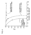
- FIG. 1 FIG. 2A Surgical Tygon 0.64 10 0 - - 0.64 20 4.4 x 10 -5 - - 0.64 30 1.1 x 10 -2 - - 0.64 45 8.8 x 10 -1 0 0 Rubber Tubing 0.64 25 1.7 x 10 -1 - - 0.64 45 7.9 x 10 -1 0 0
- the efficacy is recorded in terms of the ratio of the number of microorganisms surviving the test, S, to the number of challenge organisms, S 0 (approx. 1 x 10 6 ) on a paper strip disposed within the tube equidistant from the ends.
- S the number of microorganisms surviving the test
- S 0 the number of challenge organisms
- 100 microliters of 30% aqueous H 2 O 2 solution was supplied in each of the devices.
- the devices were attached to the ends of tubes of the indicated length and 0.64 cm in internal diameter. All of the tube samples were placed within TYVEK'/MYLAR' packaging prior to sterilization.
- the packaged tubes were placed within the sterilizing chamber and the pressure therein was reduced to about 13.33 Pa (0.1 torr) in about 10 minutes.
- Additional 30% H 2 O 2 solution was injected into the chamber to achieve a concentration of 2.0 milligrams H 2 O 2 per liter of chamber volume. Following injection of the H 2 O 2 , the tubes were retained in
- H 2 O 2 solution raised the pressure in the chamber to about 799.8 Pa (6 torr) and the pressure was again reduced to about 13.33 Pa (0.1 torr).
- low temperature gas plasma was generated in the chamber at 300 watts.
- the challenge micro organisms used in the test were Bacillus subtilis (var. globigii) spores.
- a further experiment used 7 mm medical grade Teflon tubing 183 cm in length.
- the tubing was cut into three pieces to obtain a 5 cm long center section which was joined in the end sections by external tubing connectors.
- approximately 1.0 x 10 4 Bacillus (var. globigii) spores were deposited in the center section of the Teflon tubing.
- the tubing was assembled and subjected to sterilization with hydrogen peroxide vapor as described above at a concentration of 2.0 mg./liter of chamber volume.
- the chamber was evacuated to a pressure of 13.33 Pa (0.1 torr) before the peroxide was injected as an aqueous solution and allowed to vaporize.
- a continuous gas plasma was generated in the chamber at 300 watts, 13.5 MegaHertz and the sterilization continued for an additional 5 minutes after which the vacuum was released with sterile, filtered air, and the number of surviving spores determined.
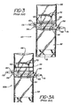
- FIGS. 3 and 3A Additional prior art devices are depicted in FIGS. 3 and 3A.
- the device shown in FIG. 3 indicated generally at 50 comprises a vessel 52 in the form of a pouch constructed of a flexible material.
- the means for connecting the vessel or pouch 52 to the end of an instrument tube comprises a first drawstring 54, and preferably a second drawstring 62. These drawstrings are preferably arranged in the configuration as shown in FIG. 2 to be drawn from opposite sides of the pouch.
- the pouch is preferably provided with an airtight seal to maintain the antimicrobial solution therein prior to use, and includes a means for creating an opening in the sealed pouch so that it may be disposed over the end of a tube.
- the seal may be created by sealing the ends 66 of the pouch, and of the lumen as often the means for opening the sealed pouch may comprise, for example, a line of weakening at 68, preferably in combination with a notch also shown generally at 68, to permit the pouch to be opened by tearing off one end.
- FIG. 3A shows a device indicated generally at 50A, similar to device 50, but wherein the airtight seal and the means for creating and opening the sealed pouch is a line of fastening 64 similar to a "zip-lock" closure.
- opening flaps 70 may be provided on either side of the pouch adjacent closure 64 of FIG. 3A, or the line of weakening 68 of FIG. 3. These flaps are firmly secured to the pouch. In use, after the sealed end 66 of the pouch of Fig. 3 has been removed along the line of weakening 68, the flaps when pulled oppositely from each other will distend the opening of the pouch for disposal around the end of an instrument tube.
- a substrate 72 such as a woven or nonwoven fabric or sponge may be disposed within the pouch for containing the antimicrobial solution.
- the drawstrings are provided with a locking means as illustrated.
- the locking means depicted at 56 at FIG. 3 comprise a catch 60 for a serrated edge 58 provided on the drawstring.
- the catch comprising an opening for disposing one end of the drawstring therethrough, is located at the opposite end of the drawstring.
- the catch may be provided by a flap, opening therein, attached to the edge of the pouch, provided the other end of the drawstring must also be attached to the pouch.
- one or both drawstrings may be provided with a locking means. By pulling the end 73 of the drawstring, the flexible pouch is gathered and a firm fastening may be made to a tube inserted within the pouch.
- a highly concentrated solution of hydrogen peroxide is used as the liquid antimicrobial in the device of the present invention.
- hydrogen peroxide can quickly cause damage to living tissue.
- a system for applying such solution to an instrument lumen while reducing the chances of accidental exposure of a user to the antimicrobial solution is highly desirable.
- the following embodiments of the present invention provide such advantage.
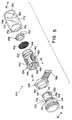
- FIG. 5 illustrates a device 100 according to the invention.
- the device 100 comprises in gross a capsule 102, an opener 104, and a safety ring 106 positioned between the capsule of 102 and the opener 104.
- the capsule 102 comprises a cylindrical body 108 having a distal end 110 and a proximal end 112. At the proximal end 112, the capsule body 108 expands radially to form a cup shaped well 114.
- a membrane wall 116 is disposed within the capsule body 108 adjacent to well 114.
- a cap 118 of generally discoidal shape has a distally projecting annular flange 120 which fits within the well 114.
- the cap 118 is sonically welded to the capsule 102 at the proximal end 112 to seal a quantity of antimicrobial solution 122 within a chamber 124 defined between the cap 118, membrane wall 116 and capsule body 108.
- the antimicrobial solution 122 may tend to diffuse through the capsule 102 and out of the chamber 124 thereby decreasing its quantity and potency.
- the antimicrobial solution 122 thus preferably comprises 197 mg of 59% hydrogen peroxide solution upon construction such that after a reasonable storage period such as ten months, the chamber 124 will retain approximately 100 mg of a 45% hydrogen peroxide solution.
- a central portion 126 of the membrane wall 116 has a slightly thinner thickness than the remainder of the membrane wall 116.
- Six radial ribs 128 extend from the capsule body 108 towards, but not into, the membrane wall central portion 126 to support the membrane wall 116 during the breaching process.
- annular flange 130 slopes outwardly and proximally, thus providing a barbed appearance in cross-section.
- the distal flange 130 preferably slopes in a gentle fashion, such as a 17° slope from an imaginary coaxial centerline 132 of the device 100.
- a central annular flange 134 slopes outwardly and proximally from the capsule body 108 at a slightly more aggressive angle than the distal flange 130.
- a pair of diametrically opposed slits 136 extend proximally in the capsule body 108 from its distal end 110 to allow some flexibility in the capsule body 108 and to thereby ease its entry into the opener 104.
- the opener 104 comprises a cylindrical body 140 having a proximal end 142 facing the capsule 102 and a distal end 144.
- a hollow spike 146 coaxially disposed within the opener body 146, extends toward the membrane wall 116 and terminates in a beveled and sharpened tip 148.
- the tip 148 is beveled at a 30° angle from the device center line 132.
- a central lumen 150 extends coaxially through the spike 146.
- Each of the posts 152 extends outwardly radially from a fixed end of the spike 146 to the opener body 140 and thereby support the spike 146 therein.
- each of the posts 152 has a distally facing fillet brace 154 for added support.
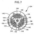
- a circumferentially interrupted annular embossment 156 extends radially inwardly in a very shallow manner from the opener body 140 (see also FIG. 7).
- a retaining ring 158 holds a mist-filter screen 160 within the opener body distal end 144.
- the mist-filter screen 160 is round with a diameter exceeding that of the opener body 140 whereby it is frictionally retained within the opener body 140 by the retaining ring 158.
- the mist-filter screen 160 has a mesh opening of 105 microns and is formed of polypropylene.
- a plurality of axially aligned embossments 162 on an outer surface of the retaining ring 158 ease insertion and securely retain the mist-filter screen 160 and retaining ring 158 within the opener body 140 (see also FIGS. 8 and 9).
- a series of detents (not shown), each with a distally facing camming surface and a proximally facing radial surface could be provided within the opener body 140, axially adjacent the posts 152.
- the mist-filter screen 160 would thus have a diameter equal to the inside diameter of the opener body 140 and be held between the posts 152 and the proximally facing surfaces of the detents.
- the screen could be easily inserted through the opener distal end 144 and cammed over the detent camming surfaces into place between the posts 152 and detents.
- the safety ring 106 separates the opener 104 from the capsule 102. With the safety ring 106 trapped between the opener body proximal end 142 and the lip 115 on the capsule 102, the spike 146 is prevented from contacting the membrane wall 116 (see also FIG. 8).
- the safety ring 106 is provided with a thin wall section 164 and a diametrically opposed pull tab 166 whereby manual pressure applied to the pull tab 166 is sufficient to deform the thin wall section 164 beyond its elastic limit, preferably breaching the thin wall section 164, thereby permitting removal of the safety ring 106 from the device 100.
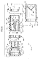
- FIG. 8 illustrates the assembled device 100 prior to use, with an adapter 170 affixed thereto.
- the adapter 170 comprises a cylindrical tubular body 172 formed of a soft thermoplastic elastomer, such as Schafer, GmbH THEKA-FLEX, S 2030 M.
- a shallow inwardly facing annular flange 174 at a proximal end 176 of the adapter body 172 is received within a correspondingly shallow annular groove about the opener body 140 to hold the adapter 170 to the device 100.
- a truncated cone 178 extends inwardly, proximally, from a distal end 180 of the adapter body 172 and terminates in a central opening 182.
- the dimensions of the cone 178 can be varied to accommodate various types of instruments to be sterilized and that other engaging means may be substituted therefor.
- an appropriately sized adapter 170 is selected for the particular instrument 186 to be sterilized.
- the adapter 170 is attached to the device 100 as shown in FIG. 8.
- the pull-tab 166 on the safety ring 106 is grasped and pulled to separate the safety ring thin wall section 164 and remove the safety ring 106 from the device 100.
- the opener body 140 is provided with several textured finger indentations 190 for easier grasping.
- the capsule 102 and opener 104 are pushed together so that the spike 146 breaches the membrane wall 116 as shown in FIG. 9.
- the capsule 102 is then rotated one full turn to ensure proper breaching of the membrane wall 116.
- the antimicrobial 122 is then free to leave the chamber 124 and flow into the instrument lumen 188.
- the device 100 with adapter 172 and instrument 186 attached as the membrane wall breached 116 as shown in FIG. 9 are then placed into the sterilization chamber (not shown ) of a solution vapor sterilizer (also not shown).
- a vacuum applied to the sterilization chamber causes the antimicrobial 122 to vaporize and migrate into the instrument lumen 188 to effect sterilization thereof.
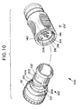
- FIGS. 10 to 13 illustrate a further embodiment of a device 200 according to the invention.
- the device 200 is similar in nearly all respects to the device 100 with the exception of the following differences. Accordingly, portions of the device 200 which are identical to the device 100 and were previously described with respect thereto, will be designated with like referenced numerals having a prime symbol (').
- a raised embossment 202 surrounds the capsule body 108' adjacent the lip 115'.
- a pair of threads 204 formed in the embossment 202 receive, respectfully, a pair of pins 206 which project into the opener body 140'.
- Each thread 204 comprises a camming portion 208 and a circumferential portion 210.
- the pins 206 enter the threads 204 through the camming portions 208 as the capsule 102' is rotated relative to the opener 104', thereby pulling the capsule 102' axially into the opener 104'.
- the circumferential portion 210 of the threads 204 allows the capsule 102' to be rotated an additional one quarter turn after it is fully received within the opener 104' to insure proper breaching of the membrane wall 116'.
- the interaction of the central flange 134 and the opener body 140 seals the capsule 102 to the opener 104 to prevent antimicrobial 122 from leaking out of the device 100 between the capsule 102 and opener 104.
- an O-ring 212 about the capsule body 108' replaces the central flange 136 and engages the opener body 140' to seal the capsule 102' therein.
- the spike 146 is provided with a simple bevelled tip 148 to penetrate the membrane wall 116.
- the bevelled tip 148 is replaced by a cutting tip 214 which is placed off of the central axles of the spike 146' and which acts in a fashion similar to that of a can opener to cut open the membrane wall 116.
- the cutting tip 214 may take various forms, however a sharp apex 216 and a sharp leading cutting edge 218 improve its cutting ability.
- the threading interaction between the capsule 102' and opener 104' breaches the membrane wall 116' more gently than in the previous embodiment.
- the user receives less tactile feedback that the membrane wall 116' has been breached. It may be desirable to provide such feedback in the form of a snapping interaction between parts on the capsule 102' and opener 104' or perhaps to provide a visual indication or other feedback that the opener 104' is fully actuated.
- FIGS. 12 and 13 illustrate one method of providing such feedback.
- each pins 206 travels its respective thread circumferential portion 210, it encounters a detent 220.
- the pins 206 cam over the detents 220 and snap over a sharp trailing edge 222 thereon to become trapped beyond the detents 220.
- the detents 220 provide both an audible and tactile feedback that the proper interaction has been achieved between the capsule 102' and opener 104'. Further, they prevent the capsule 102' and opener 104', and further prevent the capsule 102' from being easily backed out of the opener 104'. Alignment marks (not shown) or other visual indicia mark also be provided on the capsule 102' and opener 104' to indicate full actuation.
Landscapes
- Health & Medical Sciences (AREA)
- Life Sciences & Earth Sciences (AREA)
- Animal Behavior & Ethology (AREA)
- General Health & Medical Sciences (AREA)
- Public Health (AREA)
- Veterinary Medicine (AREA)
- Epidemiology (AREA)
- General Chemical & Material Sciences (AREA)
- Chemical Kinetics & Catalysis (AREA)
- Chemical & Material Sciences (AREA)
- Surgery (AREA)
- Physics & Mathematics (AREA)
- Engineering & Computer Science (AREA)
- Nuclear Medicine, Radiotherapy & Molecular Imaging (AREA)
- Pathology (AREA)
- Radiology & Medical Imaging (AREA)
- Optics & Photonics (AREA)
- Biophysics (AREA)
- Biomedical Technology (AREA)
- Heart & Thoracic Surgery (AREA)
- Medical Informatics (AREA)
- Molecular Biology (AREA)
- Plasma & Fusion (AREA)
- Apparatus For Disinfection Or Sterilisation (AREA)
Claims (15)
- Vorrichtung (100; 200) zum Überführen eines antimikrobiellen Dampfes in einen Hohlraum (188) eines Gegenstandes (186) während einer Lösungsdampfsterilisation, wobei die Vorrichtung umfasst:ein erstes Teil (102; 102'), das einen Behälter mit einer inneren, abgedichteten Kammer (124), die eine antimikrobielle Lösung (122) enthält, und eine Wand (116), die zumindest einen Abschnitt der Kammer bildet, aufweist;ein Verbindungsteil (170), das mit der Wand in Verbindung steht, um den Behälter mit dem Hohlraum (188) des Gegenstandes zu verbinden;ein zweites Teil (104; 104'), das mit dem ersten Teil (102; 102') relativ zu diesem bewegbar verbunden ist, wobei das zweite Teil (104; 104') ein Öffnungsteil (146) aufweist und wobei eine Bewegung des zweiten Teils (104; 104') in eine vorbestimmte Richtung relativ zu dem ersten Teil (102; 102') das Öffnungsteil (146) in Richtung der Wand (116) bewegt, um die Wand (116) zu öffnen und die Kammer mit dem Hohlraum (118) des Gegenstands in Fluidverbindung zu bringen; dadurch gekennzeichnet, dass die Vorrichtung weiterhin umfasst:eine erste Anschlagfläche (115; 115') auf dem ersten Teil;eine zweite Anschlagfläche (142) auf dem zweiten Teil; undein entfembares Schutzelement (106) zwischen der ersten und der zweiten Anschlagfläche, das ein Aufeinanderzubewegen des ersten Teils und des zweiten Teils, das ausreichend ist, die Wand zu durchbrechen, verhindert, wobei das entfembare Schutzelement einen Sicherheitsring (106) aufweist, der die Vorrichtung zwischen dem ersten Teil unddem zweiten Teil umschließt und der um diese herum einen dünnen Wandabschnitt (164) und eine Zuglasche (166) aufweist, wobei ein auf die Zuglasche (166) ausgeübter manueller Druck eine Verformung des dünnen Wandabschnittes verursacht und das Entfernen des Sicherheitsringes (106) von der Vorrichtung ermöglicht.
- Vorrichtung nach Anspruch 1, dadurch gekennzeichnet, dass das erste Teil und das zweite Teil teleskopartig miteinander verbunden sind.
- Vorrichtung nach Anspruch 1 oder 2, dadurch gekennzeichnet, dass die Vorrichtung weiterhin einen ersten Anschlag (130) auf einem der ersten und zweiten Teile und eine erste Oberfläche (156) auf dem anderen der ersten und zweiten Teile umfasst, wobei der erste Anschlag mit der ersten Oberfläche zusammenwirkt, um das Ausmaß zu begrenzen, bis zu dem das erste Teil und das zweite Teil teleskopartig auseinander geschoben werden können.
- Vorrichtung nach einem der vorhergehenden Ansprüche, dadurch gekennzeichnet, dass das Öffnungsteil einen Dorn (146) aufweist, der innerhalb des zweiten Teiles in einer Position aufgenommen ist, um die Wand zu durchbrechen, wenn das erste Teil und das zweite Teil ineinander geschoben werden.
- Vorrichtung nach Anspruch 4, dadurch gekennzeichnet, dass der Dom weiterhin ein erstes Ende (148, 214), das der Wand zugewandt ist, ein zweites Ende und einen zentralen Hohlraum (150), der sich koaxial durch denselben erstreckt, umfasst, wobei der Hohlraum des Domes ein erstes Ende an dem ersten Ende des Domes und ein zweites Ende aufweist und wobei das zweite Ende des Hohlraumes des Domes mit dem Verbindungsteil in Fluidverbindung steht, wodurch der Behälter in Fluidverbindung mit dem Hohlraum des Gegenstandes durch den Hohlraum des Domes steht, wenn der Dorn die Wand durchdringt.
- Vorrichtung nach einem der vorhergehenden Ansprüche, dadurch gekennzeichnet, dass die Vorrichtung weiterhin einen Dunstfilter (60) in dem zweiten Teil zwischen dem ersten Teil und dem Verbindungsteil aufweist, um zu verhindern, dass eine flüssige, antimikrobielle Lösung oder Fremdkörper in den Hohlraum des Gegenstandes gelangen.
- Vorrichtung nach einem der vorhergehenden Ansprüche, dadurch gekennzeichnet, dass die Wand eine Membran mit einem dünneren, zentralen Abschnitt aufweist.
- Vorrichtung nach einem der vorhergehenden Ansprüche, dadurch gekennzeichnet, dass sich radiale Rippen (128) von der Innenwand des ersten Teiles in Richtung eines zentralen Wandabschnittes (126), aber nicht in diesen hinein erstrecken, um die Wand (116) während des Öffnens der Wand durch das Öffnungsteil (146) abzustützen.
- Vorrichtung nach einem der vorhergehenden Ansprüche, dadurch gekennzeichnet, dass das erste Teil und das zweite Teil beim Öffnen der Wand durch einen Eingriff entweder eines O-Ringes (212) oder eines zentralen, ringförmigen Flansches (134) auf dem ersten Teil in eine innere Wand des zweiten Teiles abdichtend miteinander verbunden sind.
- Vorrichtung nach einen der vorhergehenden Ansprüche, dadurch gekennzeichnet, dass sich ein Paar von sich diametral gegenüberliegenden Schlitzen (136) proximal in dem ersten Teil ausgehend von seinem distalen Ende (110) erstreckt, um die Verbindung des ersten Teiles in dem zweiten Teil zu lockern.
- Vorrichtung nach einem der vorhergehenden Ansprüche, dadurch gekennzeichnet, dass Eingriffsmittel (178) für das Verbindungsteil zum Abdichten eines Endes eines Hohlraumes (188) eines Gegenstandes (186) in dem Verbindungsteil vorhanden sind.
- Vorrichtung nach einem der vorherigen Ansprüche, dadurch gekennzeichnet, dass die Vorrichtung weiterhin eine Gewindeverbindung (204; 206) zwischen dem ersten Teil und dem zweiten Teil umfasst, wobei eine Drehung des ersten und des zweiten Teils relativ zueinander diese beiden Teile aufeinander zu bewegt, um die Wand zu durchbrechen.
- Vorrichtung nach Anspruch 12, dadurch gekennzeichnet, dass die Gewinde (204) der Gewindeverbindung einen Schiebeabschnitt (208) und einen umlaufenden Abschnitt (210) aufweisen, wobei der umlaufende Abschnitt (210) ermöglicht, dass das zweite Teil bezüglich des ersten Teiles zusätzlich um eine Vierteldrehung gedreht werden kann, nachdem die beiden Teile unter Verwendung des Schiebeabschnittes zusammenbewegt worden sind.
- Vorrichtung nach Anspruch 12 oder 13, dadurch gekennzeichnet, dass ein Anschlag in der Gewindeverbindung zur Verwendung als hör- und fühlbares Feedback, dass die Wand geöffnet worden ist, vorhanden ist.
- Vorrichtung nach einem der vorhergehenden Ansprüche, dadurch gekennzeichnet, dass der erste Anschlag auf einem distalen Ende (110) des ersten Teiles angeordnet ist und einen ringförmigen Flansch (130) aufweist, der nach außen und proximal abfällt, und dass der zweite Anschlag eine in Umfangsrichtung verlaufende, unterbrochene Ringwulst (156) ist, die sich von einer Innenwand des zweiten Teiles nach innen erstreckt.
Priority Applications (2)
| Application Number | Priority Date | Filing Date | Title |
|---|---|---|---|
| EP03078199A EP1380309B1 (de) | 1995-05-08 | 1996-05-07 | Vorrichtung zur Dampfsterilisation von Erzeugnissen mit Lumen |
| EP05075712A EP1552853A3 (de) | 1995-05-08 | 1996-05-07 | Gerät zur Dampfsterilisation von Erzeugnissen mit Lumen |
Applications Claiming Priority (2)
| Application Number | Priority Date | Filing Date | Title |
|---|---|---|---|
| US436999 | 1995-05-08 | ||
| US08/436,999 US5580530A (en) | 1987-07-30 | 1995-05-08 | Device for vapor sterilization of articles having lumens |
Related Child Applications (1)
| Application Number | Title | Priority Date | Filing Date |
|---|---|---|---|
| EP03078199A Division EP1380309B1 (de) | 1995-05-08 | 1996-05-07 | Vorrichtung zur Dampfsterilisation von Erzeugnissen mit Lumen |
Publications (3)
| Publication Number | Publication Date |
|---|---|
| EP0742017A2 EP0742017A2 (de) | 1996-11-13 |
| EP0742017A3 EP0742017A3 (de) | 1998-01-14 |
| EP0742017B1 true EP0742017B1 (de) | 2004-02-18 |
Family
ID=23734650
Family Applications (3)
| Application Number | Title | Priority Date | Filing Date |
|---|---|---|---|
| EP96303167A Expired - Lifetime EP0742017B1 (de) | 1995-05-08 | 1996-05-07 | Dampfsterilisation von Erzeugnissen mit Lumen |
| EP03078199A Expired - Lifetime EP1380309B1 (de) | 1995-05-08 | 1996-05-07 | Vorrichtung zur Dampfsterilisation von Erzeugnissen mit Lumen |
| EP05075712A Withdrawn EP1552853A3 (de) | 1995-05-08 | 1996-05-07 | Gerät zur Dampfsterilisation von Erzeugnissen mit Lumen |
Family Applications After (2)
| Application Number | Title | Priority Date | Filing Date |
|---|---|---|---|
| EP03078199A Expired - Lifetime EP1380309B1 (de) | 1995-05-08 | 1996-05-07 | Vorrichtung zur Dampfsterilisation von Erzeugnissen mit Lumen |
| EP05075712A Withdrawn EP1552853A3 (de) | 1995-05-08 | 1996-05-07 | Gerät zur Dampfsterilisation von Erzeugnissen mit Lumen |
Country Status (13)
| Country | Link |
|---|---|
| US (2) | US5580530A (de) |
| EP (3) | EP0742017B1 (de) |
| JP (1) | JP4330664B2 (de) |
| KR (1) | KR100443600B1 (de) |
| AR (1) | AR001878A1 (de) |
| AU (1) | AU700172B2 (de) |
| BR (1) | BR9602186B1 (de) |
| CA (1) | CA2175867C (de) |
| DE (2) | DE69635595T2 (de) |
| ES (2) | ES2213766T3 (de) |
| IN (1) | IN189443B (de) |
| NZ (1) | NZ286537A (de) |
| ZA (1) | ZA963598B (de) |
Cited By (2)
| Publication number | Priority date | Publication date | Assignee | Title |
|---|---|---|---|---|
| US10814027B2 (en) | 2017-12-07 | 2020-10-27 | Asp Global Manufacturing Gmbh | Sterilization-assistance device |
| US10967084B2 (en) | 2017-12-15 | 2021-04-06 | Asp Global Manufacturing Gmbh | Flow restrictor |
Families Citing this family (125)
| Publication number | Priority date | Publication date | Assignee | Title |
|---|---|---|---|---|
| US5580530A (en) * | 1987-07-30 | 1996-12-03 | Johnson & Johnson Medical, Inc. | Device for vapor sterilization of articles having lumens |
| US6495100B1 (en) | 1996-04-04 | 2002-12-17 | Ethicon, Inc. | Method for sterilizing devices in a container |
| US6030579A (en) * | 1996-04-04 | 2000-02-29 | Johnson & Johnson Medical, Inc. | Method of sterilization using pretreatment with hydrogen peroxide |
| US6325972B1 (en) * | 1998-12-30 | 2001-12-04 | Ethicon, Inc. | Apparatus and process for concentrating a liquid sterilant and sterilizing articles therewith |
| US5871692A (en) * | 1997-01-14 | 1999-02-16 | Steris Corporation | Method and apparatus for cleaning, decontaminating, and sterilizing catheters |
| US6528017B2 (en) | 1997-04-04 | 2003-03-04 | Ethicon, Inc. | System and method for sterilizing a lumen device |
| US6977061B2 (en) * | 1997-04-04 | 2005-12-20 | Ethicon Endo-Surgery, Inc. | Method and apparatus for sterilizing a lumen device |
| GR1003266B (en) * | 1997-05-05 | 1999-12-02 | Christos Georgiou | Specific device for the cultivation of organisms in liquid nutritional materials inside differetn types of dishes |
| US6203756B1 (en) | 1997-12-17 | 2001-03-20 | Johnson & Johnson Medical, Inc. | Integrated cleaning sterilization process |
| US7556767B2 (en) | 1997-12-17 | 2009-07-07 | Ethicon, Inc. | Integrated washing and sterilization process |
| US7803316B2 (en) * | 1997-08-21 | 2010-09-28 | Ethicon, Inc. | Method and apparatus for processing a lumen device |
| US20010031221A1 (en) * | 1997-12-17 | 2001-10-18 | Wu Su-Syin S. | Apparatus and method for delivering fluids to contact surfaces between parts of a medical device |
| US6451255B1 (en) | 1997-08-21 | 2002-09-17 | Ethicon, Inc. | Dry booster |
| US7229591B2 (en) * | 1997-08-21 | 2007-06-12 | Ethicon, Inc. | Lumen sterilization device and method |
| US6815206B2 (en) * | 1997-09-19 | 2004-11-09 | Ethicon, Inc. | Container monitoring system |
| US6015529A (en) * | 1997-12-17 | 2000-01-18 | Johnson & Johnson Medical, Inc. | Tray/container system for cleaning/sterilization processes |
| US6645430B1 (en) | 1997-12-17 | 2003-11-11 | Ethicon, Inc. | Method and apparatus for processing device with fluid submersion |
| US6083458A (en) * | 1997-12-17 | 2000-07-04 | Ethicon, Inc. | Apparatus and method for providing fluid to devices with reduced or without occlusion |
| JP4948692B2 (ja) * | 1997-12-17 | 2012-06-06 | エシコン・インコーポレイテッド | 接触面を有する物品へ殺菌薬剤を供給する装置および方法 |
| US6596232B1 (en) | 1997-12-17 | 2003-07-22 | Ethicon, Inc. | Device processing apparatus and method having positive pressure with two partitions to minimize leakage |
| US6013227A (en) * | 1997-12-17 | 2000-01-11 | Johnson & Johnson Medical, Inc. | Lumen device reprocessor without occlusion |
| US6685895B1 (en) | 1997-12-17 | 2004-02-03 | Ethicon, Inc. | Method and apparatus for processing device with reduced occlusion |
| US6187266B1 (en) | 1997-12-17 | 2001-02-13 | Johnson & Johnson Medical, Inc. | Integrated cleaning/sterilization process with lumen devices |
| US5868667A (en) * | 1998-03-27 | 1999-02-09 | Ethicon, Inc. | Pressure-equalizing cap |
| US5932482A (en) * | 1998-08-10 | 1999-08-03 | Markelov; Michael | Headspace vial apparatus and method |
| US6312646B2 (en) | 1998-08-17 | 2001-11-06 | Enviromedical Systems, Inc. | Sterilization of elongate lumens |
| AU6273899A (en) | 1998-10-01 | 2000-04-17 | Minntech Corporation | Reverse flow cleaning and sterilizing device and method |
| AU1827600A (en) | 1998-11-23 | 2000-06-13 | Ecolab Inc. | Non-corrosive sterilant composition |
| DE69938259T2 (de) | 1998-12-30 | 2009-02-26 | Ethicon Inc. | Sterile verpackung für flexible endoskope |
| US6312645B1 (en) * | 1998-12-30 | 2001-11-06 | Ethicon, Inc. | Container with collapsible pouch for cleaning or sterilization |
| US6534002B1 (en) | 1998-12-30 | 2003-03-18 | Ethicon, Inc. | Flow of fluid through a lumen device from smaller-caliber end to larger-caliber end |
| US6767509B1 (en) | 1999-06-16 | 2004-07-27 | Kimberly-Clark Worldwide, Inc. | Self-sterilizing packaging |
| JP2003530489A (ja) | 1999-12-28 | 2003-10-14 | キンバリー クラーク ワールドワイド インコーポレイテッド | 放出制御抗菌剤を含むワイプ |
| JP2003527168A (ja) | 1999-12-28 | 2003-09-16 | キンバリー クラーク ワールドワイド インコーポレイテッド | 硬い表面に用いる放出制御抗菌ワイプ |
| US6794318B2 (en) | 1999-12-28 | 2004-09-21 | Kimberly-Clark Worldwide, Inc. | Use-dependent indicator system for absorbent articles |
| US6599441B1 (en) * | 2000-07-18 | 2003-07-29 | Emerald Biostructures, Inc. | Crystallization solutions |
| ATE297225T1 (de) | 2001-02-16 | 2005-06-15 | Steris Inc | Dekontamination von behältern mit dampf |
| US7803315B2 (en) | 2001-10-05 | 2010-09-28 | American Sterilizer Company | Decontamination of surfaces contaminated with prion-infected material with gaseous oxidizing agents |
| CN1639575A (zh) * | 2001-10-05 | 2005-07-13 | 斯特里斯公司 | 用于抗朊病毒活性的体外模型 |
| DE10209124A1 (de) * | 2002-03-01 | 2003-10-16 | Wolf Gmbh Richard | Absaugventil für ein Endoskop |
| US6919057B2 (en) * | 2002-04-04 | 2005-07-19 | Steris Inc. | Automated endoscope reprocessor |
| US7351386B2 (en) | 2002-04-04 | 2008-04-01 | Steris Inc | Cartridge holder for automated reprocessor |
| US7300637B2 (en) * | 2002-09-30 | 2007-11-27 | Ethicon, Inc. | Sterilization container kit |
| US7071152B2 (en) * | 2003-05-30 | 2006-07-04 | Steris Inc. | Cleaning and decontamination formula for surfaces contaminated with prion-infected material |
| US20050147524A1 (en) * | 2004-01-06 | 2005-07-07 | Bousquet Gerald G. | Sterile tubing termination assembly |
| JP4422501B2 (ja) * | 2004-01-21 | 2010-02-24 | オリンパス株式会社 | 内視鏡及び内視鏡システム |
| US8641684B2 (en) * | 2005-10-11 | 2014-02-04 | Nxstage Medical, Inc. | Closure for tubular access port |
| US8361408B2 (en) * | 2006-03-16 | 2013-01-29 | Lawrence Allan Lynn | Luer protection pouch and luer valve/male luer protection method |
| US20080039803A1 (en) * | 2006-08-09 | 2008-02-14 | Lawrence Allan Lynn | Luer protection pouch™ and luer valve/male luer protection method |
| US9592375B2 (en) | 2006-05-18 | 2017-03-14 | Hyprotek, Inc. | Intravascular line and port cleaning methods, methods of administering an agent intravascularly, methods of obtaining/testing blood, and devices for performing such methods |
| US8162899B2 (en) | 2006-05-18 | 2012-04-24 | Hyprotek, Inc. | Intravascular line and port cleaning methods, methods of administering an agent intravascularly, methods of obtaining/testing blood, and devices for performing such methods |
| US8167847B2 (en) | 2006-06-22 | 2012-05-01 | Excelsior Medical Corporation | Antiseptic cap and antiseptic cap equipped plunger and syringe barrel assembly |
| US9700710B2 (en) | 2006-06-22 | 2017-07-11 | Excelsior Medical Corporation | Antiseptic cap equipped syringe |
| US9259535B2 (en) | 2006-06-22 | 2016-02-16 | Excelsior Medical Corporation | Antiseptic cap equipped syringe |
| US11229746B2 (en) | 2006-06-22 | 2022-01-25 | Excelsior Medical Corporation | Antiseptic cap |
| US12377251B2 (en) | 2006-11-27 | 2025-08-05 | Frank Levy | Apparatus and method for producing an enriched medical suspension of carbon dioxide |
| US10155093B2 (en) | 2006-11-27 | 2018-12-18 | Frank Levy | Apparatus and method for producing CO2 enriched medical foam |
| US11185671B2 (en) | 2006-11-27 | 2021-11-30 | Frank Levy | Apparatus and process for producing CO2 enriched medical foam |
| US9651197B2 (en) * | 2006-11-27 | 2017-05-16 | Frank Levy | Disposable cartridge for holding compressed medical gas |
| US10322271B2 (en) | 2006-11-27 | 2019-06-18 | Frank Levy | Delivery system and method for the effective and reliable delivery of controlled amounts of a medical fluid |
| US11833320B2 (en) | 2006-11-27 | 2023-12-05 | Frank Levy | Apparatus and process for producing CO2 enriched medical foam |
| US10350399B2 (en) | 2006-11-27 | 2019-07-16 | Frank Levy | Apparatus and method for producing an enriched medical suspension of carbon dioxide |
| JP2008272113A (ja) * | 2007-04-26 | 2008-11-13 | Olympus Medical Systems Corp | 内視鏡洗浄消毒装置 |
| JP5095009B2 (ja) * | 2008-06-09 | 2012-12-12 | ベクトン・ディキンソン・フランス・エス.エー.エス. | 滅菌パッケージ及びこのパッケージを用いた滅菌方法 |
| US9849276B2 (en) | 2011-07-12 | 2017-12-26 | Pursuit Vascular, Inc. | Method of delivering antimicrobial to a catheter |
| US9078992B2 (en) | 2008-10-27 | 2015-07-14 | Pursuit Vascular, Inc. | Medical device for applying antimicrobial to proximal end of catheter |
| US8889081B2 (en) | 2009-10-15 | 2014-11-18 | Medivators Inc. | Room fogging disinfection system |
| EP2506884B1 (de) | 2009-12-03 | 2015-02-18 | Minntech Corporation | Behälter zur dekontaminierung eines medizinischen geräts mit nebel |
| US9475709B2 (en) | 2010-08-25 | 2016-10-25 | Lockheed Martin Corporation | Perforated graphene deionization or desalination |
| GB2483741A (en) * | 2010-09-15 | 2012-03-21 | Medicart Int Ltd | Conditioning medical equipment |
| US8840836B2 (en) | 2011-04-27 | 2014-09-23 | Sterilucent, Inc. | Sterilization method with compression and expansion |
| WO2012162259A2 (en) | 2011-05-20 | 2012-11-29 | Excelsior Medical Corporation | Caps for cannula access devices |
| US9867975B2 (en) | 2011-05-23 | 2018-01-16 | Excelsior Medical Corporation | Antiseptic line cap |
| US10166381B2 (en) | 2011-05-23 | 2019-01-01 | Excelsior Medical Corporation | Antiseptic cap |
| CN103702689B (zh) | 2011-05-27 | 2016-08-17 | 马尔科尔净化装置公司 | 包括使用净化物质的环境控制的净化系统 |
| EP2758097A4 (de) | 2011-09-21 | 2015-07-01 | Bayer Medical Care Inc | Kontinuierliche multi-fluid-pumpvorrichtung, antrieb sowie betätigungssystem und -verfahren dafür |
| JP5899776B2 (ja) * | 2011-10-06 | 2016-04-06 | キヤノンマーケティングジャパン株式会社 | 携帯滅菌装置。 |
| JP5772699B2 (ja) * | 2012-04-20 | 2015-09-02 | キヤノンマーケティングジャパン株式会社 | 滅菌補助装置および滅菌処理方法 |
| US9610546B2 (en) | 2014-03-12 | 2017-04-04 | Lockheed Martin Corporation | Separation membranes formed from perforated graphene and methods for use thereof |
| US10653824B2 (en) | 2012-05-25 | 2020-05-19 | Lockheed Martin Corporation | Two-dimensional materials and uses thereof |
| US9834809B2 (en) | 2014-02-28 | 2017-12-05 | Lockheed Martin Corporation | Syringe for obtaining nano-sized materials for selective assays and related methods of use |
| US10376845B2 (en) | 2016-04-14 | 2019-08-13 | Lockheed Martin Corporation | Membranes with tunable selectivity |
| US9744617B2 (en) | 2014-01-31 | 2017-08-29 | Lockheed Martin Corporation | Methods for perforating multi-layer graphene through ion bombardment |
| US10213746B2 (en) | 2016-04-14 | 2019-02-26 | Lockheed Martin Corporation | Selective interfacial mitigation of graphene defects |
| JP5803850B2 (ja) * | 2012-08-29 | 2015-11-04 | キヤノンマーケティングジャパン株式会社 | 滅菌補助具および滅菌処理方法 |
| WO2014164621A1 (en) | 2013-03-12 | 2014-10-09 | Lockheed Martin Corporation | Method for forming filter with uniform aperture size |
| US9572918B2 (en) | 2013-06-21 | 2017-02-21 | Lockheed Martin Corporation | Graphene-based filter for isolating a substance from blood |
| US10022189B2 (en) | 2013-12-16 | 2018-07-17 | Stryker Sustainability Solutions, Inc. | Apparatus and method for cleaning an instrument |
| WO2015116946A1 (en) | 2014-01-31 | 2015-08-06 | Lockheed Martin Corporation | Perforating two-dimensional materials using broad ion field |
| SG11201606287VA (en) | 2014-01-31 | 2016-08-30 | Lockheed Corp | Processes for forming composite structures with a two-dimensional material using a porous, non-sacrificial supporting layer |
| CN106232205A (zh) | 2014-03-12 | 2016-12-14 | 洛克希德马丁公司 | 由有孔石墨烯形成的分离膜 |
| ES2755352T3 (es) | 2014-05-02 | 2020-04-22 | Excelsior Medical Corp | Paquete en tira para tapón antiséptico |
| CN105179837B (zh) | 2014-06-03 | 2019-11-05 | 机械工业股份公司 | 用于运送气体、压缩空气、和其他流体的导管的连接接头 |
| MX2017002738A (es) | 2014-09-02 | 2017-08-02 | Lockheed Corp | Membranas de hemodialisis y hemofiltracion basadas en un material de membrana bidimensional y metodos que emplean las mismas. |
| EP4628145A3 (de) | 2015-01-09 | 2025-12-03 | Bayer Healthcare LLC | System zur abgabe mehrerer flüssigkeiten mit einwegset zur mehrfachverwendung und funktionen davon |
| US10279060B2 (en) * | 2015-04-28 | 2019-05-07 | Medivators Inc. | System for decontamination of a lumen device |
| DK3294404T3 (da) | 2015-05-08 | 2025-09-08 | Icu Medical Inc | Medicinske konnektorer konfigureret til at modtage emittere af terapeutiske midler |
| WO2017023376A1 (en) | 2015-08-05 | 2017-02-09 | Lockheed Martin Corporation | Perforatable sheets of graphene-based material |
| JP2018530499A (ja) | 2015-08-06 | 2018-10-18 | ロッキード・マーチン・コーポレーション | グラフェンのナノ粒子変性及び穿孔 |
| US10330228B2 (en) | 2015-08-31 | 2019-06-25 | Ingersoll-Rand Company | Pipe connection fitting |
| CN108883222B (zh) * | 2016-02-01 | 2023-01-17 | 利比迪公司 | 具有连接器的透析系统泵 |
| KR20190018410A (ko) | 2016-04-14 | 2019-02-22 | 록히드 마틴 코포레이션 | 흐름 통로들을 갖는 2차원 막 구조들 |
| EP3442739A4 (de) | 2016-04-14 | 2020-03-04 | Lockheed Martin Corporation | Verfahren zur behandlung von graphenfolien für grossflächigen transfer mittels free-float-verfahren |
| WO2017180134A1 (en) | 2016-04-14 | 2017-10-19 | Lockheed Martin Corporation | Methods for in vivo and in vitro use of graphene and other two-dimensional materials |
| KR20180133430A (ko) | 2016-04-14 | 2018-12-14 | 록히드 마틴 코포레이션 | 결함 형성 또는 힐링의 인 시츄 모니터링 및 제어를 위한 방법 |
| JP2018008001A (ja) * | 2016-06-30 | 2018-01-18 | キヤノンマーケティングジャパン株式会社 | 滅菌補助具 |
| EP3278719A1 (de) * | 2016-08-01 | 2018-02-07 | Cantel Medical (UK) Limited | Universeller endoskoptrockenschrank |
| PL3525865T3 (pl) | 2016-10-14 | 2023-02-06 | Icu Medical, Inc. | Nasadki dezynfekcyjne dla łączników medycznych |
| US11298437B2 (en) | 2016-11-15 | 2022-04-12 | Ideate Medical | Apparatus and method for sterilization of an article |
| MX2019008791A (es) | 2017-02-01 | 2019-09-26 | Liberdi Ltd | Dispositivo inteligente para dialisis peritoneal. |
| WO2018204206A2 (en) | 2017-05-01 | 2018-11-08 | Icu Medical, Inc. | Medical fluid connectors and methods for providing additives in medical fluid lines |
| WO2019195723A1 (en) | 2018-04-06 | 2019-10-10 | Frank Levy | Apparatus and method for producing an enriched medical contrast suspension |
| CA3095939C (en) | 2018-04-06 | 2023-09-26 | Frank Levy | Apparatus and method for producing an enriched medical suspension |
| JP6957770B2 (ja) * | 2018-10-25 | 2021-11-02 | オリンパス株式会社 | 内視鏡アタッチメントおよび内視鏡システム |
| US11400195B2 (en) | 2018-11-07 | 2022-08-02 | Icu Medical, Inc. | Peritoneal dialysis transfer set with antimicrobial properties |
| US11534595B2 (en) | 2018-11-07 | 2022-12-27 | Icu Medical, Inc. | Device for delivering an antimicrobial composition into an infusion device |
| US11517732B2 (en) | 2018-11-07 | 2022-12-06 | Icu Medical, Inc. | Syringe with antimicrobial properties |
| US11541221B2 (en) | 2018-11-07 | 2023-01-03 | Icu Medical, Inc. | Tubing set with antimicrobial properties |
| US11541220B2 (en) | 2018-11-07 | 2023-01-03 | Icu Medical, Inc. | Needleless connector with antimicrobial properties |
| JP2022513096A (ja) | 2018-11-21 | 2022-02-07 | アイシーユー・メディカル・インコーポレーテッド | リング及びインサートを有するキャップを備える抗菌装置 |
| WO2021242853A1 (en) * | 2020-05-26 | 2021-12-02 | Gyrus Acmi, Inc. D/B/A Olympus Surgical Technologies America | Endoscope with variable flexibility |
| JP2024500319A (ja) | 2020-12-07 | 2024-01-09 | アイシーユー・メディカル・インコーポレーテッド | 腹膜透析キャップ、システム、及び方法 |
| US20220257807A1 (en) * | 2021-02-12 | 2022-08-18 | Sanfilippo Tech, Llc. | Sterilization unit and methods of using the same |
| CA3221376A1 (en) | 2021-05-26 | 2022-12-01 | Ideate Medical, Inc. | Port connectors |
| US12409271B2 (en) | 2022-04-25 | 2025-09-09 | Frank Levy | Apparatus and method for producing an enriched medical suspension |
Family Cites Families (35)
| Publication number | Priority date | Publication date | Assignee | Title |
|---|---|---|---|---|
| US1817530A (en) * | 1927-07-26 | 1931-08-04 | Abraham N Spanel | Means for treating articles |
| US2688428A (en) * | 1950-01-19 | 1954-09-07 | Worcester Pressed Steel Compan | Stored pressure medium container |
| US3371985A (en) * | 1964-09-16 | 1968-03-05 | Edward W. Wyka | Vaporizer device |
| US3688985A (en) * | 1970-12-09 | 1972-09-05 | Walter H Engel | Plastic article of manufacture impregnated with volatile matter |
| US3730434A (en) * | 1972-06-21 | 1973-05-01 | W Engel | Space volatilizing device |
| US4169123A (en) * | 1975-12-11 | 1979-09-25 | Moore-Perk Corporation | Hydrogen peroxide vapor sterilization method |
| US4152378A (en) * | 1977-03-14 | 1979-05-01 | Baxter Travenol Laboratories, Inc. | Container closure having automatic opening means |
| US4239414A (en) * | 1979-11-19 | 1980-12-16 | Williamson Charles H | Bracket for attaching rails to steel fence posts |
| US4337223A (en) * | 1981-02-13 | 1982-06-29 | Ben Venue Laboratories, Inc. | Sterilizing apparatus incorporating recirculation of chamber atmosphere |
| US4410492A (en) * | 1981-02-13 | 1983-10-18 | Ben Venue Laboratories, Inc. | Sterilizing method incorporating recirculation of chamber atmosphere |
| US4380530A (en) * | 1981-02-13 | 1983-04-19 | Ben Venue Laboratories, Inc. | Sterilizer with inflatable article holder |
| US4526623A (en) * | 1983-04-15 | 1985-07-02 | Olympus Optical Co., Ltd. | Method of cleaning endoscope channels |
| US4526622A (en) * | 1983-04-15 | 1985-07-02 | Olympus Optical Co., Ltd. | Method of cleaning endoscope channels |
| US4576650A (en) * | 1983-04-22 | 1986-03-18 | Olympus Optical Co., Ltd. | Method of cleaning endoscope channels |
| US4579597A (en) * | 1983-05-02 | 1986-04-01 | Olympus Optical Co., Ltd. | Method of cleaning endoscope channels |
| US4808381A (en) * | 1983-05-13 | 1989-02-28 | E. I. Du Pont De Nemours And Company | Fluid transfer device |
| DE3417572C2 (de) * | 1983-05-16 | 1986-10-30 | Olympus Optical Co., Ltd., Tokio/Tokyo | Verfahren zur Reinigung von Endoskopen, sowie Endoskop hierfür |
| DE3417571C2 (de) * | 1983-05-16 | 1986-10-30 | Olympus Optical Co., Ltd., Tokio/Tokyo | Verfahren zum Reinigen von Endoskopen, sowie Endoskop hierfür |
| US4756882A (en) * | 1985-06-21 | 1988-07-12 | Surgikos Inc. | Hydrogen peroxide plasma sterilization system |
| US4643876A (en) * | 1985-06-21 | 1987-02-17 | Surgikos, Inc. | Hydrogen peroxide plasma sterilization system |
| US4675159A (en) * | 1985-09-29 | 1987-06-23 | Al Sioufi Habib | Method and device for disinfecting biological fluids and container for same |
| US4943414A (en) * | 1987-07-30 | 1990-07-24 | Johnson & Johnson Medical, Inc. | Method for vapor sterilizaton of articles having lumens |
| US5580530A (en) * | 1987-07-30 | 1996-12-03 | Johnson & Johnson Medical, Inc. | Device for vapor sterilization of articles having lumens |
| US4956145A (en) * | 1987-12-30 | 1990-09-11 | American Sterilizer Company | Optimum hydrogen peroxide vapor sterilization method |
| US4867326A (en) * | 1988-08-25 | 1989-09-19 | Cp Packaging | Child resistant cap and tube assembly |
| US5288460A (en) * | 1989-03-08 | 1994-02-22 | Abtox, Inc. | Plasma cycling sterilizing process |
| US5186893A (en) * | 1989-03-08 | 1993-02-16 | Abtox, Inc. | Plasma cycling sterilizing process |
| US5084239A (en) * | 1990-08-31 | 1992-01-28 | Abtox, Inc. | Plasma sterilizing process with pulsed antimicrobial agent treatment |
| US5244629A (en) * | 1990-08-31 | 1993-09-14 | Caputo Ross A | Plasma sterilizing process with pulsed antimicrobial agent pretreatment |
| DE69123458T2 (de) * | 1990-09-25 | 1997-06-12 | Allergan, Inc., Irvine, Calif. | Vorrichtung und verfahren zur desinfektion von kontaktlinsen und ermittlung der anwesenheit eines oxidativen desinfektionsmittels |
| US5171214A (en) * | 1990-12-26 | 1992-12-15 | Abbott Laboratories | Drug storage and delivery system |
| US5310524A (en) * | 1992-02-11 | 1994-05-10 | Minntech Corporation | Catheter reprocessing and sterilizing system |
| US5260021A (en) * | 1992-06-29 | 1993-11-09 | Allergan, Inc. | Hydrogen peroxide-containing gels and contact lens disinfecting using same |
| DE4239414C2 (de) * | 1992-11-24 | 1994-11-10 | Wilfried Moltrecht | Sterilisiereinrichtung für Endoskopkanäle |
| US5364386A (en) * | 1993-05-05 | 1994-11-15 | Hikari Seiyaku Kabushiki Kaisha | Infusion unit |
-
1995
- 1995-05-08 US US08/436,999 patent/US5580530A/en not_active Expired - Lifetime
-
1996
- 1996-03-26 IN IN803CA1996 patent/IN189443B/en unknown
- 1996-05-06 CA CA002175867A patent/CA2175867C/en not_active Expired - Fee Related
- 1996-05-07 AR AR33643196A patent/AR001878A1/es active IP Right Grant
- 1996-05-07 NZ NZ286537A patent/NZ286537A/en unknown
- 1996-05-07 ES ES96303167T patent/ES2213766T3/es not_active Expired - Lifetime
- 1996-05-07 EP EP96303167A patent/EP0742017B1/de not_active Expired - Lifetime
- 1996-05-07 EP EP03078199A patent/EP1380309B1/de not_active Expired - Lifetime
- 1996-05-07 ZA ZA9603598A patent/ZA963598B/xx unknown
- 1996-05-07 AU AU52136/96A patent/AU700172B2/en not_active Ceased
- 1996-05-07 DE DE69635595T patent/DE69635595T2/de not_active Expired - Lifetime
- 1996-05-07 ES ES03078199T patent/ES2254864T3/es not_active Expired - Lifetime
- 1996-05-07 KR KR1019960014758A patent/KR100443600B1/ko not_active Expired - Fee Related
- 1996-05-07 JP JP14635196A patent/JP4330664B2/ja not_active Expired - Fee Related
- 1996-05-07 EP EP05075712A patent/EP1552853A3/de not_active Withdrawn
- 1996-05-07 DE DE69631561T patent/DE69631561T2/de not_active Expired - Lifetime
- 1996-05-08 BR BRPI9602186-1A patent/BR9602186B1/pt not_active IP Right Cessation
- 1996-12-02 US US08/758,515 patent/US5733503A/en not_active Expired - Fee Related
Cited By (2)
| Publication number | Priority date | Publication date | Assignee | Title |
|---|---|---|---|---|
| US10814027B2 (en) | 2017-12-07 | 2020-10-27 | Asp Global Manufacturing Gmbh | Sterilization-assistance device |
| US10967084B2 (en) | 2017-12-15 | 2021-04-06 | Asp Global Manufacturing Gmbh | Flow restrictor |
Also Published As
| Publication number | Publication date |
|---|---|
| BR9602186B1 (pt) | 2010-02-23 |
| JPH09609A (ja) | 1997-01-07 |
| JP4330664B2 (ja) | 2009-09-16 |
| CA2175867C (en) | 2006-08-08 |
| NZ286537A (en) | 1998-04-27 |
| EP0742017A2 (de) | 1996-11-13 |
| AU700172B2 (en) | 1998-12-24 |
| KR960040380A (ko) | 1996-12-17 |
| IN189443B (de) | 2003-02-22 |
| EP0742017A3 (de) | 1998-01-14 |
| ZA963598B (en) | 1997-11-07 |
| EP1552853A2 (de) | 2005-07-13 |
| ES2254864T3 (es) | 2006-06-16 |
| AU5213696A (en) | 1996-11-21 |
| CA2175867A1 (en) | 1996-11-09 |
| KR100443600B1 (ko) | 2004-09-01 |
| BR9602186A (pt) | 1998-04-07 |
| AR001878A1 (es) | 1997-12-10 |
| EP1552853A3 (de) | 2008-02-27 |
| EP1380309B1 (de) | 2005-12-14 |
| DE69631561T2 (de) | 2004-12-23 |
| US5580530A (en) | 1996-12-03 |
| US5733503A (en) | 1998-03-31 |
| DE69635595T2 (de) | 2006-08-10 |
| DE69631561D1 (de) | 2004-03-25 |
| ES2213766T3 (es) | 2004-09-01 |
| EP1380309A1 (de) | 2004-01-14 |
| DE69635595D1 (de) | 2006-01-19 |
Similar Documents
| Publication | Publication Date | Title |
|---|---|---|
| EP0742017B1 (de) | Dampfsterilisation von Erzeugnissen mit Lumen | |
| US4943414A (en) | Method for vapor sterilizaton of articles having lumens | |
| US10966903B2 (en) | Adaptor for coupling to a medical container | |
| JPH09609A5 (de) | ||
| US4676775A (en) | Fluid administration apparatus and method | |
| US20080131342A1 (en) | Lumen sterilization device and method | |
| KR20050100666A (ko) | 캠 작용 스냅 해제를 갖는 인클로저 | |
| US4767405A (en) | Sterile cassette | |
| JPS6279062A (ja) | 腹膜透析用コネクタの無菌接続装置 | |
| CA2329385C (en) | Dry booster | |
| NZ236809A (en) | Vapour sterilisation device containing vaporisable antimicrobial solution connectable to lumen of medical article to be sterilised | |
| WO2019215748A1 (en) | System and method of sterilization and packaging of a medical device |
Legal Events
| Date | Code | Title | Description |
|---|---|---|---|
| PUAI | Public reference made under article 153(3) epc to a published international application that has entered the european phase |
Free format text: ORIGINAL CODE: 0009012 |
|
| AK | Designated contracting states |
Kind code of ref document: A2 Designated state(s): BE CH DE ES FR GB IE IT LI NL SE |
|
| RBV | Designated contracting states (corrected) |
Designated state(s): BE CH DE ES FR GB IE IT LI NL SE |
|
| PUAL | Search report despatched |
Free format text: ORIGINAL CODE: 0009013 |
|
| AK | Designated contracting states |
Kind code of ref document: A3 Designated state(s): BE CH DE ES FR GB IE IT LI NL SE |
|
| PUAL | Search report despatched |
Free format text: ORIGINAL CODE: 0009013 |
|
| AK | Designated contracting states |
Kind code of ref document: A3 Designated state(s): BE CH DE ES FR GB IE IT LI NL SE |
|
| 17P | Request for examination filed |
Effective date: 19980622 |
|
| 17Q | First examination report despatched |
Effective date: 20000925 |
|
| GRAP | Despatch of communication of intention to grant a patent |
Free format text: ORIGINAL CODE: EPIDOSNIGR1 |
|
| RAP1 | Party data changed (applicant data changed or rights of an application transferred) |
Owner name: ETHICON, INC. |
|
| GRAS | Grant fee paid |
Free format text: ORIGINAL CODE: EPIDOSNIGR3 |
|
| GRAA | (expected) grant |
Free format text: ORIGINAL CODE: 0009210 |
|
| AK | Designated contracting states |
Kind code of ref document: B1 Designated state(s): BE CH DE ES FR GB IE IT LI NL SE |
|
| REG | Reference to a national code |
Ref country code: GB Ref legal event code: FG4D |
|
| REG | Reference to a national code |
Ref country code: CH Ref legal event code: EP |
|
| REG | Reference to a national code |
Ref country code: IE Ref legal event code: FG4D |
|
| REF | Corresponds to: |
Ref document number: 69631561 Country of ref document: DE Date of ref document: 20040325 Kind code of ref document: P |
|
| PGFP | Annual fee paid to national office [announced via postgrant information from national office to epo] |
Ref country code: SE Payment date: 20040506 Year of fee payment: 9 |
|
| REG | Reference to a national code |
Ref country code: SE Ref legal event code: TRGR |
|
| PGFP | Annual fee paid to national office [announced via postgrant information from national office to epo] |
Ref country code: BE Payment date: 20040716 Year of fee payment: 9 |
|
| REG | Reference to a national code |
Ref country code: ES Ref legal event code: FG2A Ref document number: 2213766 Country of ref document: ES Kind code of ref document: T3 |
|
| ET | Fr: translation filed | ||
| PLBE | No opposition filed within time limit |
Free format text: ORIGINAL CODE: 0009261 |
|
| STAA | Information on the status of an ep patent application or granted ep patent |
Free format text: STATUS: NO OPPOSITION FILED WITHIN TIME LIMIT |
|
| 26N | No opposition filed |
Effective date: 20041119 |
|
| PG25 | Lapsed in a contracting state [announced via postgrant information from national office to epo] |
Ref country code: SE Free format text: LAPSE BECAUSE OF NON-PAYMENT OF DUE FEES Effective date: 20050508 |
|
| PG25 | Lapsed in a contracting state [announced via postgrant information from national office to epo] |
Ref country code: BE Free format text: LAPSE BECAUSE OF NON-PAYMENT OF DUE FEES Effective date: 20050531 |
|
| BERE | Be: lapsed |
Owner name: *ETHICON INC. Effective date: 20050531 |
|
| EUG | Se: european patent has lapsed | ||
| REG | Reference to a national code |
Ref country code: CH Ref legal event code: PFA Owner name: ETHICON, INC. Free format text: ETHICON, INC.#U.S. ROUTE 22#SOMERVILLE, NJ 08876 (US) -TRANSFER TO- ETHICON, INC.#U.S. ROUTE 22#SOMERVILLE, NJ 08876 (US) |
|
| BERE | Be: lapsed |
Owner name: *ETHICON INC. Effective date: 20050531 |
|
| PGFP | Annual fee paid to national office [announced via postgrant information from national office to epo] |
Ref country code: ES Payment date: 20120607 Year of fee payment: 17 |
|
| PGFP | Annual fee paid to national office [announced via postgrant information from national office to epo] |
Ref country code: IE Payment date: 20130510 Year of fee payment: 18 Ref country code: DE Payment date: 20130515 Year of fee payment: 18 Ref country code: CH Payment date: 20130514 Year of fee payment: 18 Ref country code: GB Payment date: 20130501 Year of fee payment: 18 |
|
| PGFP | Annual fee paid to national office [announced via postgrant information from national office to epo] |
Ref country code: FR Payment date: 20130531 Year of fee payment: 18 Ref country code: NL Payment date: 20130510 Year of fee payment: 18 Ref country code: IT Payment date: 20130515 Year of fee payment: 18 |
|
| REG | Reference to a national code |
Ref country code: DE Ref legal event code: R119 Ref document number: 69631561 Country of ref document: DE |
|
| REG | Reference to a national code |
Ref country code: NL Ref legal event code: V1 Effective date: 20141201 |
|
| REG | Reference to a national code |
Ref country code: CH Ref legal event code: PL |
|
| GBPC | Gb: european patent ceased through non-payment of renewal fee |
Effective date: 20140507 |
|
| PG25 | Lapsed in a contracting state [announced via postgrant information from national office to epo] |
Ref country code: CH Free format text: LAPSE BECAUSE OF NON-PAYMENT OF DUE FEES Effective date: 20140531 Ref country code: LI Free format text: LAPSE BECAUSE OF NON-PAYMENT OF DUE FEES Effective date: 20140531 |
|
| REG | Reference to a national code |
Ref country code: IE Ref legal event code: MM4A |
|
| REG | Reference to a national code |
Ref country code: DE Ref legal event code: R119 Ref document number: 69631561 Country of ref document: DE Effective date: 20141202 |
|
| PG25 | Lapsed in a contracting state [announced via postgrant information from national office to epo] |
Ref country code: NL Free format text: LAPSE BECAUSE OF NON-PAYMENT OF DUE FEES Effective date: 20141201 |
|
| REG | Reference to a national code |
Ref country code: FR Ref legal event code: ST Effective date: 20150130 |
|
| PG25 | Lapsed in a contracting state [announced via postgrant information from national office to epo] |
Ref country code: IT Free format text: LAPSE BECAUSE OF NON-PAYMENT OF DUE FEES Effective date: 20140507 Ref country code: DE Free format text: LAPSE BECAUSE OF NON-PAYMENT OF DUE FEES Effective date: 20141202 Ref country code: IE Free format text: LAPSE BECAUSE OF NON-PAYMENT OF DUE FEES Effective date: 20140507 |
|
| PG25 | Lapsed in a contracting state [announced via postgrant information from national office to epo] |
Ref country code: FR Free format text: LAPSE BECAUSE OF NON-PAYMENT OF DUE FEES Effective date: 20140602 Ref country code: GB Free format text: LAPSE BECAUSE OF NON-PAYMENT OF DUE FEES Effective date: 20140507 |
|
| REG | Reference to a national code |
Ref country code: ES Ref legal event code: FD2A Effective date: 20150630 |
|
| PG25 | Lapsed in a contracting state [announced via postgrant information from national office to epo] |
Ref country code: ES Free format text: LAPSE BECAUSE OF NON-PAYMENT OF DUE FEES Effective date: 20140508 |