EP0742016A2 - Anlage und Verfahren zum Sterilisieren mittels feuchter Hitze, insbesondere für Autoclaven zur Verwendung in der Zahnarztpraxis - Google Patents
Anlage und Verfahren zum Sterilisieren mittels feuchter Hitze, insbesondere für Autoclaven zur Verwendung in der Zahnarztpraxis Download PDFInfo
- Publication number
- EP0742016A2 EP0742016A2 EP96106007A EP96106007A EP0742016A2 EP 0742016 A2 EP0742016 A2 EP 0742016A2 EP 96106007 A EP96106007 A EP 96106007A EP 96106007 A EP96106007 A EP 96106007A EP 0742016 A2 EP0742016 A2 EP 0742016A2
- Authority
- EP
- European Patent Office
- Prior art keywords
- chamber
- boiler shell
- heating block
- heating
- members
- Prior art date
- Legal status (The legal status is an assumption and is not a legal conclusion. Google has not performed a legal analysis and makes no representation as to the accuracy of the status listed.)
- Granted
Links
Images

Classifications
-
- A—HUMAN NECESSITIES
- A61—MEDICAL OR VETERINARY SCIENCE; HYGIENE
- A61L—METHODS OR APPARATUS FOR STERILISING MATERIALS OR OBJECTS IN GENERAL; DISINFECTION, STERILISATION OR DEODORISATION OF AIR; CHEMICAL ASPECTS OF BANDAGES, DRESSINGS, ABSORBENT PADS OR SURGICAL ARTICLES; MATERIALS FOR BANDAGES, DRESSINGS, ABSORBENT PADS OR SURGICAL ARTICLES
- A61L2/00—Disinfection or sterilisation of materials or objects, in general; Accessories therefor
- A61L2/02—Disinfection or sterilisation of materials or objects, in general; Accessories therefor using physical processes
- A61L2/04—Heat
- A61L2/06—Hot gas
- A61L2/07—Steam
Definitions
- the invention relates to a moist-heat sterilization plant and process, in particular to set up autoclaves for dental surgery use, defined in the preambles of the accompanying Claims 1 and 8.
- steam autoclaves also referred to as saturated-steam autoclaves, comprise a sterilization chamber for the objects to be sterilized which is substantially filled with saturated steam.
- the sterilizing function is in fact performed by saturated steam carrying out a strong heat exchange with the material in the sterilization chamber.
- the steam autoclaves for dental surgery use are distinguishable because they have small sizes, are provided with heating members defined by electrical resistors, and are capable of housing superposed trays inside which the instruments used by dental surgeons are held.
- a first drawback resides in that it is necessary to continuously execute evacuation of the water condensing within the chamber, to avoid formation of a colder mass at the chamber base.
- a second drawback is represented by the fact that this external steam-generating unit causes an important loss of heat, along the steam conveying path as well. Actually, an external steam-generating unit needs a power of about 2500 watts on an average.
- an autoclave with an internal steam generation of a volume of about fifteen litres, needs a starting time of about twenty minutes, before it reaches a steady condition and is therefore able to begin the sterilization step. This is a long time if compared with the duration of the sterilization step approximately lasting only four minutes when this operation is carried out with 205 kilopascals of pressure and at a temperature of about 134 degrees centigrade, as it often happens.
- the starting time to bring water to evaporation within the sterilization chamber is unwelcome and damaging in the autoclaves used in dentist's surgeries, since each delay reduces the amount of work that can be executed over a day, or involves the purchase of many specimens of all currently used instruments.
- thermoregulation members with the resistors is known, so that, when the resistors get overheated, said members are capable of stopping the delivery of current to the resistors themselves for short periods of time, in order to enable a partial cooling of the latter.
- the technical task underlying the present invention is to devise a plant and process which are capable of overcoming the above mentioned drawbacks and which, even in the presence of water to be heated within the sterilization chamber, enable the overall sterilization time to be reduced without oversizing the water-heating elements, and in addition allow a particularly careful thermal control of the heat distribution.
- the technical task specified is substantially achieved by a moist-heat sterilization plant, in particular to set up autoclaves for dental surgery use, as claimed in the Claims 1 and 8.
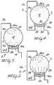
- the sterilization plant in accordance with the invention generally embodying a saturated-steam autoclave, is identified by reference numeral 1 .
- It comprises a boiler 2 externally having a boiler shell 3 and internally provided with a sterilization chamber 4 .
- a bottom area 3a is distinguisable in the boiler shell 3 and an upper area 4a is highlighted in the chamber 4.
- the boiler shell 3 has at least one opening and closing door and the chamber 4 is adapted to house trays in which the objects to be sterilized are arranged.
- the boiler 2 is provided with temperature and pressure control means consisting of sensors for example, such as a first thermal probe 5 located at the upper area 4a and capable of detecting the saturated steam temperature, and a second thermal probe 6 , disposed close to the bottom area 3a and capable of detecting the condensate temperature at the chamber 4 base.
- sensors for example, such as a first thermal probe 5 located at the upper area 4a and capable of detecting the saturated steam temperature, and a second thermal probe 6 , disposed close to the bottom area 3a and capable of detecting the condensate temperature at the chamber 4 base.
- thermal base probe 7 Disposed externally of chamber 4, and immediately below the bottom area 3a, there is a thermal base probe 7 , the function of which is that of controlling the heating members, as better clarified in the following.
- Safety devices are also provided, such as a safety valve 8 communicating via a pipeline 9 with a top hole 9a formed in the upper area of the boiler shell 3.
- control and safety devices known per se may be also provided, as well as members of the electronic type, known per se and not shown, for coordinating all the work steps.
- the plant 1 comprises several members for water, steam and air circulation at the boiler 2.
- Identified by 10 in Fig. 1 is a feed tank holding distilled water to be used for sterilization, and by 11 a discharge tank for collection of the water used for sterilization.
- the distilled water in the feed tank 10 is maintained between a minimum level and a maximum level, due to the presence of two level sensors 10a , whereas a maximum-level sensor alone 11a is provided in the discharge tank 11.
- the tanks are equipped with drain cocks 10b and 11b at the bottom.
- a feeding circuit 12 extends between the feed tank 10 and chamber 4 and it comprises members for water circulation such as a metering pump 13 capable of sending dosed amounts of water from the tank 10 to the chamber 4. Connected downstream of the metering pump 13 is a one-way valve 13a inhibiting return flows from the chamber 4 to the metering pump 13.
- the feeding circuit 12 opens, through an inlet 14a , into a heating block or unit 14 for heat formation, disposed in close contact with the boiler shell 3, as better clarified in the following.
- a discharge circuit 17 is connected to the chamber 4 bottom at a discharge opening 15 ; said discharge circuit is controlled by a solenoid exhaust valve 16 and extends until the discharge tank 11, where it comprises pumping members 18 and a branch 17a provided with an exhaust valve 17b .
- the discharge circuit 17 passes through the feed tank 10, upstream of the pumping members 18, where it is provided with a condenser coil 17c .
- bleeding members mainly comprising a bleeding circuit 19 one end of which terminates with a bleed hole 20 and an end portion 19a of which is connected both with the pumping members 18 and the exhaust valve 17b of the discharge circuit 17.
- the bleeding circuit 19 downstream of the bleed hole 20 comprises a solenoid bleed valve 21 enabling bleedings to be carried out upon command.
- a heat exchanger 22 is also provided downstream of the solenoid bleed valve 21, to condensate steam coming out of chamber 4.
- the plant 1 also comprises an air-admitting circuit 23 terminating at the pipeline 9 and provided with a second one-way valve 23a .
- the air-admitting circuit 23 preferably is comprised of a bacteriologic filter 24 for the external air and a compensation solenoid valve 25 controlling said air admission.
- the above mentioned heating block 14 intended for steam formation is disposed at the outside of chamber 4 but in close physical contact with the bottom area 3a of the boiler shell 3, so as to enable an efficient heat conduction between the heating block 14 and the boiler area where condensate is gathered.
- the heating block 14 is provided with the above mentioned inlet 14a and with an outlet 14b .
- a conveying circuit 26 preferably extending in contact with the external side of the boiler shell 3 and opening into the upper area 4a of chamber 4, through a steam-admitting hole 26a .
- the heating block 14 is adapted to convert to steam both the water from the circulation members 13 so as to form a first steam flow 27 conveyed into the conveying circuit 26, and the condensation water 28 gathered in the bottom area 3a of the boiler shell 3, to form a second steam flow 29 .
- the first steam flow 27 is substantially directed downwardly, whereas the second steam flow 29 is directed naturally upwardly.
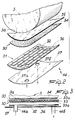
- the heating block 14 comprises substantially plate-like heating members 30 , the shape of which matches that of the bottom area 3a of the boiler shell 3 at least partly, and canalization members 31 .
- the heating members 30 are formed of a central layer 33 on which an electrical resistor 34 of 1500 watts is wound, and two outer layers 33a of electrically insulating material, enclosing the central layer 33 and the electrical resistor 34 between them.
- the canalization members 31 comprise a coil channel 32 brought into thermal conduction contact with the heating members 30.
- the coil channel 32 is formed in a plate 36 in contact with the heating members 30 and is embodied by a through slot provided in the plate 36 and closed by the heating members 30 at the upper part thereof and an outer band 37 at the lower part. Practically the coil channel 32 extends in the plate 36 thickness.
- the outer band 37 has an inlet hole 37a and an outlet hole 37b for the coil channel 32 which are to be aligned with the inlet 14a and outlet 14b.
- the coil channel 32 is defined by a plate 36 conveniently shaped and deformed so as to exhibit a coil hollow which is already closed at the lower part thereof.
- a sealing sheet made of stainless steel or another material adapted to be brought into contact with water and steam may be interposed between the heating members 30 and the coil channel 32.
- a conductive band 35 substantially extending around the whole boiler shell 3 and promoting distribution of heat from the heating members 30.
- This conductive band 35 is made of copper, aluminium or alloys thereof and transmits heat better than the walls of the boiler shell 3, generally made of stainless steel.
- the conductive band 35 leads to a more homogeneous heating of the whole boiler shell 3.
- the pumping members 18 After introducing the trays carrying the material to be sterilized into the chamber 4 and closing the chamber door, the pumping members 18 are turned on so that they suck the air contained in chamber 4 at least partly.
- the solenoid exhaust valve 16 enables suction of air through the discharge circuit 17.
- the solenoid bleed valve 21 is maintained open so that air can be sucked through the bleeding circuit 19 as well.
- the solenoid exhaust valve 16 closes communication with the discharge circuit 17.
- the solenoid bleed valve too closes and operation of the pumping members 18 is stopped.
- the metering pump 13 sends water in a dosed amount to the heating block, 14 which has been previously turned on so that the heating members 30 have already reached the foreseen operative temperature when water begins passing through the coil channel 32.
- the first steam flow condensate at least partly and the condensation water 28 thus formed is collected in the bottom area 3a of the boiler shell 3 (fig. 5).
- the heating block 14 however, intensely heats the boiler shell 3 as well, in that the heating members 30 are exactly in contact with the bottom area 3a of the boiler shell 3 and transfer heat thereto, so that evaporation of the condensation water 28 is caused and, as a result, a second steam flow directed upwardly is generated (Fig. 6).
- Heating of the boiler shell 3 and the flow rate of the first steam flow are adjusted depending both on the temperature and pressure values to be reached in chamber 4, and the thermal conditions of the heating block 14.
- the temperature and pressure values to be reached in chamber 4 typically are a pressure of at least approximately 205 kilopascals and a temperature of at least 134 degrees centigrade.
- thermal base probe 7 is intended for thermal control of the heating block 14 and that detections of said probe cause operation of the metering pump 13: in the presence of overheatings, the metering pump sends greater amounts of water that will give rise to an immediate cooling of the resistor 34.
- the compensation solenoid valve 25 is operated to enable admission of filtered air into the chamber 4, through the air-admitting circuit 23.
- the sterilization process performed by the plant in accordance with the invention takes place as follows, with reference to the steps of filling the chamber 4 with steam, carried out after suction of air from the chamber itself.
- First of all a heating step is executed, which consists in admitting a first steam flow formed by the heating members into the chamber 4, preferably at the upper area thereof.
- the first steam flow preferably impinges from top on the objects located inside the chamber 4.
- said first steam flow impinging on said objects partly condenses and is collected in a bottom area of the boiler shell 3, in the form of water.
- Said sanitization step initiates a true sterilization step, for example when in chamber 4 pressure and temperature values of 205 kilopascals and 134 degrees centigrade respectively are reached.
- the sterilization step lasts approximately four minutes.
- the fist steam flow itself carries out thermoregulation of said heat source: in the presence of overheatings the first steam flow is increased so as to achieve a greater heat absorption through the same. Therefore it does not appear necessary that operation of the heating members be stopped when said members tend to become overheated.
- the invention achieves important advantages.
- the plant has a single heating block the sizes of which are selected based on the heat amount usually required for causing the water built up within the boiler shell 3 to evaporate gradually, and in addition in many respects the plant remains similar to the autoclaves forming steam inside them.
- this single heating block 14 is not only capable of heating the boiler shell 3 so as to cause evaporation of the water in chamber 4, but also of admitting this water into chamber 4 in the form of a first steam flow, which flow combines with the second flow generated by normal heating of the boiler shell 3 so as to perform a sanitizing step.
- the sanitizing step on reaching appropriate pressure and temperature values, initiates a particularly efficient sterilization step, in that the presence of two steam flows of different directions leads to an inprovement in sterilization and a greater homogeneity in temperatures, since the material is better impinged on by steam.
Landscapes
- Health & Medical Sciences (AREA)
- Epidemiology (AREA)
- Life Sciences & Earth Sciences (AREA)
- Animal Behavior & Ethology (AREA)
- General Health & Medical Sciences (AREA)
- Public Health (AREA)
- Veterinary Medicine (AREA)
- Apparatus For Disinfection Or Sterilisation (AREA)
- Dental Tools And Instruments Or Auxiliary Dental Instruments (AREA)
Applications Claiming Priority (2)
| Application Number | Priority Date | Filing Date | Title |
|---|---|---|---|
| ITMI950852A IT1274396B (it) | 1995-04-28 | 1995-04-28 | Procedimento ed impianto di sterilizzazione a vapore in particolare per autoclavi |
| ITMI950852 | 1995-04-28 |
Publications (3)
| Publication Number | Publication Date |
|---|---|
| EP0742016A2 true EP0742016A2 (de) | 1996-11-13 |
| EP0742016A3 EP0742016A3 (de) | 1999-07-28 |
| EP0742016B1 EP0742016B1 (de) | 2002-07-17 |
Family
ID=11371466
Family Applications (1)
| Application Number | Title | Priority Date | Filing Date |
|---|---|---|---|
| EP96106007A Expired - Lifetime EP0742016B1 (de) | 1995-04-28 | 1996-04-17 | Anlage und Verfahren zum Sterilisieren mittels feuchter Hitze, insbesondere für Autoclaven zur Verwendung in der Zahnarztpraxis |
Country Status (5)
| Country | Link |
|---|---|
| US (1) | US5840248A (de) |
| EP (1) | EP0742016B1 (de) |
| DE (1) | DE69622316T2 (de) |
| ES (1) | ES2180670T3 (de) |
| IT (1) | IT1274396B (de) |
Cited By (7)
| Publication number | Priority date | Publication date | Assignee | Title |
|---|---|---|---|---|
| GB2333959A (en) * | 1998-02-05 | 1999-08-11 | Smiths Industries Plc | Autoclave |
| EP1462120A1 (de) * | 2003-03-24 | 2004-09-29 | M.O.COM. S.r.L. | Dampfbehälter für einen Dampfsterilisierapparat, insbesondere zum Sterilisieren von Zahnbehandlungsinstrumenten, und Verfahren zu dessen Herstellung |
| DE102004055150A1 (de) * | 2004-11-16 | 2006-05-24 | Human Nutrition Gmbh | Verfahren und Vorrichtung zur Reinigung von Überleitungssystemen für die enterale Ernährung |
| EP2181718A3 (de) * | 2008-09-30 | 2010-06-02 | Nybro s.r.o. | Autoklav |
| ITMI20130373A1 (it) * | 2013-03-12 | 2014-09-13 | Absolute Up S R L | Autoclave |
| CN105031677A (zh) * | 2015-07-02 | 2015-11-11 | 肖叶 | 一种空调管道内壁除菌器 |
| PL238866B1 (pl) * | 2019-05-27 | 2021-10-11 | Enbio Tech Spolka Z Ograniczona Odpowiedzialnoscia | Komora procesowa autoklawu parowego i sposób wytwarzania komory procesowej autoklawu parowego |
Families Citing this family (13)
| Publication number | Priority date | Publication date | Assignee | Title |
|---|---|---|---|---|
| NL1003576C1 (nl) * | 1996-07-12 | 1996-08-22 | Werkendam Installatiebedr Bv | Sterilisator. |
| US6001305A (en) * | 1998-05-12 | 1999-12-14 | Steris Corporation | Sterilizer with elliptical pressure vessel |
| US20060057021A1 (en) * | 2002-10-15 | 2006-03-16 | Sawyer Melvyn L | Fixed vacuum-insulated saturated steam autoclave |
| US8707861B2 (en) * | 2004-08-02 | 2014-04-29 | John Bean Technologies Corporation | Dry food pasteurization apparatus and method |
| ATE515274T1 (de) * | 2007-03-01 | 2011-07-15 | Getinge Sterilization Aktiebolag | Sterilisationsgerät, sterilisationsverfahren, verdampfungssystem und verwendung eines solchen verdampfungssystems |
| KR100862377B1 (ko) * | 2007-08-20 | 2008-10-13 | 대한민국(관리부서:농촌진흥청) | 진공상태를 이용한 직접 가열식 동물사체 처리장치 |
| IT1399017B1 (it) * | 2009-04-24 | 2013-04-05 | W & H Sterilization Srl | Disposizione per ottimizzare la distribuzione di temperatura all'interno di una camera di sterilizzazione ed autoclave ottenuta con tale dispositivo |
| US8808638B2 (en) * | 2011-09-16 | 2014-08-19 | Tomoda Selling & Sailing Co., Ltd. | Retort sterilization device, heating device, heat sterilization method, and heat treatment method |
| US10760853B1 (en) * | 2012-03-15 | 2020-09-01 | Crosstex International, Inc. | Automated thermal exchange system for autoclave sterilizer |
| EP2705779B1 (de) * | 2012-09-10 | 2014-09-03 | Electrolux Home Products Corporation N.V. | Dampferzeuger für ein Dampfgargerät |
| DK2745803T3 (en) * | 2012-12-20 | 2016-07-04 | W & H Dentalwerk Bürmoos GmbH | Processing chamber or treatment carrier and device for the treatment of at least one medical, in particular dental, instrument |
| EP3653288B1 (de) * | 2018-11-13 | 2022-06-29 | MELAG Medizintechnik GmbH & Co. KG | Dampfsterilisator und verfahren zu dessen betrieb |
| EP4541382A1 (de) | 2023-10-16 | 2025-04-23 | MELAG Medizintechnik GmbH & Co. KG | Verfahren zur dampfsterilisation in einem autoklav sowie autoklav |
Family Cites Families (9)
| Publication number | Priority date | Publication date | Assignee | Title |
|---|---|---|---|---|
| FR1370360A (fr) * | 1963-09-28 | 1964-08-21 | Flicoteaux Sa | Procédé de stérilisation par autoclave ainsi que les autoclaves pour la mise en oeuvre du procédé précédent ou procédé similaire |
| ZA715429B (en) * | 1970-09-10 | 1972-04-26 | Olivetti & Co Spa | A device for moulding parts to be sintered |
| DK163033C (da) * | 1987-10-02 | 1992-06-15 | Sven Karl Lennart Goof | Apparat til sterilisation af genstande isaer laege- og tandlaegeinstrumenter |
| JP2933330B2 (ja) * | 1989-10-30 | 1999-08-09 | 株式会社三浦研究所 | 蒸気滅菌器の内壁面構造 |
| US5271893A (en) * | 1989-11-24 | 1993-12-21 | Duncan Newman | Apparatus for steam sterilization of articles |
| US5196165A (en) * | 1990-12-20 | 1993-03-23 | The Pelton & Crane Company | Air bleeding apparatus for an autoclave |
| US5366693A (en) * | 1992-01-21 | 1994-11-22 | Mdt Corporation | Air/steam/liquid exhaust device for single cycle pressure vessel |
| DE4231204C1 (de) * | 1992-09-17 | 1994-04-14 | Stiefenhofer Gmbh C | Wasserdampferzeuger für einen Wasserdampfsterilisator |
| ATE190849T1 (de) * | 1993-11-19 | 2000-04-15 | M O Com S R L | Sterilisierungsverfahren und anlage für einen dampfautoklav |
-
1995
- 1995-04-28 IT ITMI950852A patent/IT1274396B/it active IP Right Grant
-
1996
- 1996-04-17 EP EP96106007A patent/EP0742016B1/de not_active Expired - Lifetime
- 1996-04-17 ES ES96106007T patent/ES2180670T3/es not_active Expired - Lifetime
- 1996-04-17 DE DE69622316T patent/DE69622316T2/de not_active Expired - Fee Related
- 1996-04-19 US US08/634,882 patent/US5840248A/en not_active Expired - Fee Related
Cited By (13)
| Publication number | Priority date | Publication date | Assignee | Title |
|---|---|---|---|---|
| GB2333959A (en) * | 1998-02-05 | 1999-08-11 | Smiths Industries Plc | Autoclave |
| EP1462120A1 (de) * | 2003-03-24 | 2004-09-29 | M.O.COM. S.r.L. | Dampfbehälter für einen Dampfsterilisierapparat, insbesondere zum Sterilisieren von Zahnbehandlungsinstrumenten, und Verfahren zu dessen Herstellung |
| DE102004055150A1 (de) * | 2004-11-16 | 2006-05-24 | Human Nutrition Gmbh | Verfahren und Vorrichtung zur Reinigung von Überleitungssystemen für die enterale Ernährung |
| DE102004055150B4 (de) * | 2004-11-16 | 2008-04-30 | Human Nutrition Gmbh | Vorrichtung zur Reinigung von Überleitungssystemen für die enterale Ernährung |
| EP2181718A3 (de) * | 2008-09-30 | 2010-06-02 | Nybro s.r.o. | Autoklav |
| WO2014141062A1 (en) * | 2013-03-12 | 2014-09-18 | Absolute Up S.R.L. | Autoclave |
| ITMI20130373A1 (it) * | 2013-03-12 | 2014-09-13 | Absolute Up S R L | Autoclave |
| CN105073145A (zh) * | 2013-03-12 | 2015-11-18 | 绝对向上有限责任公司 | 灭菌器 |
| JP2016510617A (ja) * | 2013-03-12 | 2016-04-11 | アブソリュート ユーピー エス.アール.エル. | オートクレーブ |
| CN105073145B (zh) * | 2013-03-12 | 2018-10-12 | 中西公司 | 灭菌器 |
| US10350316B2 (en) | 2013-03-12 | 2019-07-16 | Nakanishi Inc. | Autoclave |
| CN105031677A (zh) * | 2015-07-02 | 2015-11-11 | 肖叶 | 一种空调管道内壁除菌器 |
| PL238866B1 (pl) * | 2019-05-27 | 2021-10-11 | Enbio Tech Spolka Z Ograniczona Odpowiedzialnoscia | Komora procesowa autoklawu parowego i sposób wytwarzania komory procesowej autoklawu parowego |
Also Published As
| Publication number | Publication date |
|---|---|
| EP0742016A3 (de) | 1999-07-28 |
| ES2180670T3 (es) | 2003-02-16 |
| IT1274396B (it) | 1997-07-17 |
| ITMI950852A1 (it) | 1996-10-28 |
| ITMI950852A0 (it) | 1995-04-28 |
| DE69622316D1 (de) | 2002-08-22 |
| US5840248A (en) | 1998-11-24 |
| EP0742016B1 (de) | 2002-07-17 |
| DE69622316T2 (de) | 2003-03-13 |
Similar Documents
| Publication | Publication Date | Title |
|---|---|---|
| US5840248A (en) | Moist-heat sterilization apparatus and process, in particular to set up autoclaves for dental surgery use | |
| EP0992247B1 (de) | Autoklave | |
| US4263258A (en) | Steam-operated sterilization apparatus | |
| US5549038A (en) | Modulated steam cooker | |
| US7509034B2 (en) | Vapor production device and cooker with the same | |
| JP3796406B2 (ja) | エネルギー貯蔵兼エネルギー取り出し装置を備えた加熱調理装置 | |
| US4909988A (en) | Steam efficient prevacuum sterilizer cycle | |
| EP1795845A3 (de) | Dampfheizvorrichtung | |
| EP0654274B1 (de) | Sterilisierungsverfahren und Anlage für einen Dampfautoklav | |
| US6926874B2 (en) | Autoclave | |
| EP0937465B1 (de) | Verfahren und Gerät zur Dampfsterilisation, insbesondere für dentale Zwecke | |
| GB2044907A (en) | Heat pump, particularly vapour- compressing jet type heat pump | |
| WO2019085735A1 (zh) | 蒸汽巴氏灭菌设备 | |
| EP1424084A1 (de) | Vorrichtung und Verfahren zur Dampfsterilisation | |
| JPH0223306Y2 (de) | ||
| JP3785216B2 (ja) | 加熱冷却装置 | |
| RU2004116334A (ru) | Способ предварительной тепловой обработки зерен и оборудование для предварительной тепловой обработки зерен | |
| KR20170107234A (ko) | 과열증기를 이용한 건조 및 멸균 시스템 | |
| JP4409715B2 (ja) | 蒸気加熱装置 | |
| EP4199792B1 (de) | Steuerungsverfahren für einen ofen | |
| CN215982463U (zh) | 一种蒸汽灭菌器用蒸汽发生装置 | |
| KR200354398Y1 (ko) | 진공보일러형 두유액 가열장치 | |
| JP4087013B2 (ja) | 気化冷却装置 | |
| KR100471451B1 (ko) | 전기밥솥 및 그 제어방법 | |
| CN119014724A (zh) | 一种蒸汽烤箱 |
Legal Events
| Date | Code | Title | Description |
|---|---|---|---|
| PUAI | Public reference made under article 153(3) epc to a published international application that has entered the european phase |
Free format text: ORIGINAL CODE: 0009012 |
|
| AK | Designated contracting states |
Kind code of ref document: A2 Designated state(s): DE ES FR GB IT |
|
| PUAL | Search report despatched |
Free format text: ORIGINAL CODE: 0009013 |
|
| AK | Designated contracting states |
Kind code of ref document: A3 Designated state(s): DE ES FR GB IT |
|
| 17P | Request for examination filed |
Effective date: 19991206 |
|
| 17Q | First examination report despatched |
Effective date: 20000712 |
|
| GRAG | Despatch of communication of intention to grant |
Free format text: ORIGINAL CODE: EPIDOS AGRA |
|
| GRAG | Despatch of communication of intention to grant |
Free format text: ORIGINAL CODE: EPIDOS AGRA |
|
| GRAG | Despatch of communication of intention to grant |
Free format text: ORIGINAL CODE: EPIDOS AGRA |
|
| GRAH | Despatch of communication of intention to grant a patent |
Free format text: ORIGINAL CODE: EPIDOS IGRA |
|
| GRAH | Despatch of communication of intention to grant a patent |
Free format text: ORIGINAL CODE: EPIDOS IGRA |
|
| GRAA | (expected) grant |
Free format text: ORIGINAL CODE: 0009210 |
|
| AK | Designated contracting states |
Kind code of ref document: B1 Designated state(s): DE ES FR GB IT |
|
| REG | Reference to a national code |
Ref country code: GB Ref legal event code: FG4D |
|
| REF | Corresponds to: |
Ref document number: 69622316 Country of ref document: DE Date of ref document: 20020822 |
|
| ET | Fr: translation filed | ||
| REG | Reference to a national code |
Ref country code: ES Ref legal event code: FG2A Ref document number: 2180670 Country of ref document: ES Kind code of ref document: T3 |
|
| PLBE | No opposition filed within time limit |
Free format text: ORIGINAL CODE: 0009261 |
|
| STAA | Information on the status of an ep patent application or granted ep patent |
Free format text: STATUS: NO OPPOSITION FILED WITHIN TIME LIMIT |
|
| 26N | No opposition filed |
Effective date: 20030422 |
|
| PGFP | Annual fee paid to national office [announced via postgrant information from national office to epo] |
Ref country code: ES Payment date: 20080418 Year of fee payment: 13 Ref country code: DE Payment date: 20080530 Year of fee payment: 13 |
|
| PGFP | Annual fee paid to national office [announced via postgrant information from national office to epo] |
Ref country code: FR Payment date: 20080409 Year of fee payment: 13 |
|
| PGFP | Annual fee paid to national office [announced via postgrant information from national office to epo] |
Ref country code: GB Payment date: 20080404 Year of fee payment: 13 |
|
| GBPC | Gb: european patent ceased through non-payment of renewal fee |
Effective date: 20090417 |
|
| REG | Reference to a national code |
Ref country code: FR Ref legal event code: ST Effective date: 20091231 |
|
| PG25 | Lapsed in a contracting state [announced via postgrant information from national office to epo] |
Ref country code: DE Free format text: LAPSE BECAUSE OF NON-PAYMENT OF DUE FEES Effective date: 20091103 |
|
| PG25 | Lapsed in a contracting state [announced via postgrant information from national office to epo] |
Ref country code: GB Free format text: LAPSE BECAUSE OF NON-PAYMENT OF DUE FEES Effective date: 20090417 Ref country code: FR Free format text: LAPSE BECAUSE OF NON-PAYMENT OF DUE FEES Effective date: 20091222 |
|
| REG | Reference to a national code |
Ref country code: ES Ref legal event code: FD2A Effective date: 20090418 |
|
| PG25 | Lapsed in a contracting state [announced via postgrant information from national office to epo] |
Ref country code: ES Free format text: LAPSE BECAUSE OF NON-PAYMENT OF DUE FEES Effective date: 20090418 |
|
| PGFP | Annual fee paid to national office [announced via postgrant information from national office to epo] |
Ref country code: IT Payment date: 20150325 Year of fee payment: 20 |