EP0740717B1 - High strength core for wire ropes - Google Patents
High strength core for wire ropes Download PDFInfo
- Publication number
- EP0740717B1 EP0740717B1 EP94922963A EP94922963A EP0740717B1 EP 0740717 B1 EP0740717 B1 EP 0740717B1 EP 94922963 A EP94922963 A EP 94922963A EP 94922963 A EP94922963 A EP 94922963A EP 0740717 B1 EP0740717 B1 EP 0740717B1
- Authority
- EP
- European Patent Office
- Prior art keywords
- core
- rod
- bundle
- polymeric material
- axis
- Prior art date
- Legal status (The legal status is an assumption and is not a legal conclusion. Google has not performed a legal analysis and makes no representation as to the accuracy of the status listed.)
- Expired - Lifetime
Links
Images


Classifications
-
- D—TEXTILES; PAPER
- D07—ROPES; CABLES OTHER THAN ELECTRIC
- D07B—ROPES OR CABLES IN GENERAL
- D07B1/00—Constructional features of ropes or cables
- D07B1/06—Ropes or cables built-up from metal wires, e.g. of section wires around a hemp core
- D07B1/0673—Ropes or cables built-up from metal wires, e.g. of section wires around a hemp core having a rope configuration
- D07B1/0686—Ropes or cables built-up from metal wires, e.g. of section wires around a hemp core having a rope configuration characterised by the core design
-
- D—TEXTILES; PAPER
- D07—ROPES; CABLES OTHER THAN ELECTRIC
- D07B—ROPES OR CABLES IN GENERAL
- D07B2201/00—Ropes or cables
- D07B2201/10—Rope or cable structures
- D07B2201/1012—Rope or cable structures characterised by their internal structure
- D07B2201/102—Rope or cable structures characterised by their internal structure including a core
-
- D—TEXTILES; PAPER
- D07—ROPES; CABLES OTHER THAN ELECTRIC
- D07B—ROPES OR CABLES IN GENERAL
- D07B2201/00—Ropes or cables
- D07B2201/10—Rope or cable structures
- D07B2201/1028—Rope or cable structures characterised by the number of strands
- D07B2201/1032—Rope or cable structures characterised by the number of strands three to eight strands respectively forming a single layer
-
- D—TEXTILES; PAPER
- D07—ROPES; CABLES OTHER THAN ELECTRIC
- D07B—ROPES OR CABLES IN GENERAL
- D07B2201/00—Ropes or cables
- D07B2201/10—Rope or cable structures
- D07B2201/104—Rope or cable structures twisted
-
- D—TEXTILES; PAPER
- D07—ROPES; CABLES OTHER THAN ELECTRIC
- D07B—ROPES OR CABLES IN GENERAL
- D07B2201/00—Ropes or cables
- D07B2201/20—Rope or cable components
- D07B2201/2015—Strands
- D07B2201/2023—Strands with core
-
- D—TEXTILES; PAPER
- D07—ROPES; CABLES OTHER THAN ELECTRIC
- D07B—ROPES OR CABLES IN GENERAL
- D07B2201/00—Ropes or cables
- D07B2201/20—Rope or cable components
- D07B2201/2015—Strands
- D07B2201/2036—Strands characterised by the use of different wires or filaments
- D07B2201/2037—Strands characterised by the use of different wires or filaments regarding the dimension of the wires or filaments
-
- D—TEXTILES; PAPER
- D07—ROPES; CABLES OTHER THAN ELECTRIC
- D07B—ROPES OR CABLES IN GENERAL
- D07B2201/00—Ropes or cables
- D07B2201/20—Rope or cable components
- D07B2201/2015—Strands
- D07B2201/2038—Strands characterised by the number of wires or filaments
- D07B2201/204—Strands characterised by the number of wires or filaments nine or more wires or filaments respectively forming multiple layers
-
- D—TEXTILES; PAPER
- D07—ROPES; CABLES OTHER THAN ELECTRIC
- D07B—ROPES OR CABLES IN GENERAL
- D07B2201/00—Ropes or cables
- D07B2201/20—Rope or cable components
- D07B2201/2047—Cores
- D07B2201/2048—Cores characterised by their cross-sectional shape
-
- D—TEXTILES; PAPER
- D07—ROPES; CABLES OTHER THAN ELECTRIC
- D07B—ROPES OR CABLES IN GENERAL
- D07B2201/00—Ropes or cables
- D07B2201/20—Rope or cable components
- D07B2201/2047—Cores
- D07B2201/2048—Cores characterised by their cross-sectional shape
- D07B2201/2049—Cores characterised by their cross-sectional shape having protrusions extending radially functioning as spacer between strands or wires
-
- D—TEXTILES; PAPER
- D07—ROPES; CABLES OTHER THAN ELECTRIC
- D07B—ROPES OR CABLES IN GENERAL
- D07B2201/00—Ropes or cables
- D07B2201/20—Rope or cable components
- D07B2201/2047—Cores
- D07B2201/2052—Cores characterised by their structure
- D07B2201/2053—Cores characterised by their structure being homogeneous
-
- D—TEXTILES; PAPER
- D07—ROPES; CABLES OTHER THAN ELECTRIC
- D07B—ROPES OR CABLES IN GENERAL
- D07B2201/00—Ropes or cables
- D07B2201/20—Rope or cable components
- D07B2201/2047—Cores
- D07B2201/2066—Cores characterised by the materials used
-
- D—TEXTILES; PAPER
- D07—ROPES; CABLES OTHER THAN ELECTRIC
- D07B—ROPES OR CABLES IN GENERAL
- D07B2201/00—Ropes or cables
- D07B2201/20—Rope or cable components
- D07B2201/2047—Cores
- D07B2201/2067—Cores characterised by the elongation or tension behaviour
- D07B2201/2068—Cores characterised by the elongation or tension behaviour having a load bearing function
-
- D—TEXTILES; PAPER
- D07—ROPES; CABLES OTHER THAN ELECTRIC
- D07B—ROPES OR CABLES IN GENERAL
- D07B2205/00—Rope or cable materials
- D07B2205/20—Organic high polymers
- D07B2205/201—Polyolefins
Definitions
- This invention relates to solid polymeric cores for wire ropes.
- GB-A-1 092 321 discloses a core which consists of polyamide, polyester, or polypropylene monofilaments helically twisted together and which has been compacted under tension at a temperature above the softening point of the monofilaments.
- GB-A-2 219 014 discloses a core in accordance with the pre-characterising part of claim 1.
- the document also discloses a wire rope in accordance with the pre-characterising part of claim 16.
- GB-A-1 092 321 discloses a method of producing a compacted core made of plastic monofilaments which are capable of molecular re-orientation when heated and stressed, in which the formed core (made up of monofilaments helically twisted together) is subjected to axial tension, radial compression, and heat, whereby to compact the monofilaments and deform their cross-sections into closely interfitting shapes forming a symmetrical geometric pattern.
- the core is not formed with grooves.
- the present invention provides a solid polymeric core for wire rope, the core having a plurality of concave grooves, each extending continuously in a direction along the core, the grooves being equally spaced around the axis of the core, characterised in that the core consists of a body of polymeric material formed by simultaneous elongation and cross-sectional deformation in the solid state, the polymeric material having a structure orientated substantially in the axial direction of the core, and the grooves being parallel to the axis.
- the core is preferably of unitary or one-piece construction, but alternative constructions comprising a plurality of elements are possible.
- the solid elongate body may be of coaxial construction, being formed from successive layers of polymeric material (which may differ from layer to layer).
- the body may be an assembly of mutually parallel polymeric elements.
- the invention also provides a method of producing the said core in a single- or multi-stage operation using a controlled means of forming the core whilst in its solid state.
- the invention further provides wire rope containing a solid polymeric core of unitary or multi-element construction in which the structure of the core material is preferentially orientated in a substantially axial direction.
- the core is externally profiled to correspond with the internal geometry of the rope.
- the wire rope may, for example, comprise 6 or 8 outer strands over the said core.
- the core may contribute significantly (e.g. 5%, up to 10%, or more) to the load bearing capability of the rope.
- the preferred method comprises extruding a nominally cylindrical rod (or a bundle of rods) of polymeric material with a substantially greater cross-sectional area than that required in the finished core, and then applying a forming operation to the rod (or bundle) in the solid state.
- This forming operation is designed and controlled to both elongate the rod (or rods) in the axial sense and to reform the cross-sectional shape of the rod (or bundle) to closely match the requirements of the end product.
- the process of elongating the polymeric material in its solid state substantially enhances its mechanical properties.
- the Tensile Strength of the elongated core may be increased for example by a factor of 10 and the elastic modulus may be increased by a factor of as much as 20 by comparison with the as-extruded rod.
- the reason for this is that the forming operation induces reorientation of the crystalline structure of the material, whereby the crystals are drawn out and elongated in the axial direction.
- the process of reforming the cross-sectional profile has two beneficial effects. Firstly, it enables the size of the core to be closely toleranced to suit the desired rope diameter, improving both the longitudinal consistency and the concentricity of the core relative to the original extruded rod shape, which has a tendency to become oval on solidifying (unless extruded vertically). Secondly, it allows the shape of the core to be modified to closely conform to the desired internal profile of the wire rope.
- the core may be polygonal in cross-section, where the number of faces is chosen to match the number of strands in the rope, and the faces will be concave with a radius of curvature similar or equivalent to the strand radius.
- the forming process draws out and elongates the crystals of the orientatable polymers in the axial direction, which enhances the axial properties of the core, in that the crystals become somewhat whisker-like and stronger (through strain-hardening mechanisms).
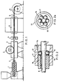
- Figure 1 shows a horizontal screw extruder 1 producing a rod 7 (or a round bundle of rods).
- the elongation process is preferably carried out in-line with the extruder, so that the rod (or bundle) may be operated upon in its solid state but before it has had chance to cool below an optimum working temperature. This avoids the problems associated with re-heating the material up to a suitable temperature, which may be an expensive and rate-controlling operation.
- the elongation process may be carried out between two traction devices which are geared to one another, e.g. by mechanical or electronic means, to maintain a pre-determined ratio of linear speed. For example, if it is desired to elongate the rod (or bundle) by 100%, then the second traction device will be set to operate at twice the linear speed of the first traction device.
- the first traction device may be a capstan 2 of single-drum or double-drum construction, or a "caterpillar” drive (comprising two endless friction belts), being suitable both for gripping the round rod 7 (or bundle) and for immersion in a fluid bath 3, if required for temperature control purposes.
- the second traction device may be either a capstan or a "caterpillar” drive 5 (comprising two endless friction belts) having regard to the shape and damage resistance of the elongated core 8 being produced.
- the core 8 is finally wound on a take-up reel 6.
- Control of the elongation process may be enhanced by applying radial pressure over a section of the rod (or bundle) between the two traction devices, as shown schematically in Figure 1.
- the pressure generating device may be a tubular die 4 (similar to a wire drawing die) or a system of shaped rollers. Because of the difficulties of providing an adjustable die or roller system, a preferred set-up procedure may be to:-
- the extruder drive means will also preferably be linked automatically to at least one of the traction devices 2,5 in terms of relative throughput, so that the line speed may be varied without substantially changing the relative process conditions.
- Control of the rod temperature during the elongation stage may be critical to the process and can best be effected by positioning a hot-water (or fluid) bath (e.g. at about 90°C) between the extruder and the die (or pressure generating device).
- a hot-water (or fluid) bath e.g. at about 90°C
- a possible arrangement of the equipment is to mount the die on the end of the water (or fluid) bath.
- a second bath or trough (not shown) containing water (or fluid) at a lower temperature may be located after the die to assist in the cooling of the core before it encounters the second traction device.
- Means for reforming the shape of the core may comprise a contoured die, a set of shaped rollers, or preferably the spherical ball forming device which is disclosed below. This has the unique advantage of being easily assembled and adjusted onto the rod (or bundle) without interrupting the process. In practice it is expected that the reforming operation will be carried out in conjunction with the elongation operation and preferably in line with the extruder.
- the forming device described below may therefore also constitute the means of applying radial pressure referred to above in the elongation operation. It will be recognised that extrusion is a continuous process and that in order to carry out reforming operations downstream and in-line with the extruder, it is preferable for the forming equipment to be both demountable and adjustable. These features are provided by the equipment described below.
- Figure 2 depicts the basic principle of a spherical ball device in which balls 12 are free to rotate within a housing 11 having a frustoconical bore 14, the taper of which provides the means of adjusting their spacial geometry with regard to the plastics rod 7 (or bundle of rods) which it is desired to modify the shape of and which passes through the centre of the device.
- the radial positioning of the ball 12 may be controlled by means of a thrust ring or washer 13 arranged normal to the axis of the conical bore 14 and provided with fine adjustment in the axial direction, e.g. by means of a carrier 16 screwed into the housing 11.
- the number of balls 12 will be chosen to match the number of strands in the rope for which the core 8 is intended, and the size of the balls will be selected to give the desired profile in the finished core 8. In the limit of the core adjustment means, the balls 12 will all just touch one another and the thrust ring 13, so that their uniform positioning around the conical bore 14 is ensured.
- the frustoconical bore 14 is provided with axially aligned or helical grooves into which the balls 12 are located.
- the bore grooves are preferably spaced equidistant around the conical bore so that uniform spacing of the balls is maintained even when they are not touching on another. This allows a core to be produced with a wider separation of its grooves and hence provides a rope with a more generous spacing of the strands.
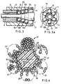
- the forming device comprises a series of annular rings of spherical balls 12a, 12b, 12c at reducing radial distances from the axis of the conical bore 14, to provide a progressive transformation of the rod shape, as illustrated in Figure 3.
- the size of the successive balls 12,b,c may also reduce progressively and each annular ring of balls may be separately adjustable.
- the balls are located in axially aligned equi-spaced grooves 17.
- the outer casing 11 may be rotatably mounted.
- a core having a helically grooved profile may then be produced either by providing a drive means to rotate the forming device in a geared relationship to the speed of the (final) traction means, or by arranging the successive rings of balls in a helical array, and allowing the forming means to rotate naturally, i.e. of its own accord.
- a given size of device i.e. casing 11, may be utilised to produce a range of core sizes.
- the number of balls (and hence grooves in the tapered bore, if present) will be determined by the rope construction.
- Coarse adjustment of core size/profile is provided by selecting an appropriate spherical ball size (or sizes) and fine adjustment is provided by means of the axial positioning of the thrust ring 13.
- the spherical balls 12 (12a-c) will preferably be of hardened steel or other wear resistant material such as tungsten carbide, and casing 11 of hardened steel or hard bronze.
- the thrust ring 13 may also be a hard bronze, to minimise wear and the need for lubricant.
- the surface finish of the spherical balls may be advantageously controlled to encourage their rotation with the polymer (core) surface.
- the angle of taper of the conical bore 14 may be advantageously selected to ensure that the balls are drawn into the housing 11 and retained there by the resultant of the shear and radial forces which act upon them without the need for a rear retaining ring or collar.
- each ball (or each alternate ball) will naturally run along the valley defined between two adjacent rods, thereby automatically resulting in a cross-sectional profile of rotationally symmetrical shape.
- a multi-stage process may be required, involving a series of traction devices with forming devices between each neighbouring part and with the necessary inter-heating or inter-cooling means to maintain the polymer temperature at an optimum level for each reduction/shaping stage, having regard to achieving economic operating speeds, e.g. greater than 10 m/min, preferably greater than 20 m/min, more preferably greater than 30 m/min.
- the final shaping and/or twisting operation on the core may be carried out on the rope closing machine, where the forming device is preferably located close to the forming point of the machine so that final adjustments can be made to the core size immediately adjacent to its introduction to the rope and can provide the ultimate control of the rope manufacturing process with respect to product size.
- Figure 4 shows a rope comprising six strands 21 wound on a core 8 having six concave surfaces 22 and containing generally whisker-like crystals orientated in the axial direction and also generally ribbon-like crystals orientated in the axial direction and in the radial directions 23 indicated.
- Figure 5a shows a bundle 31 of three round rods 32 which is processed by the above-described apparatus to produce the three-piece core 33 shown in Figure 5b for a 6-strand rope.
- the core 33 has six concave surfaces 34 and contains generally whisker-like crystals orientated in the axial direction and also generally ribbon-like crystals orientated in the axial direction and in radial directions towards the protuberances 36 between the concave surfaces 34.
- Figure 6a shows a bundle 31' of four round rods 32 which is processed as described above to produce the four-piece core 33' shown in Figure 6b for an 8-strand rope.
- Figure 7a shows a two-piece rod 40 produced by extruding a cylindrical element 41 of orientatable polymeric material and then extruding onto it an outer layer 42 of orientatable polymeric material.
- the two materials may be the same or different.
- the rod 40 is processed in the same way as the rod 7 described above to produce the core 43 shown in Figure 7b for a 6-strand rope.
- Both the central part 44 and the outer part 46 of the core 43 comprise generally whisker-like crystals orientated in the axial direction.
- the outer part includes generally ribbon-like crystals orientated in the axial direction and in radial directions towards protuberances 47 between concave surface 48 for receiving the strands of the rope.
- FIG 8a shows a bundle 51 of seven round rods 52 which is processed as described above to produce the seven-piece core 53 shown in Figure 8b for a 6-strand rope.
- each outer element 54 of the core 53 includes generally ribbon-like crystals orientated in the axial direction and in the radial direction towards a protuberance 56.
- the polymeric material of the central element 57 may be different from that of the outer elements.
- thermoplastic materials which are amenable to solid state forming and preferably show a pronounced increase in mechanical properties by strain hardening, i.e. equivalent to cold-working in metals.
- strain hardening i.e. equivalent to cold-working in metals.
- the polyolefins respond favourably to such treatment, and High Density Polyethylene and Polyethylene Copolymers and Polypropylene have been shown to be suitable candidate materials.
- new and improved blends of material are constantly being produced, including (fibre) reinforced polymers, and this invention may be applied to many of them with equal benefit.
- the cores illustrated in the drawings have been described as applied to rope constructions of single-layer type, but the cores may be used equally effectively in multi-strand ropes, i.e. ropes which comprise more than one layer of strands.
Landscapes
- Ropes Or Cables (AREA)
- Extrusion Moulding Of Plastics Or The Like (AREA)
- Shaping By String And By Release Of Stress In Plastics And The Like (AREA)
- Organic Insulating Materials (AREA)
- Communication Cables (AREA)
- Addition Polymer Or Copolymer, Post-Treatments, Or Chemical Modifications (AREA)
- Optical Integrated Circuits (AREA)
Applications Claiming Priority (3)
| Application Number | Priority Date | Filing Date | Title |
|---|---|---|---|
| GB9316190 | 1993-08-04 | ||
| GB9316190A GB2280686B (en) | 1993-08-04 | 1993-08-04 | Orientated polymeric core for wire ropes |
| PCT/GB1994/001672 WO1995004855A1 (en) | 1993-08-04 | 1994-08-01 | High strength core for wire ropes |
Publications (2)
| Publication Number | Publication Date |
|---|---|
| EP0740717A1 EP0740717A1 (en) | 1996-11-06 |
| EP0740717B1 true EP0740717B1 (en) | 2000-05-10 |
Family
ID=10739977
Family Applications (1)
| Application Number | Title | Priority Date | Filing Date |
|---|---|---|---|
| EP94922963A Expired - Lifetime EP0740717B1 (en) | 1993-08-04 | 1994-08-01 | High strength core for wire ropes |
Country Status (16)
| Country | Link |
|---|---|
| US (1) | US5797254A (it) |
| EP (1) | EP0740717B1 (it) |
| JP (1) | JPH09501207A (it) |
| KR (1) | KR100302689B1 (it) |
| CN (1) | CN1130929A (it) |
| AT (1) | ATE192797T1 (it) |
| AU (1) | AU682886B2 (it) |
| BR (1) | BR9407173A (it) |
| CA (1) | CA2168779C (it) |
| DE (1) | DE69424444T2 (it) |
| GB (1) | GB2280686B (it) |
| IN (1) | IN184545B (it) |
| NO (1) | NO960446L (it) |
| SG (1) | SG46538A1 (it) |
| WO (1) | WO1995004855A1 (it) |
| ZA (1) | ZA945794B (it) |
Families Citing this family (26)
| Publication number | Priority date | Publication date | Assignee | Title |
|---|---|---|---|---|
| GB2332454B (en) * | 1997-12-19 | 2000-02-16 | Bridon Plc | Rope for conveying systems |
| FR2783585B1 (fr) * | 1998-09-23 | 2000-11-17 | Trefileurope | Cable mixte a ame synthetique pour le levage ou de traction |
| CA2262307C (en) | 1999-02-23 | 2006-01-24 | Joseph Misrachi | Low stretch elevator rope |
| FR2824849B1 (fr) * | 2001-05-17 | 2005-06-10 | Trefileurope | Cable dynamique a proprietes ameliorees, et procede et installation de fabrication d'un tel cable |
| JP3756878B2 (ja) * | 2002-12-18 | 2006-03-15 | 東京製綱株式会社 | 被覆ワイヤロープ |
| JP4912931B2 (ja) * | 2007-03-22 | 2012-04-11 | 住友化学株式会社 | 熱電変換モジュールの製造方法及び熱電変換モジュール |
| US20100072660A1 (en) * | 2007-03-27 | 2010-03-25 | Felix Achille | Low relative crystallinity die drawing process for a cavitated filled oriented polymer composition |
| FR2915620B1 (fr) * | 2007-04-27 | 2011-02-11 | Nexans | Cable de controle electrique |
| ITMI20072281A1 (it) * | 2007-12-05 | 2009-06-06 | Redaelli Tecna S P A Div Teci | Fune metallica a caratteristiche migliorate |
| WO2009079206A1 (en) * | 2007-12-17 | 2009-06-25 | Dow Global Technologies Inc. | Shaping die and its use in a solid state drawing process |
| RU2553967C2 (ru) | 2011-04-14 | 2015-06-20 | Отис Элевэйтор Компани | Канат или ремень с покрытием для подъемных систем |
| FR2986245B1 (fr) * | 2012-01-27 | 2015-06-19 | Cousin Trestec | Cable et procede de fabrication dudit cable. |
| EP2841642B1 (en) * | 2012-04-24 | 2016-07-27 | NV Bekaert SA | Hybirid rope or hybrid strand |
| JP5806644B2 (ja) * | 2012-05-31 | 2015-11-10 | 東京製綱株式会社 | ハイブリッド心ロープ |
| EP2971331B1 (en) * | 2013-03-14 | 2018-09-12 | WireCo WorldGroup Inc. | Torque balanced hybrid rope |
| CH708244B1 (de) * | 2013-06-28 | 2016-10-14 | Fatzer Ag | Drahtseil sowie ein Verfahren zu dessen Herstellung. |
| CN105297503A (zh) * | 2015-11-19 | 2016-02-03 | 鞍钢钢绳有限责任公司 | 一种钢丝绳用预成形绳芯及其制作方法 |
| CN109689967A (zh) * | 2016-09-13 | 2019-04-26 | 东京制纲株式会社 | 动索用钢丝绳及其制造方法 |
| US11155352B2 (en) * | 2017-08-22 | 2021-10-26 | Breeze-Eastern Llc | Aircraft mounted hoist system having a multi-stranded wire rope cable |
| CA3088472A1 (en) | 2018-03-06 | 2019-09-12 | Bridon International Limited | Synthetic rope |
| WO2019185487A1 (en) * | 2018-03-26 | 2019-10-03 | Bridon International Limited | Synthetic fiber rope |
| JP7730621B2 (ja) * | 2019-11-12 | 2025-08-28 | 東京製綱株式会社 | ワイヤロープの伸び特性の制御方法 |
| DE112020007718T5 (de) * | 2020-10-20 | 2023-08-10 | Mitsubishi Electric Corporation | Hochfeste Faseranordnung, Seil und Seilstruktur |
| CN115325103B (zh) * | 2022-08-11 | 2025-08-15 | 巨力索具股份有限公司 | 一种万向可拆卸绳芯 |
| CN115852721A (zh) * | 2022-11-30 | 2023-03-28 | 江苏亚盛金属制品有限公司 | 高韧性钢丝绳 |
| CN116536818B (zh) * | 2023-05-23 | 2024-09-24 | 江苏兴达钢帘线股份有限公司 | 一种层状结构钢帘线的生产方法 |
Family Cites Families (7)
| Publication number | Priority date | Publication date | Assignee | Title |
|---|---|---|---|---|
| US1183487A (en) * | 1915-04-16 | 1916-05-16 | Thomas Gore | Wire strand or rope. |
| US2136866A (en) * | 1938-06-10 | 1938-11-15 | Malcolm W Reed | Wire rope |
| GB1092321A (en) * | 1963-07-30 | 1967-11-22 | British Ropes Ltd | Improvements in or relating to strands, ropes or cores of plastic monofilaments |
| US4348350A (en) * | 1980-09-26 | 1982-09-07 | Michigan Molecular Institute | Ultra-drawing crystalline polymers under high pressure |
| US4950151A (en) * | 1985-01-31 | 1990-08-21 | Zachariades Anagnostic E | Rolling die for producing high modulus products |
| GB2219014B (en) * | 1988-05-19 | 1991-12-18 | Bridon Plc | Cores for wire ropes |
| CA2041206C (en) * | 1991-04-25 | 1996-11-19 | Joe Misrachi | Wire rope having a plastic jacketed core with wormings |
-
1993
- 1993-08-04 GB GB9316190A patent/GB2280686B/en not_active Expired - Fee Related
-
1994
- 1994-08-01 WO PCT/GB1994/001672 patent/WO1995004855A1/en not_active Ceased
- 1994-08-01 KR KR1019960700489A patent/KR100302689B1/ko not_active Expired - Fee Related
- 1994-08-01 JP JP7506279A patent/JPH09501207A/ja active Pending
- 1994-08-01 SG SG1996005723A patent/SG46538A1/en unknown
- 1994-08-01 US US08/591,448 patent/US5797254A/en not_active Expired - Lifetime
- 1994-08-01 DE DE69424444T patent/DE69424444T2/de not_active Expired - Fee Related
- 1994-08-01 EP EP94922963A patent/EP0740717B1/en not_active Expired - Lifetime
- 1994-08-01 CA CA002168779A patent/CA2168779C/en not_active Expired - Fee Related
- 1994-08-01 AT AT94922963T patent/ATE192797T1/de not_active IP Right Cessation
- 1994-08-01 BR BR9407173A patent/BR9407173A/pt not_active Application Discontinuation
- 1994-08-01 AU AU72688/94A patent/AU682886B2/en not_active Ceased
- 1994-08-01 CN CN94193397A patent/CN1130929A/zh active Pending
- 1994-08-03 IN IN730MA1994 patent/IN184545B/en unknown
- 1994-08-03 ZA ZA945794A patent/ZA945794B/xx unknown
-
1996
- 1996-02-02 NO NO960446A patent/NO960446L/no unknown
Also Published As
| Publication number | Publication date |
|---|---|
| DE69424444D1 (de) | 2000-06-15 |
| US5797254A (en) | 1998-08-25 |
| GB2280686A (en) | 1995-02-08 |
| DE69424444T2 (de) | 2000-12-21 |
| HK1014200A1 (en) | 1999-09-24 |
| SG46538A1 (en) | 1998-02-20 |
| GB9316190D0 (en) | 1993-09-22 |
| KR100302689B1 (ko) | 2001-12-15 |
| EP0740717A1 (en) | 1996-11-06 |
| NO960446D0 (no) | 1996-02-02 |
| AU682886B2 (en) | 1997-10-23 |
| CA2168779A1 (en) | 1995-02-16 |
| NO960446L (no) | 1996-03-22 |
| IN184545B (it) | 2000-09-02 |
| ZA945794B (en) | 1995-03-09 |
| CN1130929A (zh) | 1996-09-11 |
| ATE192797T1 (de) | 2000-05-15 |
| GB2280686B (en) | 1997-05-07 |
| WO1995004855A1 (en) | 1995-02-16 |
| BR9407173A (pt) | 1996-09-17 |
| JPH09501207A (ja) | 1997-02-04 |
| AU7268894A (en) | 1995-02-28 |
| CA2168779C (en) | 2004-02-24 |
Similar Documents
| Publication | Publication Date | Title |
|---|---|---|
| EP0740717B1 (en) | High strength core for wire ropes | |
| JP2583449B2 (ja) | 管状製品、殊にカテーテルを製造する方法 | |
| EP2165017B1 (de) | Seil, kombiniertes seil aus kunststofffasern und stahldrahtlitzen sowie kombinierte litze aus kunststofffasern und stahldrähten | |
| EP1103653A1 (de) | Verfahren und Verseilvorrichtung zur Herstellung eines Seiles oder Seilelements | |
| JPH0921084A (ja) | ワイヤロープ構造 | |
| US4641492A (en) | Rope-twisting machine for making ropes | |
| KR100250193B1 (ko) | 권선 로우프용 코아 | |
| EP0414786B2 (en) | Cores for wire ropes | |
| EP2470339B1 (de) | Langfaserverstärktes polymermaterial und verfahren und anlage zu dessen herstellung | |
| HK1014200B (en) | High strength core for wire ropes | |
| US4210012A (en) | Roll compacting of stranded conductor | |
| EP1194620B1 (de) | Verfahren zur herstellung von borsten | |
| JP3538649B2 (ja) | カーボン繊維ストランド及びその製造方法 | |
| DE3904588C2 (it) | ||
| US5375404A (en) | Wide rope with reduced internal contact stresses | |
| GB2320933A (en) | Manufacture of wire rope | |
| WO1989000493A1 (en) | Oriented polymer articles | |
| DE102011002182B4 (de) | Flexible Litze sowie Verfahren zum Herstellen einer flexiblen Litze | |
| AT335863B (de) | Verfahren zur herstellung eines verstarkten gewebes, insbesondere als verstarkungseinlage fur luftreifen | |
| US7786387B2 (en) | Composite electrical conductor and method for producing it | |
| EP2858800B1 (de) | Einzugswalze für stranggranulatoren sowie verfahren zur herstellung einer solchen | |
| AT395732B (de) | Metallkord zur verstaerkung von elastomerkoerper | |
| JPH09273089A (ja) | ゴム補強用スチールコード及びゴム複合体 | |
| RU2092259C1 (ru) | Матрица для прессования изделий (варианты) | |
| AT322997B (de) | Verstärktes gewebe |
Legal Events
| Date | Code | Title | Description |
|---|---|---|---|
| PUAI | Public reference made under article 153(3) epc to a published international application that has entered the european phase |
Free format text: ORIGINAL CODE: 0009012 |
|
| 17P | Request for examination filed |
Effective date: 19960129 |
|
| AK | Designated contracting states |
Kind code of ref document: A1 Designated state(s): AT BE CH DE FR GB IT LI LU NL SE |
|
| TPAD | Observations filed by third parties |
Free format text: ORIGINAL CODE: EPIDOS TIPA |
|
| 17Q | First examination report despatched |
Effective date: 19971014 |
|
| GRAG | Despatch of communication of intention to grant |
Free format text: ORIGINAL CODE: EPIDOS AGRA |
|
| GRAG | Despatch of communication of intention to grant |
Free format text: ORIGINAL CODE: EPIDOS AGRA |
|
| GRAH | Despatch of communication of intention to grant a patent |
Free format text: ORIGINAL CODE: EPIDOS IGRA |
|
| GRAH | Despatch of communication of intention to grant a patent |
Free format text: ORIGINAL CODE: EPIDOS IGRA |
|
| GRAA | (expected) grant |
Free format text: ORIGINAL CODE: 0009210 |
|
| AK | Designated contracting states |
Kind code of ref document: B1 Designated state(s): AT BE CH DE FR GB IT LI LU NL SE |
|
| REF | Corresponds to: |
Ref document number: 192797 Country of ref document: AT Date of ref document: 20000515 Kind code of ref document: T |
|
| REG | Reference to a national code |
Ref country code: CH Ref legal event code: EP |
|
| REF | Corresponds to: |
Ref document number: 69424444 Country of ref document: DE Date of ref document: 20000615 |
|
| REG | Reference to a national code |
Ref country code: CH Ref legal event code: NV Representative=s name: RITSCHER & SEIFERT |
|
| ITF | It: translation for a ep patent filed | ||
| ET | Fr: translation filed | ||
| PLBE | No opposition filed within time limit |
Free format text: ORIGINAL CODE: 0009261 |
|
| STAA | Information on the status of an ep patent application or granted ep patent |
Free format text: STATUS: NO OPPOSITION FILED WITHIN TIME LIMIT |
|
| 26N | No opposition filed | ||
| PGFP | Annual fee paid to national office [announced via postgrant information from national office to epo] |
Ref country code: LU Payment date: 20010808 Year of fee payment: 8 |
|
| PGFP | Annual fee paid to national office [announced via postgrant information from national office to epo] |
Ref country code: AT Payment date: 20010813 Year of fee payment: 8 |
|
| PGFP | Annual fee paid to national office [announced via postgrant information from national office to epo] |
Ref country code: NL Payment date: 20010830 Year of fee payment: 8 |
|
| PGFP | Annual fee paid to national office [announced via postgrant information from national office to epo] |
Ref country code: BE Payment date: 20010927 Year of fee payment: 8 |
|
| REG | Reference to a national code |
Ref country code: GB Ref legal event code: IF02 |
|
| PG25 | Lapsed in a contracting state [announced via postgrant information from national office to epo] |
Ref country code: LU Free format text: LAPSE BECAUSE OF NON-PAYMENT OF DUE FEES Effective date: 20020801 Ref country code: AT Free format text: LAPSE BECAUSE OF NON-PAYMENT OF DUE FEES Effective date: 20020801 |
|
| PG25 | Lapsed in a contracting state [announced via postgrant information from national office to epo] |
Ref country code: BE Free format text: LAPSE BECAUSE OF NON-PAYMENT OF DUE FEES Effective date: 20020831 |
|
| BERE | Be: lapsed |
Owner name: *BRIDON P.L.C. Effective date: 20020831 |
|
| PG25 | Lapsed in a contracting state [announced via postgrant information from national office to epo] |
Ref country code: NL Free format text: LAPSE BECAUSE OF NON-PAYMENT OF DUE FEES Effective date: 20030301 |
|
| NLV4 | Nl: lapsed or anulled due to non-payment of the annual fee |
Effective date: 20030301 |
|
| PGFP | Annual fee paid to national office [announced via postgrant information from national office to epo] |
Ref country code: DE Payment date: 20070726 Year of fee payment: 14 |
|
| PGFP | Annual fee paid to national office [announced via postgrant information from national office to epo] |
Ref country code: CH Payment date: 20070727 Year of fee payment: 14 |
|
| PGFP | Annual fee paid to national office [announced via postgrant information from national office to epo] |
Ref country code: GB Payment date: 20070801 Year of fee payment: 14 |
|
| PGFP | Annual fee paid to national office [announced via postgrant information from national office to epo] |
Ref country code: SE Payment date: 20070807 Year of fee payment: 14 Ref country code: IT Payment date: 20070828 Year of fee payment: 14 |
|
| PGFP | Annual fee paid to national office [announced via postgrant information from national office to epo] |
Ref country code: FR Payment date: 20070808 Year of fee payment: 14 |
|
| REG | Reference to a national code |
Ref country code: CH Ref legal event code: PL |
|
| EUG | Se: european patent has lapsed | ||
| GBPC | Gb: european patent ceased through non-payment of renewal fee |
Effective date: 20080801 |
|
| REG | Reference to a national code |
Ref country code: FR Ref legal event code: ST Effective date: 20090430 |
|
| PG25 | Lapsed in a contracting state [announced via postgrant information from national office to epo] |
Ref country code: LI Free format text: LAPSE BECAUSE OF NON-PAYMENT OF DUE FEES Effective date: 20080831 Ref country code: CH Free format text: LAPSE BECAUSE OF NON-PAYMENT OF DUE FEES Effective date: 20080831 |
|
| PG25 | Lapsed in a contracting state [announced via postgrant information from national office to epo] |
Ref country code: IT Free format text: LAPSE BECAUSE OF NON-PAYMENT OF DUE FEES Effective date: 20080801 Ref country code: FR Free format text: LAPSE BECAUSE OF NON-PAYMENT OF DUE FEES Effective date: 20080901 Ref country code: DE Free format text: LAPSE BECAUSE OF NON-PAYMENT OF DUE FEES Effective date: 20090303 |
|
| PG25 | Lapsed in a contracting state [announced via postgrant information from national office to epo] |
Ref country code: GB Free format text: LAPSE BECAUSE OF NON-PAYMENT OF DUE FEES Effective date: 20080801 |
|
| PG25 | Lapsed in a contracting state [announced via postgrant information from national office to epo] |
Ref country code: SE Free format text: LAPSE BECAUSE OF NON-PAYMENT OF DUE FEES Effective date: 20080802 |