EP0739741B1 - Tintenbehälter und Verfahren zu dessen Herstellung - Google Patents
Tintenbehälter und Verfahren zu dessen Herstellung Download PDFInfo
- Publication number
- EP0739741B1 EP0739741B1 EP96106379A EP96106379A EP0739741B1 EP 0739741 B1 EP0739741 B1 EP 0739741B1 EP 96106379 A EP96106379 A EP 96106379A EP 96106379 A EP96106379 A EP 96106379A EP 0739741 B1 EP0739741 B1 EP 0739741B1
- Authority
- EP
- European Patent Office
- Prior art keywords
- ink
- container
- air vent
- opening
- container according
- Prior art date
- Legal status (The legal status is an assumption and is not a legal conclusion. Google has not performed a legal analysis and makes no representation as to the accuracy of the status listed.)
- Expired - Lifetime
Links
- 238000004519 manufacturing process Methods 0.000 title description 6
- 238000004891 communication Methods 0.000 claims abstract description 68
- 239000012530 fluid Substances 0.000 claims abstract description 50
- 239000011358 absorbing material Substances 0.000 claims abstract description 27
- 238000007789 sealing Methods 0.000 claims description 45
- 238000000926 separation method Methods 0.000 claims description 16
- 238000005192 partition Methods 0.000 claims description 8
- 239000003570 air Substances 0.000 description 146
- 239000000428 dust Substances 0.000 description 27
- 238000003466 welding Methods 0.000 description 14
- 230000008859 change Effects 0.000 description 8
- 238000001704 evaporation Methods 0.000 description 8
- 230000008020 evaporation Effects 0.000 description 8
- 238000000034 method Methods 0.000 description 7
- 230000015572 biosynthetic process Effects 0.000 description 6
- 239000010410 layer Substances 0.000 description 6
- 239000000463 material Substances 0.000 description 6
- 238000004806 packaging method and process Methods 0.000 description 3
- 239000011148 porous material Substances 0.000 description 3
- 230000001629 suppression Effects 0.000 description 3
- 238000013022 venting Methods 0.000 description 3
- 238000005520 cutting process Methods 0.000 description 2
- 230000005484 gravity Effects 0.000 description 2
- 230000002265 prevention Effects 0.000 description 2
- 230000008569 process Effects 0.000 description 2
- 238000010521 absorption reaction Methods 0.000 description 1
- 239000012080 ambient air Substances 0.000 description 1
- 230000004888 barrier function Effects 0.000 description 1
- 238000002788 crimping Methods 0.000 description 1
- 230000003247 decreasing effect Effects 0.000 description 1
- 230000006866 deterioration Effects 0.000 description 1
- 238000007599 discharging Methods 0.000 description 1
- 230000000694 effects Effects 0.000 description 1
- 239000000835 fiber Substances 0.000 description 1
- 238000007667 floating Methods 0.000 description 1
- 238000002347 injection Methods 0.000 description 1
- 239000007924 injection Substances 0.000 description 1
- 230000007774 longterm Effects 0.000 description 1
- 230000005499 meniscus Effects 0.000 description 1
- 238000012986 modification Methods 0.000 description 1
- 230000004048 modification Effects 0.000 description 1
- 230000002093 peripheral effect Effects 0.000 description 1
- 239000000088 plastic resin Substances 0.000 description 1
- 238000007639 printing Methods 0.000 description 1
- 230000001737 promoting effect Effects 0.000 description 1
- 238000004064 recycling Methods 0.000 description 1
- 238000010008 shearing Methods 0.000 description 1
- 230000035939 shock Effects 0.000 description 1
- 239000002356 single layer Substances 0.000 description 1
Images








Classifications
-
- B—PERFORMING OPERATIONS; TRANSPORTING
- B41—PRINTING; LINING MACHINES; TYPEWRITERS; STAMPS
- B41J—TYPEWRITERS; SELECTIVE PRINTING MECHANISMS, i.e. MECHANISMS PRINTING OTHERWISE THAN FROM A FORME; CORRECTION OF TYPOGRAPHICAL ERRORS
- B41J2/00—Typewriters or selective printing mechanisms characterised by the printing or marking process for which they are designed
- B41J2/005—Typewriters or selective printing mechanisms characterised by the printing or marking process for which they are designed characterised by bringing liquid or particles selectively into contact with a printing material
- B41J2/01—Ink jet
- B41J2/17—Ink jet characterised by ink handling
- B41J2/175—Ink supply systems ; Circuit parts therefor
-
- B—PERFORMING OPERATIONS; TRANSPORTING
- B41—PRINTING; LINING MACHINES; TYPEWRITERS; STAMPS
- B41J—TYPEWRITERS; SELECTIVE PRINTING MECHANISMS, i.e. MECHANISMS PRINTING OTHERWISE THAN FROM A FORME; CORRECTION OF TYPOGRAPHICAL ERRORS
- B41J2/00—Typewriters or selective printing mechanisms characterised by the printing or marking process for which they are designed
- B41J2/005—Typewriters or selective printing mechanisms characterised by the printing or marking process for which they are designed characterised by bringing liquid or particles selectively into contact with a printing material
- B41J2/01—Ink jet
- B41J2/17—Ink jet characterised by ink handling
- B41J2/175—Ink supply systems ; Circuit parts therefor
- B41J2/17503—Ink cartridges
- B41J2/17513—Inner structure
-
- B—PERFORMING OPERATIONS; TRANSPORTING
- B41—PRINTING; LINING MACHINES; TYPEWRITERS; STAMPS
- B41J—TYPEWRITERS; SELECTIVE PRINTING MECHANISMS, i.e. MECHANISMS PRINTING OTHERWISE THAN FROM A FORME; CORRECTION OF TYPOGRAPHICAL ERRORS
- B41J2/00—Typewriters or selective printing mechanisms characterised by the printing or marking process for which they are designed
- B41J2/005—Typewriters or selective printing mechanisms characterised by the printing or marking process for which they are designed characterised by bringing liquid or particles selectively into contact with a printing material
- B41J2/01—Ink jet
- B41J2/17—Ink jet characterised by ink handling
- B41J2/175—Ink supply systems ; Circuit parts therefor
- B41J2/17503—Ink cartridges
- B41J2/17559—Cartridge manufacturing
-
- B—PERFORMING OPERATIONS; TRANSPORTING
- B41—PRINTING; LINING MACHINES; TYPEWRITERS; STAMPS
- B41J—TYPEWRITERS; SELECTIVE PRINTING MECHANISMS, i.e. MECHANISMS PRINTING OTHERWISE THAN FROM A FORME; CORRECTION OF TYPOGRAPHICAL ERRORS
- B41J2/00—Typewriters or selective printing mechanisms characterised by the printing or marking process for which they are designed
- B41J2/005—Typewriters or selective printing mechanisms characterised by the printing or marking process for which they are designed characterised by bringing liquid or particles selectively into contact with a printing material
- B41J2/01—Ink jet
- B41J2/17—Ink jet characterised by ink handling
- B41J2/175—Ink supply systems ; Circuit parts therefor
- B41J2/17503—Ink cartridges
-
- Y—GENERAL TAGGING OF NEW TECHNOLOGICAL DEVELOPMENTS; GENERAL TAGGING OF CROSS-SECTIONAL TECHNOLOGIES SPANNING OVER SEVERAL SECTIONS OF THE IPC; TECHNICAL SUBJECTS COVERED BY FORMER USPC CROSS-REFERENCE ART COLLECTIONS [XRACs] AND DIGESTS
- Y10—TECHNICAL SUBJECTS COVERED BY FORMER USPC
- Y10T—TECHNICAL SUBJECTS COVERED BY FORMER US CLASSIFICATION
- Y10T156/00—Adhesive bonding and miscellaneous chemical manufacture
- Y10T156/10—Methods of surface bonding and/or assembly therefor
- Y10T156/1002—Methods of surface bonding and/or assembly therefor with permanent bending or reshaping or surface deformation of self sustaining lamina
- Y10T156/1051—Methods of surface bonding and/or assembly therefor with permanent bending or reshaping or surface deformation of self sustaining lamina by folding
-
- Y—GENERAL TAGGING OF NEW TECHNOLOGICAL DEVELOPMENTS; GENERAL TAGGING OF CROSS-SECTIONAL TECHNOLOGIES SPANNING OVER SEVERAL SECTIONS OF THE IPC; TECHNICAL SUBJECTS COVERED BY FORMER USPC CROSS-REFERENCE ART COLLECTIONS [XRACs] AND DIGESTS
- Y10—TECHNICAL SUBJECTS COVERED BY FORMER USPC
- Y10T—TECHNICAL SUBJECTS COVERED BY FORMER US CLASSIFICATION
- Y10T156/00—Adhesive bonding and miscellaneous chemical manufacture
- Y10T156/11—Methods of delaminating, per se; i.e., separating at bonding face
- Y10T156/1153—Temperature change for delamination [e.g., heating during delaminating, etc.]
Definitions
- EP-A-546 544 EP-A-580 433, EP-A-631 874, or GB-A-2 269 784.
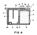
- the present invention is suitably applicable to an ink container which is divided into two spaces which communicate through a communicating opening, and one of which is provided with the ink supply opening and contains a ink absorption member.
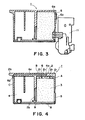
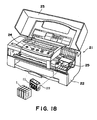
- the ink container 1 of this embodiment is mounted to a device with its bottom surface at the bottom, as shown in Figure 2.
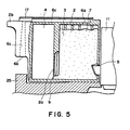
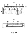
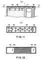
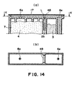
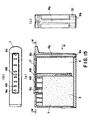
- the air vent path has an upper region provided by covering the groove 29 provided in an upper side wall of the ink cartridge 1 with the seal 17 as a sealing wall member, and a side region in a side wall extending in a direction of the gravity when the ink cartridge 1 is mounted on an ink jet recording apparatus.
- sealing of the above-described top side portion is effected by providing a projection 16 around the groove 29 and welding the seal member onto the projection.
- the ink droplet having entered the air vent path is more easily contacted to the wall constituting the air vent path in the top side region, so that the flow path resistance against the movement of the ink in the top side region is increased.
- the air vent particularly the outside opening end is disposed at a position where the paper dust does not easily enter, so that the opening is protected from being clogged by paper dust or dust.
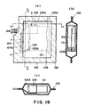
- Figure 20 shows process step of welding the seal member 104 to the ink supply port 102 and the air vent 103 of the main assembly 101.
- the main assembly 101 is moved away form the package 105 while rotating in the direction of arrow e about S point in the neighborhood of the first sealing portion a , as shown in Figure 21, (b).
- the main assembly 101 rotates in the direction of arrow e, as shown in Figure 21, (c) so that the separating direction of the first sealing portions from the collar rib 102A and the separating direction F1 become the same, that is, so as to facilitate the separating of the first sealing portion.
- the first sealing portion is separated.
Landscapes
- Engineering & Computer Science (AREA)
- Manufacturing & Machinery (AREA)
- Ink Jet (AREA)
- Packages (AREA)
- Closing Of Containers (AREA)
Claims (25)
- Tintenbehälter (1), der in einem Tintenstrahlgerät angeordnet werden kann, wobei das Tintenstrahlgerät einen Aufzeichnungskopf (11) mit einem Zuführelement zur Verbindung mit dem Tintenbehälter aufweist, wobei der Tintenbehälter aufweist:wobei der Luftlochabschnitt (6) eine innenseitige Öffnung (6a) aufweist, die in Fluidverbindung mit einem Innenraum der Aufnahmekammer (3) ist, eine außenseitige Öffnung (6b), die zu der Atmosphäre offen ist, und einen Fluidverbindungskanal (6c) in Fluidverbindung mit der innenseitigen Öffnung (6a) und der außenseitigen Öffnung (6b),eine Bodenfläche (8; D), welche eine untere Position einnimmt, wenn der Tintenbehälter in dem Tintenstrahlgerät angeordnet wird,eine Tintenabsorptionsmaterial-Aufnahmekammer (3) zum Aufnehmen eines Tintenabsorptionsmaterials (7) zum Vorhalten von Tinte zum Zuführen zu dem Aufzeichnungskopf,eine Tintenzuführöffnung (5) in Fluidverbindung mit der Aufnahmekammer (3) und angrenzend an die Aufnahmekammer zur Verbindung mit dem Zuführelement zum Zuführen der Tinte aus der Aufnahmekammer (3) zu dem Aufzeichnungskopf,einen Luftlochabschnitt (6) zur Fluidverbindung zwischen der Aufnahmekammer (3) und der Atmosphäre,
dadurch gekennzeichnet, daß:die außenseitige Öffnung (6b) eine Position einnimmt, die der Bodenfläche (8; D) näher ist als die durch die innenseitige Öffnung (6a) eingenommene. - Behälter gemäß Anspruch 1, wobei der Tintenbehälter (1) eine Seite oder mehrere Seiten aufweist, und wobei der Luftlochabschnitt (6) und die Tintenzuführöffnung (5) auf der gleichen der einen Seite oder mehrerer Seiten angeordnet sind.
- Behälter gemäß Anspruch 1, wobei der Tintenbehälter (1) eine Vielzahl von Seiten (A, B, C) aufweist, und wobei die innenseitige Öffnung (6a) des Luftlochabschnitts (6) in einer ersten der Vielzahl von Seiten (A, B, C) angeordnet ist, die Tintenzuführöffnung (5) in einer zweiten der Vielzahl von Seiten (A, B, C) angeordnet ist und die außenseitige Öffnung (6b) in einer dritten der Vielzahl von Seiten (A, B, C) angeordnet ist.
- Behälter gemäß Anspruch 1, wobei der Behälter ferner aufweist:wobei das Abdichtelement (104) von dem Tintenbehälter in einer Abtrennrichtung entfernt wird und von der Vielzahl der Anordnungsabschnitte (102A, 103A) entfernt wird,ein Abdichtelement (104), das an einer Vielzahl von Anordnungsabschnitten (102A, 103A) an Außenseiten des Tintenbehälters (101) abnehmbar angeordnet ist, wobei das Abdichtelement (104) einen ersten Abdichtabschnitt (A) zum Abdichten der Tintenzuführöffnung (102) aufweist, einen zweiten Abdichtabschnitt (B) zum Abdichten des Luftlochabschnitts (103) und einen Operationsabschnitt (C) zum Aufnehmen einer Abtrennkraft zum Entfernen des Abdichtelements (104),
wobei der erste Abdichtabschnitt (A) näher einem ersten der Vielzahl von Anordnungsabschnitten angeordnet ist, der erste der Vielzahl von Anordnungsabschnitten ein Anordnungsabschnitt (102A) ist, welcher einen Winkel in bezug auf die Abtrennrichtung ausbildet, der kleiner als ein Winkel zwischen der Abtrennrichtung und dem zweiten Abdichtabschnitt (103A) ist. - Behälter gemäß Anspruch 1, wobei die außenseitige Öffnung (6b) des Luftlochabschnitts (6) in einer Richtung zu der Bodenfläche (8) geöffnet ist.
- Behälter gemäß Anspruch 1, wobei der Fluidverbindungskanal (6c) eine Querschnittsfläche aufweist, welche zu der außenseitigen Öffnung (6b) allmählich größer wird.
- Behälter gemäß Anspruch 1, wobei der Fluidverbindungskanal (6c) einen Bereich aufweist, in welchem sich dessen Strömungswiderstand ändert.
- Behälter gemäß Anspruch 1, wobei die außenseitige Öffnung (6b) durch eine Vertiefung (31) ausgebildet ist, die sich in einer Breitenrichtung des Tintenbehälters (1) erstreckt.
- Behälter gemäß Anspruch 1, wobei die außenseitige Öffnung (6c) über der Bodenfläche (8) angeordnet ist.
- Behälter gemäß Anspruch 1, der ferner einen Tintenaufnahmeabschnitt (4) zum Aufnehmen von Tinte und eine Verbindungsöffnung (9) aufweist, wobei der Tintenaufnahmeabschnitt (4) durch die Verbindungsöffnung (9) mit dem Tintenabsorptionsmaterial-Aufnahmeabschnitt (3) in Fluidverbindung ist.
- Behälter gemäß Anspruch 1, wobei dann, wenn der Tintenbehälter in dem Tintenstrahlgerät angeordnet wird, die außenseitige Öffnung (6b) des Luftlochabschnitts (6) in einer Position in Gegenüberlage eines Teils des Aufzeichnungskopfs geöffnet ist.
- Behälter gemäß Anspruch 1, wobei das Tintenstrahlgerät ferner einen bewegbaren Schlitten aufweist, auf welchem der Tintenbehälter angeordnet werden kann, und wobei die außenseitige Öffnung (6b) des Luftlochabschnitts (6) in einer Position in Gegenüberlage eines Teils des Schlittens geöffnet ist.
- Behälter gemäß Anspruch 1, wobei der Tintenbehälter (1) Tinte enthält.
- Tintenbehälter zum Vorhalten von Tinte zur Zuführung zu einem Aufzeichnungskopf, der an einem Tintenstrahlgerät abnehmbar angeordnet ist, der aufweist:wobei der Luftlochabschnitt (6) eine innenseitige Öffnung (6a) aufweist, welche zu einem Innenraum des Tintenbehälters (1) offen ist, eine außenseitige Öffnung (6b), welche zu der Atmosphäre geöffnet ist, und einen Fluidverbindungskanal (6c) zur Herstellung der Fluidverbindung zwischen der innenseitigen Öffnung (6a) und der außenseitigen Öffnung (6b),eine Trennwand (2a), die einen Innenraum des Tintenbehälters (1) in eine erste Kammer (3) und in eine zweite Kammer (4) unterteilt, wobei die erste Kammer (3) ein Tintenabsorptionsmaterial (7) enthält und eine Tintenzuführöffnung (5) sowie einen Luftlochabschnitt (6) aufweist und die zweite Kammer (4) Tinte enthält,eine Verbindungsöffnung (9), die zwischen der Trennwand (2a) und einer Bodenfläche (8; D) des Behälters (1) ausgebildet ist und die Fluidverbindung zwischen der ersten Kammer (3) und der zweiten Kammer (4) herstellt,
dadurch gekennzeichnet, daß:dadurch, daß:der Luftlochabschnitt (6) ferner eine Abdeckung (6d) aufweist, welche einen Teil des Fluidverbindungskanals (6c) abdeckt und diesen dadurch ausbildet, unddie außenseitige Öffnung (6d) eine Position einnimmt, die der Bodenfläche (8; D) näher ist als die durch die innenseitige Öffnung (6a) eingenommene. - Behälter gemäß Anspruch 14, wobei der Tintenbehälter (1) eine Seite oder mehrere Seiten aufweist, und wobei der Luftlochabschnitt (6) und die Tintenzuführöffnung (5) auf der gleichen der einen Seite oder mehrerer Seiten angeordnet sind.
- Behälter gemäß Anspruch 14, wobei der Tintenbehälter eine Vielzahl von Seiten (A, B, C) aufweist, und wobei die innenseitige Öffnung (6a) des Luftlochabschnitts (6) in einer ersten der Vielzahl von Seiten (A, B, C) angeordnet ist, die Tintenzuführöffnung (5) in einer zweiten der Vielzahl von Seiten (A, B, C) angeordnet ist und die außenseitige Öffnung (6b) in einer dritten der Vielzahl von Seiten (A, B, C) angeordnet ist.
- Behälter gemäß Anspruch 14, wobei der Behälter ferner aufweist:wobei das Abdichtelement (104) von dem Tintenbehälter in einer Abtrennrichtung entfernt wird und von der Vielzahl der Anordnungsabschnitte (102A, 103A) entfernt wird,ein Abdichtelement (104), das an einer Vielzahl von Anordnungsabschnitten (102A, 103A) an Außenseiten des Tintenbehälters (101) abnehmbar angeordnet ist, wobei das Abdichtelement (104) einen ersten Abdichtabschnitt (A) zum Abdichten der Tintenzuführöffnung (102) aufweist, einen zweiten Abdichtabschnitt (B) zum Abdichten des Luftlochabschnitts (103) und einen Operationsabschnitt (C) zum Aufnehmen einer Abtrennkraft zum Entfernen des Abdichtelements (104),
wobei der erste Abdichtabschnitt (A) näher einem ersten der Vielzahl von Anordnungsabschnitten angeordnet ist, der erste der Vielzahl von Anordnungsabschnitten ein Anordnungsabschnitt (102A) ist, welcher einen Winkel in bezug auf die Abtrennrichtung ausbildet, der kleiner als ein Winkel zwischen der Abtrennrichtung und dem zweiten Abdichtabschnitt (103A) ist. - Behälter gemäß Anspruch 14, wobei die außenseitige Öffnung (6b) des Luftlochabschnitts (6) in eine Richtung zu der Bodenfläche (8) geöffnet ist.
- Behälter gemäß Anspruch 14, wobei der Fluidverbindungskanal (6c) eine Querschnittsfläche aufweist, welche zu der außenseitigen Öffnung (6b) allmählich größer wird.
- Behälter gemäß Anspruch 14, wobei der Verbindungskanal (6c) einen Bereich aufweist, in welchem sich dessen Strömungswiderstand ändert.
- Behälter gemäß Anspruch 14, wobei die außenseitige Öffnung (6b) mit einer Vertiefung (31) versehen ist, die sich in einer Breitenrichtung des Tintenbehälters (1) erstreckt.
- Behälter gemäß Anspruch 14, wobei die außenseitige Öffnung (6b) über der Bodenfläche (8) angeordnet ist.
- Behälter gemäß Anspruch 14, wobei der Tintenbehälter (1) Tinte enthält.
- Behälter gemäß Anspruch 14, wobei dann, wenn der Tintenbehälter in dem Tintenstrahlgerät angeordnet wird, die außenseitige Öffnung (6b) des Luftlochabschnitts (6) in einer Position in Gegenüberlage eines Teils des Aufzeichnungskopfs geöffnet ist.
- Behälter gemäß Anspruch 14, wobei das Tintenstrahlgerät ferner einen bewegbaren Schlitten aufweist, auf welchem der Tintenbehälter angeordnet werden kann, und wobei die außenseitige Öffnung (6b) des Luftlochabschnitts (6) in einer Position in Gegenüberlage eines Teils des Schlittens geöffnet ist.
Priority Applications (1)
| Application Number | Priority Date | Filing Date | Title |
|---|---|---|---|
| EP02004862A EP1223038A3 (de) | 1995-04-24 | 1996-04-23 | Tintenbehälter und Verfahren zu dessen Herstellung |
Applications Claiming Priority (9)
| Application Number | Priority Date | Filing Date | Title |
|---|---|---|---|
| JP9852495 | 1995-04-24 | ||
| JP98524/95 | 1995-04-24 | ||
| JP9852495A JP3119425B2 (ja) | 1995-04-24 | 1995-04-24 | インクタンク |
| JP13373995A JP3176254B2 (ja) | 1995-05-31 | 1995-05-31 | インクカートリッジ、該インクカートリッジを複数備えたインクジェット記録装置 |
| JP133739/95 | 1995-05-31 | ||
| JP13373995 | 1995-05-31 | ||
| JP29711395 | 1995-11-15 | ||
| JP29711395A JP3202560B2 (ja) | 1995-11-15 | 1995-11-15 | インクカートリッジ |
| JP297113/95 | 1995-11-15 |
Related Child Applications (1)
| Application Number | Title | Priority Date | Filing Date |
|---|---|---|---|
| EP02004862A Division EP1223038A3 (de) | 1995-04-24 | 1996-04-23 | Tintenbehälter und Verfahren zu dessen Herstellung |
Publications (3)
| Publication Number | Publication Date |
|---|---|
| EP0739741A2 EP0739741A2 (de) | 1996-10-30 |
| EP0739741A3 EP0739741A3 (de) | 1999-02-03 |
| EP0739741B1 true EP0739741B1 (de) | 2003-07-30 |
Family
ID=27308700
Family Applications (2)
| Application Number | Title | Priority Date | Filing Date |
|---|---|---|---|
| EP96106379A Expired - Lifetime EP0739741B1 (de) | 1995-04-24 | 1996-04-23 | Tintenbehälter und Verfahren zu dessen Herstellung |
| EP02004862A Withdrawn EP1223038A3 (de) | 1995-04-24 | 1996-04-23 | Tintenbehälter und Verfahren zu dessen Herstellung |
Family Applications After (1)
| Application Number | Title | Priority Date | Filing Date |
|---|---|---|---|
| EP02004862A Withdrawn EP1223038A3 (de) | 1995-04-24 | 1996-04-23 | Tintenbehälter und Verfahren zu dessen Herstellung |
Country Status (10)
| Country | Link |
|---|---|
| US (3) | US5953030A (de) |
| EP (2) | EP0739741B1 (de) |
| KR (1) | KR100190414B1 (de) |
| CN (1) | CN1113750C (de) |
| AT (1) | ATE246090T1 (de) |
| AU (1) | AU692079B2 (de) |
| CA (1) | CA2174679C (de) |
| DE (1) | DE69629233T2 (de) |
| MX (1) | MX9601517A (de) |
| SG (2) | SG97917A1 (de) |
Cited By (1)
| Publication number | Priority date | Publication date | Assignee | Title |
|---|---|---|---|---|
| WO2008130928A1 (en) * | 2007-04-18 | 2008-10-30 | Hewlett-Packard Development Company, L.P. | Fluid cartridge for a fluid supply system |
Families Citing this family (50)
| Publication number | Priority date | Publication date | Assignee | Title |
|---|---|---|---|---|
| CA2100977C (en) * | 1992-07-24 | 2000-02-08 | Noribumi Koitabashi | Ink container, ink and ink jet recording apparatus using ink container |
| JPH10138507A (ja) | 1996-11-14 | 1998-05-26 | Seiko Epson Corp | インクジェット式記録装置用インクカートリッジの製造方法 |
| EP0845362B1 (de) * | 1996-11-15 | 2003-10-01 | Canon Kabushiki Kaisha | Behälter zum Ausbringen von Flüssigkeit |
| MX9801290A (es) | 1997-02-19 | 1998-11-30 | Canon Cabushiki Kaisha | Envase de liquido para cabeza de chorron de tinta. |
| JPH10250111A (ja) * | 1997-03-17 | 1998-09-22 | Brother Ind Ltd | インクカートリッジの包装体 |
| JP2878233B2 (ja) * | 1997-04-09 | 1999-04-05 | 新潟日本電気株式会社 | インクカートリッジ |
| US6738096B1 (en) * | 1998-07-10 | 2004-05-18 | Silverbrook Research Pty Ltd | Low-cost disposable camera including print media carrying indication of postage paid |
| US7466341B2 (en) * | 1997-07-15 | 2008-12-16 | Silverbrook Research Pty Ltd | Disposable camera with destructive casing |
| US7832817B2 (en) * | 1997-07-15 | 2010-11-16 | Silverbrook Research Pty Ltd | Recyclable printing device with tamper protection |
| JP3880232B2 (ja) | 1997-12-25 | 2007-02-14 | キヤノン株式会社 | 液体供給方法、該液体供給方法を用いる液体供給システム、インクタンク |
| US6270207B1 (en) * | 1998-03-30 | 2001-08-07 | Brother Kogyo Kabushiki Kaisha | Ink cartridge and remaining ink volume detection method |
| JP3592112B2 (ja) | 1998-12-24 | 2004-11-24 | キヤノン株式会社 | 液体供給システム、液体収納容器、およびヘッドカートリッジ |
| JP3745161B2 (ja) | 1999-04-15 | 2006-02-15 | キヤノン株式会社 | 液体収納容器 |
| USD446545S1 (en) | 1999-12-22 | 2001-08-14 | Nec Corporation | Ink cartridge |
| USD441787S1 (en) | 2000-02-08 | 2001-05-08 | Lexmark International, Inc. | Ink cartridge for printer |
| USD437611S1 (en) | 2000-02-08 | 2001-02-13 | Lexmark International, Inc. | Ink cartridge for printer |
| CN1280103C (zh) * | 2000-02-16 | 2006-10-18 | 精工爱普生株式会社 | 喷墨打印机用连接组件及喷墨打印机 |
| JP2002001988A (ja) | 2000-04-18 | 2002-01-08 | Canon Aptex Inc | インクタンクおよびインクジェットカートリッジ |
| USD442990S1 (en) | 2000-07-07 | 2001-05-29 | Barouh Eaton Allen Corp. | Cover for color ink cartridge |
| USD442626S1 (en) | 2000-07-07 | 2001-05-22 | Barouh Eaton Allen Corp. | Cover for ink cartridge |
| US6254226B1 (en) * | 2000-07-14 | 2001-07-03 | Xerox Corporation | Liquid ink cartridge with recessed fill hole and ink tank vent |
| US6250749B1 (en) * | 2000-07-14 | 2001-06-26 | Xerox Corporation | Ink cartridge with overflow conduit |
| US6254227B1 (en) * | 2000-07-14 | 2001-07-03 | Xerox Corporation | Ink cartridge with spillover dam |
| JP3667295B2 (ja) * | 2001-05-10 | 2005-07-06 | キヤノン株式会社 | インクタンク |
| JP3774675B2 (ja) * | 2001-05-10 | 2006-05-17 | キヤノン株式会社 | パッケージ |
| US6447109B1 (en) | 2001-07-13 | 2002-09-10 | Xerox Corporation | Liquid ink cartridge and improved filling method |
| KR100438702B1 (ko) * | 2001-09-27 | 2004-07-05 | 삼성전자주식회사 | 잉크 카트리지 |
| KR100421972B1 (ko) * | 2002-05-16 | 2004-03-11 | 삼성전자주식회사 | 잉크 카트리지 |
| JP2004188720A (ja) * | 2002-12-10 | 2004-07-08 | Canon Inc | 液体収納容器 |
| US7052121B2 (en) * | 2002-12-10 | 2006-05-30 | Seiko Epson Corporation | Ink cartridge and ink jet printer |
| JP2005153506A (ja) * | 2003-11-07 | 2005-06-16 | Canon Finetech Inc | インクタンクパッケージおよびインクタンクパッケージの開封方法 |
| US7258434B2 (en) * | 2003-11-24 | 2007-08-21 | Lexmark International, Inc. | Inkjet printheads having multiple label placement positions for air diffusion vents |
| CN1217801C (zh) * | 2003-11-28 | 2005-09-07 | 珠海天威飞马打印耗材有限公司 | 喷墨打印机墨盒 |
| JP2006088650A (ja) * | 2004-09-27 | 2006-04-06 | Canon Inc | インクタンク、インクジェット記録装置、およびインクタンクの装着方法 |
| US20070035596A1 (en) * | 2005-08-10 | 2007-02-15 | Lexmark International, Inc. | Ink jet cartridge |
| US7726791B2 (en) * | 2006-03-31 | 2010-06-01 | Lexmark International, Inc. | Conduit construction using films |
| US20070246146A1 (en) * | 2006-04-19 | 2007-10-25 | Lexmark International, Inc. | Perforated and/or pointed sealing film for easy peel inkjet printhead and ink tank system applications |
| USD570905S1 (en) | 2006-09-08 | 2008-06-10 | Kenneth Yuen | Ink cartridge |
| US7419254B1 (en) | 2007-01-30 | 2008-09-02 | Brother Kogyo Kabushiki Kaisha | Ink cartridges |
| US20080204527A1 (en) * | 2007-02-28 | 2008-08-28 | Kenneth Yuen | Ink cartridge |
| US8025378B2 (en) * | 2007-03-28 | 2011-09-27 | Brother Kogyo Kabushiki Kaisha | Ink cartridges |
| US7938523B2 (en) * | 2007-06-13 | 2011-05-10 | Lexmark International, Inc. | Fluid supply tank ventilation for a micro-fluid ejection head |
| DE102007055161A1 (de) * | 2007-11-19 | 2009-05-20 | Pelikan Hardcopy Production Ag | Tintenpatrone, insbesondere für einen Tintenstrahldrucker |
| JP6163966B2 (ja) * | 2013-08-26 | 2017-07-19 | セイコーエプソン株式会社 | 液体収容容器およびその蓋体 |
| JP6476888B2 (ja) | 2015-01-19 | 2019-03-06 | ブラザー工業株式会社 | タンク |
| JP6955767B2 (ja) | 2015-07-31 | 2021-10-27 | カティーバ, インコーポレイテッド | インク送達システムおよび方法 |
| JP6685697B2 (ja) * | 2015-10-30 | 2020-04-22 | キヤノン株式会社 | インクタンク及びインクジェット記録装置 |
| EP3386758A4 (de) * | 2015-12-11 | 2019-08-07 | Hewlett-Packard Development Company, L.P. | Zusammenklappbarer behälter und sensor |
| JP7504665B2 (ja) * | 2020-05-28 | 2024-06-24 | キヤノン株式会社 | 液体収容容器 |
| JP7686443B2 (ja) * | 2021-04-28 | 2025-06-02 | キヤノン株式会社 | 液体収容容器および液体吐出装置 |
Family Cites Families (31)
| Publication number | Priority date | Publication date | Assignee | Title |
|---|---|---|---|---|
| US4065335A (en) * | 1975-07-28 | 1977-12-27 | Van Dyk Research Corporation | Process for manufacturing a xerographic toner cartridge |
| JP2510083B2 (ja) * | 1984-07-09 | 1996-06-26 | キヤノン株式会社 | インクジエツト記録装置 |
| US5231416A (en) * | 1988-11-09 | 1993-07-27 | Canon Kabushiki Kaisha | Container for ink jet head and recovering method of ink jet head using container |
| US5244087A (en) * | 1989-05-01 | 1993-09-14 | Canon Kabushiki Kaisha | Container for accommodating ink jet head cartridge |
| CA2025561C (en) * | 1989-09-18 | 1995-07-11 | Seiichiro Karita | Recording head with cover |
| EP0424133B1 (de) * | 1989-10-20 | 1995-03-22 | Canon Kabushiki Kaisha | Kassette mit Tintenvorratsbehälter auf einem Farbstrahlgerät aufstellbar |
| AU6774790A (en) * | 1989-12-06 | 1991-06-13 | Canon Kabushiki Kaisha | Package for ink jet cartridge |
| JP3169958B2 (ja) * | 1990-10-05 | 2001-05-28 | セイコーエプソン株式会社 | インクタンク |
| US5159348A (en) * | 1990-10-29 | 1992-10-27 | Xerox Corporation | Ink jet printing apparatus |
| EP0514632B1 (de) * | 1991-03-08 | 1997-06-04 | Canon Kabushiki Kaisha | Tintenstrahlaufzeichnungskopf und Schützverfahren dafür |
| JPH0516387A (ja) * | 1991-07-15 | 1993-01-26 | Canon Inc | インクジエツトカートリツジ用パツケージ |
| US5363130A (en) * | 1991-08-29 | 1994-11-08 | Hewlett-Packard Company | Method of valving and orientation sensitive valve including a liquid for controlling flow of gas into a container |
| JP2651759B2 (ja) * | 1991-08-29 | 1997-09-10 | シャープ株式会社 | 現像カートリツジの包装方法およびこれに利用される包装袋 |
| JP3192716B2 (ja) * | 1991-12-11 | 2001-07-30 | キヤノン株式会社 | インクカートリッジ用パッケージ |
| CA2084708C (en) * | 1991-12-11 | 1997-11-25 | Hiromitsu Hirabayashi | Ink jet recording apparatus and carriage mechanism therefor |
| US5477963A (en) * | 1992-01-28 | 1995-12-26 | Seiko Epson Corporation | Ink-jet recording apparatus and ink tank cartridge therefor |
| EP0562717B1 (de) * | 1992-02-24 | 1999-04-21 | Canon Kabushiki Kaisha | Ein Flüssigkeitsbehälter, eine Tintenstrahlpatrone mit einem Flüssigkeitsbehälter und ein Tintenstrahl- Aufzeichnungsgerät mit derartiger Patrone |
| JP3148005B2 (ja) * | 1992-06-16 | 2001-03-19 | キヤノン株式会社 | 記録カートリッジおよびインクジェット記録装置 |
| US5619238A (en) * | 1992-07-24 | 1997-04-08 | Canon Kabushiki Kaisha | Method of making replaceable ink cartridge |
| CA2100977C (en) * | 1992-07-24 | 2000-02-08 | Noribumi Koitabashi | Ink container, ink and ink jet recording apparatus using ink container |
| CA2272155C (en) * | 1992-07-31 | 2004-05-25 | Canon Kabushiki Kaisha | Liquid storing container for recording apparatus |
| KR970004231B1 (ko) * | 1992-10-02 | 1997-03-26 | 캐논 가부시끼가이샤 | 잉크 공급기구, 이러한 기구를 구비한 잉크제트 카트리지 및 이러한 기구를 구비한 잉크제트 기록장치 |
| DE69414296T2 (de) * | 1993-05-03 | 1999-03-25 | Hewlett-Packard Co., Palo Alto, Calif. | Rahmen aus zwei Materialien mit verschiedenen Eigenschaften für thermischem Tintenstrahldruckkopf |
| JP3284352B2 (ja) * | 1993-05-25 | 2002-05-20 | キヤノン株式会社 | インクジェット記録ヘッドの収納容器 |
| ATE169566T1 (de) * | 1993-05-25 | 1998-08-15 | Canon Kk | Verpackungsbehälter sowie verfahren zu seiner öffnung |
| DE69430589T2 (de) * | 1993-06-29 | 2002-10-02 | Canon K.K., Tokio/Tokyo | Behälter für Flüssigkeit, Tintenstrahlkassette mit diesem Behälter für Flüssigkeit und Tintenstrahlapparat mit dieser Tintenstrahlkassette |
| US5600358A (en) * | 1993-06-30 | 1997-02-04 | Hewlett-Packard Company | Ink pen having a hydrophobic barrier for controlling ink leakage |
| DE4326564C2 (de) * | 1993-08-07 | 1998-05-28 | Eastman Kodak Co | Düsenabdeckung für einen Tintendruckkopf und Verfahren zum Aufbringen derselben |
| US5479968A (en) * | 1993-08-16 | 1996-01-02 | Xerox Corporation | Ink filling apparatus and method for filling ink cartridges |
| JPH0839831A (ja) | 1994-05-23 | 1996-02-13 | Canon Inc | インクタンクカートリッジ及び該タンクに対するインク充填器 |
| DE69511461T2 (de) * | 1994-05-31 | 2000-04-13 | Canon K.K., Tokio/Tokyo | Austauschbare Tintenpatrone mit Verschlussstruktur |
-
1996
- 1996-04-19 US US08/636,766 patent/US5953030A/en not_active Expired - Lifetime
- 1996-04-22 CA CA002174679A patent/CA2174679C/en not_active Expired - Fee Related
- 1996-04-23 DE DE69629233T patent/DE69629233T2/de not_active Expired - Lifetime
- 1996-04-23 EP EP96106379A patent/EP0739741B1/de not_active Expired - Lifetime
- 1996-04-23 MX MX9601517A patent/MX9601517A/es unknown
- 1996-04-23 EP EP02004862A patent/EP1223038A3/de not_active Withdrawn
- 1996-04-23 AT AT96106379T patent/ATE246090T1/de not_active IP Right Cessation
- 1996-04-23 AU AU50854/96A patent/AU692079B2/en not_active Ceased
- 1996-04-24 SG SG200004443A patent/SG97917A1/en unknown
- 1996-04-24 SG SG1996009389A patent/SG74560A1/en unknown
- 1996-04-24 KR KR1019960012664A patent/KR100190414B1/ko not_active Expired - Lifetime
- 1996-04-24 CN CN96105455A patent/CN1113750C/zh not_active Expired - Fee Related
-
1998
- 1998-11-03 US US09/184,645 patent/US6302532B1/en not_active Expired - Lifetime
-
2001
- 2001-07-13 US US09/903,708 patent/US6478416B2/en not_active Expired - Fee Related
Cited By (1)
| Publication number | Priority date | Publication date | Assignee | Title |
|---|---|---|---|---|
| WO2008130928A1 (en) * | 2007-04-18 | 2008-10-30 | Hewlett-Packard Development Company, L.P. | Fluid cartridge for a fluid supply system |
Also Published As
| Publication number | Publication date |
|---|---|
| AU692079B2 (en) | 1998-05-28 |
| US6302532B1 (en) | 2001-10-16 |
| US6478416B2 (en) | 2002-11-12 |
| CN1113750C (zh) | 2003-07-09 |
| DE69629233T2 (de) | 2004-04-15 |
| SG97917A1 (en) | 2003-08-20 |
| DE69629233D1 (de) | 2003-09-04 |
| US5953030A (en) | 1999-09-14 |
| KR100190414B1 (ko) | 1999-06-01 |
| KR960037296A (ko) | 1996-11-19 |
| AU5085496A (en) | 1996-11-14 |
| MX9601517A (es) | 1997-04-30 |
| CA2174679C (en) | 2001-02-06 |
| US20010040614A1 (en) | 2001-11-15 |
| EP1223038A3 (de) | 2002-07-24 |
| EP0739741A3 (de) | 1999-02-03 |
| EP0739741A2 (de) | 1996-10-30 |
| SG74560A1 (en) | 2000-08-22 |
| CN1139621A (zh) | 1997-01-08 |
| EP1223038A2 (de) | 2002-07-17 |
| ATE246090T1 (de) | 2003-08-15 |
| CA2174679A1 (en) | 1996-10-25 |
Similar Documents
| Publication | Publication Date | Title |
|---|---|---|
| CA2174679C (en) | Ink container and manufacturing method for the same | |
| EP0829363B1 (de) | Tintenbehälter, Halter zum lösbaren Halten eines Tintenbehälters und Tintenbehälterabdeckung | |
| KR100515854B1 (ko) | 잉크 카트리지 | |
| KR100235282B1 (ko) | 잉크제트 인쇄 시스템과 잉크제트 프린트 카트리지를 이용한 잉크보충방법 | |
| US6123420A (en) | Container with negative pressure producing material | |
| JP3627147B2 (ja) | インクカートリッジ | |
| US6039441A (en) | Ink jet recording unit | |
| KR100266931B1 (ko) | 잉크제트인쇄시스템및프린트카트리지에잉크를재충전하는방법 | |
| KR100235283B1 (ko) | 잉크제트 인쇄 시스템과 잉크제트 프린트 카트리지 충전방법 | |
| US6786584B2 (en) | Ink housing device reliably preventing ink leakage | |
| AU731524B2 (en) | Ink container and manufacturing method for the same | |
| JP7536488B2 (ja) | 液体補給容器及び液体補給構造 | |
| JP3224180B2 (ja) | インク記録ヘッド用インクタンクのインク再充填方法および再充填装置 | |
| JPH0768778A (ja) | ヘッドカートリッジおよびプリント装置 | |
| JP2002178544A (ja) | 液体収納容器、および該液体収納容器の結合解除方法 | |
| JPH09131886A (ja) | インク記録ヘッド用インクタンクのインク再充填装置 | |
| AU725378B2 (en) | Ink jet cartridge, ink jet head and printer | |
| JPH0344531Y2 (de) | ||
| GB2305634A (en) | Ink jet cartridge, ink jet head and printer | |
| CN1389350A (zh) | 油墨容器及其制造方法 | |
| GB2297524A (en) | Ink jet cartridge, ink jet head and printer |
Legal Events
| Date | Code | Title | Description |
|---|---|---|---|
| PUAI | Public reference made under article 153(3) epc to a published international application that has entered the european phase |
Free format text: ORIGINAL CODE: 0009012 |
|
| 17P | Request for examination filed |
Effective date: 19960423 |
|
| AK | Designated contracting states |
Kind code of ref document: A2 Designated state(s): AT BE CH DE DK ES FI FR GB GR IE IT LI LU NL PT SE |
|
| PUAL | Search report despatched |
Free format text: ORIGINAL CODE: 0009013 |
|
| AK | Designated contracting states |
Kind code of ref document: A3 Designated state(s): AT BE CH DE DK ES FI FR GB GR IE IT LI LU NL PT SE |
|
| 17Q | First examination report despatched |
Effective date: 20010111 |
|
| GRAH | Despatch of communication of intention to grant a patent |
Free format text: ORIGINAL CODE: EPIDOS IGRA |
|
| GRAH | Despatch of communication of intention to grant a patent |
Free format text: ORIGINAL CODE: EPIDOS IGRA |
|
| GRAA | (expected) grant |
Free format text: ORIGINAL CODE: 0009210 |
|
| AK | Designated contracting states |
Designated state(s): AT BE CH DE DK ES FI FR GB GR IE IT LI LU NL PT SE |
|
| PG25 | Lapsed in a contracting state [announced via postgrant information from national office to epo] |
Ref country code: NL Free format text: LAPSE BECAUSE OF FAILURE TO SUBMIT A TRANSLATION OF THE DESCRIPTION OR TO PAY THE FEE WITHIN THE PRESCRIBED TIME-LIMIT Effective date: 20030730 Ref country code: IT Free format text: LAPSE BECAUSE OF FAILURE TO SUBMIT A TRANSLATION OF THE DESCRIPTION OR TO PAY THE FEE WITHIN THE PRE;WARNING: LAPSES OF ITALIAN PATENTS WITH EFFECTIVE DATE BEFORE 2007 MAY HAVE OCCURRED AT ANY TIME BEFORE 2007. THE CORRECT EFFECTIVE DATE MAY BE DIFFERENT FROM THE ONE RECORDED.SCRIBED TIME-LIMIT Effective date: 20030730 Ref country code: FR Free format text: LAPSE BECAUSE OF NON-PAYMENT OF DUE FEES Effective date: 20030730 Ref country code: FI Free format text: LAPSE BECAUSE OF FAILURE TO SUBMIT A TRANSLATION OF THE DESCRIPTION OR TO PAY THE FEE WITHIN THE PRESCRIBED TIME-LIMIT Effective date: 20030730 Ref country code: BE Free format text: LAPSE BECAUSE OF FAILURE TO SUBMIT A TRANSLATION OF THE DESCRIPTION OR TO PAY THE FEE WITHIN THE PRESCRIBED TIME-LIMIT Effective date: 20030730 Ref country code: AT Free format text: LAPSE BECAUSE OF FAILURE TO SUBMIT A TRANSLATION OF THE DESCRIPTION OR TO PAY THE FEE WITHIN THE PRESCRIBED TIME-LIMIT Effective date: 20030730 |
|
| REG | Reference to a national code |
Ref country code: GB Ref legal event code: FG4D |
|
| REG | Reference to a national code |
Ref country code: CH Ref legal event code: EP |
|
| REG | Reference to a national code |
Ref country code: CH Ref legal event code: NV Representative=s name: ARNOLD & SIEDSMA AG |
|
| REG | Reference to a national code |
Ref country code: IE Ref legal event code: FG4D |
|
| REF | Corresponds to: |
Ref document number: 69629233 Country of ref document: DE Date of ref document: 20030904 Kind code of ref document: P |
|
| PG25 | Lapsed in a contracting state [announced via postgrant information from national office to epo] |
Ref country code: SE Free format text: LAPSE BECAUSE OF FAILURE TO SUBMIT A TRANSLATION OF THE DESCRIPTION OR TO PAY THE FEE WITHIN THE PRESCRIBED TIME-LIMIT Effective date: 20031030 Ref country code: GR Free format text: LAPSE BECAUSE OF FAILURE TO SUBMIT A TRANSLATION OF THE DESCRIPTION OR TO PAY THE FEE WITHIN THE PRESCRIBED TIME-LIMIT Effective date: 20031030 Ref country code: DK Free format text: LAPSE BECAUSE OF FAILURE TO SUBMIT A TRANSLATION OF THE DESCRIPTION OR TO PAY THE FEE WITHIN THE PRESCRIBED TIME-LIMIT Effective date: 20031030 |
|
| PG25 | Lapsed in a contracting state [announced via postgrant information from national office to epo] |
Ref country code: ES Free format text: LAPSE BECAUSE OF FAILURE TO SUBMIT A TRANSLATION OF THE DESCRIPTION OR TO PAY THE FEE WITHIN THE PRESCRIBED TIME-LIMIT Effective date: 20031110 |
|
| NLV1 | Nl: lapsed or annulled due to failure to fulfill the requirements of art. 29p and 29m of the patents act | ||
| PG25 | Lapsed in a contracting state [announced via postgrant information from national office to epo] |
Ref country code: PT Free format text: LAPSE BECAUSE OF FAILURE TO SUBMIT A TRANSLATION OF THE DESCRIPTION OR TO PAY THE FEE WITHIN THE PRESCRIBED TIME-LIMIT Effective date: 20031230 |
|
| PG25 | Lapsed in a contracting state [announced via postgrant information from national office to epo] |
Ref country code: LU Free format text: LAPSE BECAUSE OF NON-PAYMENT OF DUE FEES Effective date: 20040423 Ref country code: IE Free format text: LAPSE BECAUSE OF NON-PAYMENT OF DUE FEES Effective date: 20040423 |
|
| PLBE | No opposition filed within time limit |
Free format text: ORIGINAL CODE: 0009261 |
|
| STAA | Information on the status of an ep patent application or granted ep patent |
Free format text: STATUS: NO OPPOSITION FILED WITHIN TIME LIMIT |
|
| 26N | No opposition filed |
Effective date: 20040504 |
|
| EN | Fr: translation not filed | ||
| REG | Reference to a national code |
Ref country code: IE Ref legal event code: MM4A |
|
| REG | Reference to a national code |
Ref country code: CH Ref legal event code: PFA Owner name: CANON KABUSHIKI KAISHA Free format text: CANON KABUSHIKI KAISHA#3-30-2 SHIMOMARUKO#OHTA-KU, TOKYO (JP) -TRANSFER TO- CANON KABUSHIKI KAISHA#3-30-2 SHIMOMARUKO#OHTA-KU, TOKYO (JP) |
|
| PGFP | Annual fee paid to national office [announced via postgrant information from national office to epo] |
Ref country code: CH Payment date: 20130417 Year of fee payment: 18 |
|
| PGFP | Annual fee paid to national office [announced via postgrant information from national office to epo] |
Ref country code: GB Payment date: 20140414 Year of fee payment: 19 |
|
| PGFP | Annual fee paid to national office [announced via postgrant information from national office to epo] |
Ref country code: DE Payment date: 20140430 Year of fee payment: 19 |
|
| REG | Reference to a national code |
Ref country code: CH Ref legal event code: PL |
|
| PG25 | Lapsed in a contracting state [announced via postgrant information from national office to epo] |
Ref country code: CH Free format text: LAPSE BECAUSE OF NON-PAYMENT OF DUE FEES Effective date: 20140430 Ref country code: LI Free format text: LAPSE BECAUSE OF NON-PAYMENT OF DUE FEES Effective date: 20140430 |
|
| REG | Reference to a national code |
Ref country code: DE Ref legal event code: R119 Ref document number: 69629233 Country of ref document: DE |
|
| GBPC | Gb: european patent ceased through non-payment of renewal fee |
Effective date: 20150423 |
|
| PG25 | Lapsed in a contracting state [announced via postgrant information from national office to epo] |
Ref country code: GB Free format text: LAPSE BECAUSE OF NON-PAYMENT OF DUE FEES Effective date: 20150423 Ref country code: DE Free format text: LAPSE BECAUSE OF NON-PAYMENT OF DUE FEES Effective date: 20151103 |