EP0738930A2 - UV absorbierende und IR ausbleichbare Elemente - Google Patents
UV absorbierende und IR ausbleichbare Elemente Download PDFInfo
- Publication number
- EP0738930A2 EP0738930A2 EP96302792A EP96302792A EP0738930A2 EP 0738930 A2 EP0738930 A2 EP 0738930A2 EP 96302792 A EP96302792 A EP 96302792A EP 96302792 A EP96302792 A EP 96302792A EP 0738930 A2 EP0738930 A2 EP 0738930A2
- Authority
- EP
- European Patent Office
- Prior art keywords
- image
- wavelength
- imaging
- forming
- compound
- Prior art date
- Legal status (The legal status is an assumption and is not a legal conclusion. Google has not performed a legal analysis and makes no representation as to the accuracy of the status listed.)
- Withdrawn
Links
Images
Classifications
-
- G—PHYSICS
- G03—PHOTOGRAPHY; CINEMATOGRAPHY; ANALOGOUS TECHNIQUES USING WAVES OTHER THAN OPTICAL WAVES; ELECTROGRAPHY; HOLOGRAPHY
- G03F—PHOTOMECHANICAL PRODUCTION OF TEXTURED OR PATTERNED SURFACES, e.g. FOR PRINTING, FOR PROCESSING OF SEMICONDUCTOR DEVICES; MATERIALS THEREFOR; ORIGINALS THEREFOR; APPARATUS SPECIALLY ADAPTED THEREFOR
- G03F1/00—Originals for photomechanical production of textured or patterned surfaces, e.g., masks, photo-masks, reticles; Mask blanks or pellicles therefor; Containers specially adapted therefor; Preparation thereof
- G03F1/68—Preparation processes not covered by groups G03F1/20 - G03F1/50
-
- B—PERFORMING OPERATIONS; TRANSPORTING
- B41—PRINTING; LINING MACHINES; TYPEWRITERS; STAMPS
- B41M—PRINTING, DUPLICATING, MARKING, OR COPYING PROCESSES; COLOUR PRINTING
- B41M5/00—Duplicating or marking methods; Sheet materials for use therein
- B41M5/26—Thermography ; Marking by high energetic means, e.g. laser otherwise than by burning, and characterised by the material used
- B41M5/28—Thermography ; Marking by high energetic means, e.g. laser otherwise than by burning, and characterised by the material used using thermochromic compounds or layers containing liquid crystals, microcapsules, bleachable dyes or heat- decomposable compounds, e.g. gas- liberating
- B41M5/286—Thermography ; Marking by high energetic means, e.g. laser otherwise than by burning, and characterised by the material used using thermochromic compounds or layers containing liquid crystals, microcapsules, bleachable dyes or heat- decomposable compounds, e.g. gas- liberating using compounds undergoing unimolecular fragmentation to obtain colour shift, e.g. bleachable dyes
-
- G—PHYSICS
- G03—PHOTOGRAPHY; CINEMATOGRAPHY; ANALOGOUS TECHNIQUES USING WAVES OTHER THAN OPTICAL WAVES; ELECTROGRAPHY; HOLOGRAPHY
- G03C—PHOTOSENSITIVE MATERIALS FOR PHOTOGRAPHIC PURPOSES; PHOTOGRAPHIC PROCESSES, e.g. CINE, X-RAY, COLOUR, STEREO-PHOTOGRAPHIC PROCESSES; AUXILIARY PROCESSES IN PHOTOGRAPHY
- G03C7/00—Multicolour photographic processes or agents therefor; Regeneration of such processing agents; Photosensitive materials for multicolour processes
- G03C7/02—Direct bleach-out processes; Materials therefor; Preparing or processing such materials
-
- G—PHYSICS
- G03—PHOTOGRAPHY; CINEMATOGRAPHY; ANALOGOUS TECHNIQUES USING WAVES OTHER THAN OPTICAL WAVES; ELECTROGRAPHY; HOLOGRAPHY
- G03F—PHOTOMECHANICAL PRODUCTION OF TEXTURED OR PATTERNED SURFACES, e.g. FOR PRINTING, FOR PROCESSING OF SEMICONDUCTOR DEVICES; MATERIALS THEREFOR; ORIGINALS THEREFOR; APPARATUS SPECIALLY ADAPTED THEREFOR
- G03F7/00—Photomechanical, e.g. photolithographic, production of textured or patterned surfaces, e.g. printing surfaces; Materials therefor, e.g. comprising photoresists; Apparatus specially adapted therefor
- G03F7/004—Photosensitive materials
- G03F7/09—Photosensitive materials characterised by structural details, e.g. supports, auxiliary layers
- G03F7/095—Photosensitive materials characterised by structural details, e.g. supports, auxiliary layers having more than one photosensitive layer
-
- Y—GENERAL TAGGING OF NEW TECHNOLOGICAL DEVELOPMENTS; GENERAL TAGGING OF CROSS-SECTIONAL TECHNOLOGIES SPANNING OVER SEVERAL SECTIONS OF THE IPC; TECHNICAL SUBJECTS COVERED BY FORMER USPC CROSS-REFERENCE ART COLLECTIONS [XRACs] AND DIGESTS
- Y10—TECHNICAL SUBJECTS COVERED BY FORMER USPC
- Y10S—TECHNICAL SUBJECTS COVERED BY FORMER USPC CROSS-REFERENCE ART COLLECTIONS [XRACs] AND DIGESTS
- Y10S430/00—Radiation imagery chemistry: process, composition, or product thereof
- Y10S430/146—Laser beam
-
- Y—GENERAL TAGGING OF NEW TECHNOLOGICAL DEVELOPMENTS; GENERAL TAGGING OF CROSS-SECTIONAL TECHNOLOGIES SPANNING OVER SEVERAL SECTIONS OF THE IPC; TECHNICAL SUBJECTS COVERED BY FORMER USPC CROSS-REFERENCE ART COLLECTIONS [XRACs] AND DIGESTS
- Y10—TECHNICAL SUBJECTS COVERED BY FORMER USPC
- Y10T—TECHNICAL SUBJECTS COVERED BY FORMER US CLASSIFICATION
- Y10T428/00—Stock material or miscellaneous articles
- Y10T428/24—Structurally defined web or sheet [e.g., overall dimension, etc.]
- Y10T428/24802—Discontinuous or differential coating, impregnation or bond [e.g., artwork, printing, retouched photograph, etc.]
Definitions
- the invention relates to UV absorbing media which are bleachable by IR irradiation to provide images suitable for use as masks.
- image-forming media suitable for address by lasers, particularly media which require no wet processing.
- Such media are particularly useful in medical imaging, recording the output of digital radiographic equipment, CAT scanners, magnetic resonance scanners and ultrasound scanners on film or paper, and graphic arts imaging, producing contact films, colour proofs and printing plates. While some laser addressable media have been described, relatively few examples have been commercialised.
- productivity is an issue, since economics dictate that the same scanner should be used to output three conventional types of media, namely films, proofs and plates. The ability to provide two out of three of these media simultaneously would clearly increase productivity.
- US-A-4981765 and 5262275 and EP-A-0488530 disclose the thermal transfer of dyes or pigments directly onto the photosensitive coating of a printing plate or similar element so as to form an integral mask.
- UV/blue region refers to a portion of the spectrum ranging from about 340nm to about 480nm.
- “Bleaching” refers to a decrease in optical density either by elimination of the relevant absorption bands or by their shift to shorter wavelengths.
- the "first wavelength” is intended to reflect a range of wavelengths rather than a single precise wavelength.
- said compound may absorb at wavelengths between 340 and 410, with maximum absorption at 390 nm.
- the exposure of step (iv) may be made at any wavelength within the first absorption range, not merely at the maximum absorption wavelength within that range.
- This aspect of the invention further extends to a method of forming an image comprising the steps of:-
- red and infrared dyes are known to be suitable for this purpose, including cyanines, phthalocyanines, polymethines, oxonols, squarylium dyes, croconium dyes and diamine dication dyes.
- the dye (b) if the bleaching process requires the presence of acid, then the dye (b) preferably generates acid via laser photolysis.
- a thermal source of acid may be used in combination with a photothermal converting dye as described above).
- IR-absorbing dyes having acid-generating properties include the tetra-arylpolymethine (TAPM) dyes, which are described, for example, in US-A-5135842.
- Preferred examples have a nucleus of general formula IV :- where Ar 1 - Ar 4 are aryl groups which may be the same or different such that at least two of Ar 1 - Ar 4 have a tertiary amino group in the 4-position, and X is an anion.
- tertiary amino groups include dialkylamino groups, diarylamino groups, and cyclic substitutents such as pyrrolidino, morpholino or piperidino.
- the tertiary amino group may form part of a fused ring system, e.g., one or more of Ar 1 - Ar 4 may represent a julolidine group.
- the anion X is derived from a strong acid (e.g. HX should have a pKa of less than 3, preferably less than 1).
- Suitable identities for X include ClO 4 , BF 4 , CF 3 SO 3 , PF 6 , AsF 6 or SbF 6 .
- Such dyes are believed to form the acid HX on irradiation, and the effect appears to be particularly strong when not all of Ar 1 - Ar 4 are identical.
- amine cation radical dyes also known as immonium dyes, having counterions derived from strong acids, described for example in WO90/12342 and JP51-88016.
- diamine di-cation dyes (exemplified by the commercially available CyasorbTM IR165 (Glendale Protective Technologies, Inc.)), which have a nucleus of general formula V and absorb in the YAG laser wavelength range:- in which Ar 1 - Ar 4 and X have the same meaning as before.
- the preferred dyes are cationic dyes (i.e., they have a positive charge associated with the chromophore).
- examples include polymethine dyes, pyrylium dyes, cyanine dyes, diamine di-cation dyes, phenazinium dyes, phenoxazinium dyes, phenothiazinium dyes and acridinium dyes, but the most preferred dyes are the TAPM dyes of formula IV and the diamine di-cation dyes of formula V.
- the imaging elements of the invention may be prepared by dissolving the dye and the bleachable compound in a suitable solvent and coating the mixture on a transparent substrate.
- the substrate must be transparent from the near UV to the near infrared, and should be flexible, dimensionally stable and heat resistant.
- Conventional polyester base e.g., polyethyleneterephthalate and polyethylenenaphthalate of thickness 20 -200 microns
- Any conventional coating method may be used, such as spin coating, bar coating, roller coating or knife coating.
- Good results are obtained from a relatively high intensity laser exposure, e.g., of at least 10 23 photons/cm 2 /sec. For a laser diode emitting at 830nm, this corresponds approximately to an output of 0.1W focused to a 20 micron spot with a dwell time of about 1 microsecond. In the case of YAG laser exposure at 1064nm, a flux of at least 3X10 24 photons/cm 2 /sec is preferred, corresponding roughly to an output of 2W focused to a 20 micron spot with a dwell time of about 0.1 microsecond.
- any of the known scanning devices may be used, e.g. flat-bed scanners, external drum scanners or internal drum scanners.
- the element to be imaged is secured to the drum or bed (e.g., by vacuum hold-down) and the laser beam is focused to a spot (e.g., of about 20 microns diameter) on the absorbing layer.
- This spot is scanned over the entire area to be imaged while the laser output is modulated in accordance with electronically stored image information.
- Two or more lasers may scan different areas of the element simultaneously, and if necessary, the output of two or more lasers may be combined optically into a single spot of higher intensity.
- Such resists may be positive-acting (photosolubilising) or negative-acting (photoinsolubilising), or may be susceptible to peel-apart development as described below.
- the element is first exposed as described above to form an image in the first imaging medium. This is followed by flood exposure from a suitable source (e.g., a metal halide lamp or mercury lamp).
- a suitable source e.g., a metal halide lamp or mercury lamp.
- the exposure may also be effected by laser scanning at the appropriate wavelength, with the entire mask surface scanned by the laser. Areas of the first imaging medium which did not receive exposure in the first step remain opaque and block the passage of light during the flood exposure. Conversely, areas that did receive exposure in the first step become transparent, and permit passage of light in the flood exposure.
- the flood exposure results in the second imaging medium undergoing an imagewise irradiation that duplicates the pattern formed in the first imaging medium by the first exposure.
- the final step is processing by any method suitable for developing and fixing the image formed in the second imaging medium.
- the exposed (or unexposed) areas may be washed off by a suitable developer, or a peel-apart process may reveal the final image.
- This embodiment has the advantage of a single-sheet construction, with no need for a vacuum frame in the final exposure. Because the mask image may be generated in close proximity to the UV/blue sensitive medium, high resolution imaging of the latter is possible, without the optical artifacts that may arise from contacting two sheets.
- first imaging medium and second imaging medium may vary depending on whether the substrate is opaque or transparent.
- the first (mask forming) imaging medium must be coated on top of the photosensitive layer of the plate, and exposure must take place from that side.
- a barrier layer on top of the conventional plate coating prior to coating the mask forming chemistry.
- Water-soluble polymers such as gelatin or polvinylalcohol are preferred barrier materials, e.g., at a dry thickness of 1 - 5 microns.
- the mask-forming chemistry must be either on the back side of the substrate, or between the substrate and the photosensitive layer.
- Conventional proofing elements of this type may comprise (in sequence) a transparent substrate, a photosensitive layer, a coloured layer and an adhesive layer.
- the photosensitive and coloured layers may be combined in a single layer, and other layers, such as barrier layers or release layers may also be present, depending on the particular construction.
- conventional materials of this type may be first laminated to a reflective base, such as white paper or card, then flood exposed through a contact mask before or after removing the transparent substrate. Strippable or non-strippable antihalation layers may also be associated with the photosensitive medium.
- Proofing elements in accordance with this aspect of the invention differ from their conventional counterparts only in that the mask-forming chemistry is coated either on the back side of the transparent substrate or between the transparent substrate and the photosensitive layer. After lamination to a reflective base, the transparent substrate is left in place and the mask is generated by long wavelength exposure as described previously. After flood exposure through the mask, the transparent substrate is peeled away. In a peel-apart element, this develops the image, otherwise conventional wet development is carried out.
- the mask-forming chemistry is more convenient to coat the mask-forming chemistry on the back of the transparent substrate, as existing products may be modified with the minimum of disruption to the manufacturing process.
- various advantages may stem from coating the mask-forming chemistry between the substrate and photosensitive layer. Firstly, the mask is generated immediately adjacent the photosensitive layer, which makes for high resolution and eliminates optical distortions caused by the thickness of the substrate. Secondly, the Dmin areas of the mask seldom bleach to zero optical density, and the residual absorption can provide an antihalation effect, leading to improved resolution, dot gain control and exposure latitude, as described in EP-A-165030.
- the oxonol dyes provide optical density in the visible region (400 - 700 nm), and by combining oxonols with appropriate absorption characteristics, a neutral black can be obtained.
- the oxonols bleach cleanly during laser exposure along with the compound of formula III. Surprisingly, there is no significant speed loss due to the additional presence of the oxonols. The extent of bleaching varies with the intensity and/or duration of laser exposure, and so continuous tone imaging is possible.
- oxonol bleaching The mechanism of the oxonol bleaching is not well understood. Coatings comprising a dye of formula IV or V and one or more oxonols undergo partial bleaching on laser exposure, but the additional presence of a compound of formula III provides much more rapid and complete bleaching.
- Suitable oxonol dyes are of the type disclosed in US-A-4,701,402, and specific examples include:
- a second manner in which the basic construction may be elaborated to provide broader utility involves the inclusion of a thermally transferable colourant layer, and use of the resulting material as a laser addressable thermal transfer donor.
- the generation of colour images by transfer of a colourant from a donor to a receptor in response to laser irradiation is well known.
- By successive transfer of yellow, magenta, cyan and black images from the appropriate donors to a common receptor full colour images of high quality, suitable for proofing, may be obtained (as described in WO90/12342, US-A-5,171,650, and EP-A-0602893.
- mass transfer media do not necessarily transfer all of the colourant from exposed areas of the donor.
- mass transfer media do not necessarily transfer all of the colourant from exposed areas of the donor.
- transfer occurs by the "melt-stick" mechanism, there is a tendency for a significant residue to remain on the exposed parts of the donor. This does not affect the quality of the image on the receptor, but if the colourant is UV-absorbing, or an inert absorber has been added, then use of the imaged donor as a mask will be hampered by a high Dmin.
- an imaging element comprising a substrate and an imaging medium comprising (a) a compound absorbing at a first wavelength in the UV/blue region and (b) a dye absorbing at a second wavelength which is longer than said first wavelength, irradiation of the medium at said second wavelength bleaching absorption of the compound (a) at the first wavelength, said imaging medium additionally comprising a thermally transferable colourant.
- an imaging method comprising the steps of:
- any of the known mass-transfer colourant systems may be used in this embodiment of the invention, including waxy pigmented layers (JP63-319192), ablative materials (WO90/12342, US-A-5,171,650) and binderless layers of vapour deposited dyes or pigments (International Patent Application PCT/GB92/01489).
- the preferred transferable colourant comprises a dispersion of pigment particles in a binder together with a fluorochemical additive, as described in EP-A-0602893.
- Materials in accordance with the present invention may be prepared simply by adding a bleachable UV/blue absorber to the laser transfer imaging media described therein.
- the UV/blue absorber may be present in the colourant layer or in a separate layer, but for optimum bleaching it should be in the same layer as the laser-absorbing dye.
- a further embodiment of the present invention provides enhanced productivity, combines the functions of a film and a printing plate.
- EP-A-0652483 describes laser addressable printing plates requiring no dissolution processing which comprise a substrate bearing an infrared-sensitive coating, which coating becomes relatively more hydrophillic on exposure to infrared radiation.
- the coating comprises an infrared absorber and a polymer having pendant hydrophobic groups which react under the action of heat and/or acid to form hydrophillic groups.
- the infrared absorber generates an acid by absorption of radiation and/or an additional source of acid is present in the coating.
- the preferred reactive polymer is a copolymer of tetrahydropyranyl methacrylate and a vinyl-functional alkoxysilane. Suitable substrates
- DRC(TM) Film - a negative-acting, high contrast graphic arts contact film supplied by 3M.
- This example demonstrates direct formation of UV masks by media in accordance with the invention.
- the resulting coating had an Optical Density (OD) of 2.8 at 380nm and 1.2 at 830nm. It was mounted on an external drum scanner and imaged by means of a laser diode (830nm, 100mW, 20 micron spot) scanned at 200cm/sec. In the exposed areas, the UV absorption was bleached to OD 0.6. The imaged element was placed in contact with a piece of DRC film and exposed to a 5 kW UV source in the conventional manner. After conventional processing, the DRC film bore a negative replica of the original image.
- OD Optical Density
- Elements 2 and 3 were prepared by the same method using the following formulation:- ButvarTM B76 (10wt% in MEK) - 5.5g Dye D1 - 0.1g Bleachable Compound - 0.6g
- This example demonstrates direct formation of UV masks by binderless media in accordance with the invention.
- Elements 4 - 7 were mounted on an external drum scanner and imaged by a laser diode (830nm, 110mW, focused to 20 micron spot), scanned at 200 cm/sec to write tracks on the media.
- Element 8 was mounted on an internal drum scanner and imaged by a YAG laser (1060nm, 2W, focused to 26 micron spot), scanned at 6400 cm/sec, to write tracks on the media.
- the optical densities at 360nm before and after exposure are recorded in the following table:- OD(initial) OD(final) Element 4 1.8 0.6 Element 5 1.8 0.6 Element 6 2.0 0.3 Element 7 1.8 0.6 Element 8 1.8 0.3
- Element 9 was prepared as before, using the following formulation:- MEK - 3.5g Ethanol - 0.5g Dye D4 - 0.05 Compound (3) - 0.025g Compound (4) - 0.05g Compound (5) - 0.3g
- the mixture was roll-milled in a brown bottle under dim light for 30 minutes prior to coating.
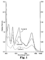
- the resulting film was neutral black in appearance, and had the absorption spectrum denoted by curve A in Figure 1 which represent a plot of optical density against wavelength.
- Curves B and C of Fig.1 denote the spectrum after laser exposure at scan speeds of 400 and 200 cm/sec respectively (830nm laser diode, 116mW, 20 micron spot). Clearly, bleaching occurs across the spectrum in proportion to the degree of exposure, indicating that the film is suitable for continuous tone imaging.
- This example demonstrates the simultaneous generation of matched film and proof images in accordance with the invention.
- Magenta and black millbases were prepared by dispersing 4g of the appropriate pigment chips in 32g MEK using a McCrone Micronising Mill.
- the pigment chips were prepared by standard procedures and comprised VAGH binder and either blue shade magenta pigment or black pigment in a weight ratio of 2:3.
- Element 10 was prepared by coating the following formulation as in previous examples:- Magenta millbase - 5.5g MEK - 5.5g Ethanol - 0.5g Dye D1 - 0.165g Compound 5 - 0.85g Magnesium nitrate - 0.05g FC - 0.025g
- a sample of the resulting donor sheet was assembled in face to face contact with a receptor sheet (VYNS coated paper) and mounted on an external drum scanner. Line scans were made at 200, 400, 600, 800 and 1000 cm/sec using an 830nm laser diode (100mW, 20 micron spot diameter), and transfer of magenta pigment was observed for scans at 600 cm/sec or less, although a residue of pigment remained in the exposed areas.
- the imaged donor was then used as a mask for the exposure of DRC film as before, and an accurate replica of the image formed on the receptor was obtained.
- Elements 11 and 12 were prepared in identical fashion from the following formulations:- Element 11 Element 12 Magenta millbase - 5.5g Black millbase 2.75g - MEK 2.5g 2.0g Ethanol 0.5g 1.0g IR165 0.06g 0.2g Compound (5) 0.35g 0.6g FC 0.125g 0.025g
- Element 11 was imaged in the same way as Element 10, with pigment transfer observed at scan speeds of 400 cm/sec or less.
- the imaged donor was again used successfully as a mask for the exposure of DRC film.
- Element 12 was contacted face to face with "Rainbow” (TM) thermal transfer imaging receptor (supplied by 3M) and imaged via a YAG laser as described for Element 8 in Example 2.
- TM thermal transfer imaging receptor
- a magenta image was formed on the receptor in response to the laser exposure (line width 17 microns).
- the imaged donor was again used to image DRC film, and the line width of the resulting DRC film image matched that of the receptor image.
- This example demonstrates simultaneous generation of film and plate images by media in accordance with the invention.
- Element 13 was prepared as for previous examples from the following formulation:- THP homopolymer (10wt% in MEK) - 5.5g Dye D1 - 0.15g Compound (1) - 0.20g
- the resulting coating was pale pink in colour and showed an intense UV absorption band (OD > 3.0).
- Laser imaging was carried out as before at scan rates in the range 200 - 800 cm/sec. Bleaching of both the IR and UV absorptions was seen in exposed areas.
- the imaged element was then used as a mask for the UV exposure of a positive acting peel-apart colour proofing element of the type described in EP-A-0601760. The result was a positive reproduction of the image present on Element 13.
- the imaged Element 13 was then mounted on an Apollo web-fed printing press, wiped with fountain solution (Mander Kidd), and inked with Van Son Black 40904 (rubber based) ink.
- the laser-exposed areas repelled the ink, whereas the non-exposed areas inked up cleanly within a few revolutions of the plate cylinder.
- 100 impressions on newsprint were taken without signs of wear or background toning.
- the printed images were an exact replica of the colour proof image.
Applications Claiming Priority (2)
| Application Number | Priority Date | Filing Date | Title |
|---|---|---|---|
| GB9508031 | 1995-04-20 | ||
| GBGB9508031.3A GB9508031D0 (en) | 1995-04-20 | 1995-04-20 | UV-absorbing media bleachable by IR-radiation |
Publications (2)
| Publication Number | Publication Date |
|---|---|
| EP0738930A2 true EP0738930A2 (de) | 1996-10-23 |
| EP0738930A3 EP0738930A3 (de) | 1997-11-26 |
Family
ID=10773248
Family Applications (1)
| Application Number | Title | Priority Date | Filing Date |
|---|---|---|---|
| EP96302792A Withdrawn EP0738930A3 (de) | 1995-04-20 | 1996-04-19 | UV absorbierende und IR ausbleichbare Elemente |
Country Status (4)
| Country | Link |
|---|---|
| US (1) | US5773170A (de) |
| EP (1) | EP0738930A3 (de) |
| JP (1) | JPH08292517A (de) |
| GB (1) | GB9508031D0 (de) |
Cited By (7)
| Publication number | Priority date | Publication date | Assignee | Title |
|---|---|---|---|---|
| US5843617A (en) * | 1996-08-20 | 1998-12-01 | Minnesota Mining & Manufacturing Company | Thermal bleaching of infrared dyes |
| US5945249A (en) | 1995-04-20 | 1999-08-31 | Imation Corp. | Laser absorbable photobleachable compositions |
| US6555283B1 (en) | 2000-06-07 | 2003-04-29 | Kodak Polychrome Graphics Llc | Imageable element and waterless printing plate |
| WO2005026836A2 (en) * | 2003-09-12 | 2005-03-24 | Tokyo Ohka Kogyo Co., Ltd. | Laminated photosensitive relief printing original plate and method for producing the relief printing plate |
| WO2007050778A2 (en) * | 2005-10-26 | 2007-05-03 | Hewlett-Packard Development Company, L.P. | Laser writable media substrate, and systems and methods of laser writng |
| WO2008021952A2 (en) * | 2006-08-11 | 2008-02-21 | Battelle Memorial Institute | Patterning compositions, masks, and methods |
| US7626185B2 (en) | 2006-08-11 | 2009-12-01 | Battelle Memorial Institute | Patterning compositions, masks, and methods |
Families Citing this family (19)
| Publication number | Priority date | Publication date | Assignee | Title |
|---|---|---|---|---|
| US5935758A (en) | 1995-04-20 | 1999-08-10 | Imation Corp. | Laser induced film transfer system |
| JP2003502449A (ja) | 1999-06-10 | 2003-01-21 | ハネウエル・インターナシヨナル・インコーポレーテツド | フォトリソグラフィ用スピンオンガラス反射防止コーティング |
| US6824879B2 (en) | 1999-06-10 | 2004-11-30 | Honeywell International Inc. | Spin-on-glass anti-reflective coatings for photolithography |
| US6607871B1 (en) * | 1999-09-27 | 2003-08-19 | Fuji Photo Film Co., Ltd. | Image recording medium |
| US7403651B2 (en) * | 2000-11-04 | 2008-07-22 | Leonhard Kurz Gmbh & Co. Kg | Plastic body in the form of a film, for example a transfer film or laminating film, or provided with such a film and a process for the production of a multi-color image on or in such a plastic body |
| DE10054803A1 (de) * | 2000-11-04 | 2002-05-29 | Kurz Leonhard Fa | Kunststoffkörper, insbesondere massiver Kunststoffkörper oder Folie, z. B. Transferfolie oder Laminierfolie sowie Verfahren zur Herstellung eines Mehrfarbenbildes auf oder in einem solchen Kunststoffkörper |
| KR20040066124A (ko) | 2001-11-15 | 2004-07-23 | 허니웰 인터내셔널 인코포레이티드 | 포토리소그라피용 스핀온 반사 방지 피막 |
| WO2003065122A1 (en) * | 2002-01-31 | 2003-08-07 | Scandinavian Micro Biodevices A/S | Method of joining a workpiece and a microstructure by light exposure |
| US6893796B2 (en) * | 2002-08-20 | 2005-05-17 | Kodak Polychrome Graphics Llc | Flexographic element having an integral thermally bleachable mask layer |
| US6962765B2 (en) * | 2003-10-20 | 2005-11-08 | Kodak Polychrome Graphics Llc | Laser-generated ultraviolet radiation mask |
| US8053159B2 (en) | 2003-11-18 | 2011-11-08 | Honeywell International Inc. | Antireflective coatings for via fill and photolithography applications and methods of preparation thereof |
| US7532226B2 (en) * | 2005-08-01 | 2009-05-12 | Hewlett-Packard Development Company, L.P. | Bleaching the background of a medium |
| US8642246B2 (en) | 2007-02-26 | 2014-02-04 | Honeywell International Inc. | Compositions, coatings and films for tri-layer patterning applications and methods of preparation thereof |
| US8557877B2 (en) | 2009-06-10 | 2013-10-15 | Honeywell International Inc. | Anti-reflective coatings for optically transparent substrates |
| JP5395023B2 (ja) * | 2010-09-29 | 2014-01-22 | 富士フイルム株式会社 | パターン形成方法、及び金属構造形成方法 |
| JP5395022B2 (ja) * | 2010-09-29 | 2014-01-22 | 富士フイルム株式会社 | パターン形成方法 |
| US8864898B2 (en) | 2011-05-31 | 2014-10-21 | Honeywell International Inc. | Coating formulations for optical elements |
| CN107001865B (zh) | 2014-11-12 | 2020-08-21 | 迪睿合株式会社 | 光固化类各向异性导电粘接剂、连接体的制造方法及电子部件的连接方法 |
| US10544329B2 (en) | 2015-04-13 | 2020-01-28 | Honeywell International Inc. | Polysiloxane formulations and coatings for optoelectronic applications |
Citations (7)
| Publication number | Priority date | Publication date | Assignee | Title |
|---|---|---|---|---|
| US3595658A (en) * | 1968-10-03 | 1971-07-27 | Little Inc A | Non-silver direct positive dye bleachout system using polymethine dyes and colored activators |
| EP0109772A2 (de) * | 1982-10-25 | 1984-05-30 | Minnesota Mining And Manufacturing Company | Fixierung von Aufzeichnungsmaterialien mit Tetra(hydrocarbyl)-Boratsalzen |
| EP0182332A2 (de) * | 1984-11-19 | 1986-05-28 | Hewlett-Packard Company | Behandlungsverfahren für integrierte Schaltungen durch Photolithographie |
| EP0331494A2 (de) * | 1988-03-02 | 1989-09-06 | Hewlett-Packard Company | Photolackverfahren |
| US4981833A (en) * | 1988-12-19 | 1991-01-01 | Fuji Photo Film Co., Ltd. | Recording material using thermodecoloring dye |
| EP0675003A1 (de) * | 1994-03-29 | 1995-10-04 | Minnesota Mining And Manufacturing Company | Thermische Übertragungsaufzeichnung |
| EP0687568A2 (de) * | 1994-06-14 | 1995-12-20 | Eastman Kodak Company | Bildfarbstoffe für ein Laserablationsaufzeichnungselement |
Family Cites Families (17)
| Publication number | Priority date | Publication date | Assignee | Title |
|---|---|---|---|---|
| US3615432A (en) * | 1968-10-09 | 1971-10-26 | Eastman Kodak Co | Energy-sensitive systems |
| US4701402A (en) * | 1984-02-13 | 1987-10-20 | Minnesota Mining And Manufacturing Company | Oxidative imaging |
| IT1186757B (it) * | 1985-07-11 | 1987-12-16 | Minnesota Mining & Mfg | Composti assorbitori di uv 3-amminoallilidenmalononitrile ed elementi fotografici che li congengono |
| US4769459A (en) * | 1985-12-30 | 1988-09-06 | Minnesota Mining And Manufacturing Company | Oxidative imaging |
| US5599578A (en) * | 1986-04-30 | 1997-02-04 | Butland; Charles L. | Technique for labeling an object for its identification and/or verification |
| KR950008182B1 (ko) * | 1986-12-09 | 1995-07-26 | 폴라로이드 코오포레이션 | 열 결상 매질 |
| US4894358A (en) * | 1988-08-31 | 1990-01-16 | Polaroid Corporation | Thermal imaging with ylide dyes |
| ATE149429T1 (de) * | 1989-03-30 | 1997-03-15 | Rexham Graphics Inc | Im nahen uv-bereich arbeitenden laser absorbierende beschichtung sowie gebrauch derselben in der herstellung von farbbildern und prüffolien |
| US5171650A (en) * | 1990-10-04 | 1992-12-15 | Graphics Technology International, Inc. | Ablation-transfer imaging/recording |
| EP0465727A1 (de) * | 1990-07-03 | 1992-01-15 | Agfa-Gevaert N.V. | Verfahren zur Herstellung von Strich- und/oder gerasterten Bildern |
| JPH04168167A (ja) * | 1990-10-31 | 1992-06-16 | Nippon Paint Co Ltd | 水性インク組成物及び平版印刷版の製造方法 |
| EP0515133A3 (en) * | 1991-05-20 | 1993-03-10 | Spectra Group Limited Inc | Fluorone and pyronin y derivatives |
| WO1993004411A1 (en) * | 1991-08-16 | 1993-03-04 | Eastman Kodak Company | Migration imaging with dyes or pigments to effect bleaching |
| DE69217065T2 (de) * | 1991-08-16 | 1997-05-22 | Du Pont | Durch infrarot direktbeschreibbare aufzeichnungsmaterialien |
| US5314795A (en) * | 1992-12-21 | 1994-05-24 | Minnesota Mining And Manufacturing Company | Thermal-dye-bleach construction comprising a polymethine dye and a thermal carbanion-generating agent |
| US5468591A (en) * | 1994-06-14 | 1995-11-21 | Eastman Kodak Company | Barrier layer for laser ablative imaging |
| US5576142A (en) * | 1995-02-17 | 1996-11-19 | Eastman Kodak Company | 2-hydroxybenzophenone UV dyes for laser recording process |
-
1995
- 1995-04-20 GB GBGB9508031.3A patent/GB9508031D0/en active Pending
-
1996
- 1996-04-02 US US08/627,825 patent/US5773170A/en not_active Expired - Lifetime
- 1996-04-15 JP JP9244596A patent/JPH08292517A/ja active Pending
- 1996-04-19 EP EP96302792A patent/EP0738930A3/de not_active Withdrawn
Patent Citations (7)
| Publication number | Priority date | Publication date | Assignee | Title |
|---|---|---|---|---|
| US3595658A (en) * | 1968-10-03 | 1971-07-27 | Little Inc A | Non-silver direct positive dye bleachout system using polymethine dyes and colored activators |
| EP0109772A2 (de) * | 1982-10-25 | 1984-05-30 | Minnesota Mining And Manufacturing Company | Fixierung von Aufzeichnungsmaterialien mit Tetra(hydrocarbyl)-Boratsalzen |
| EP0182332A2 (de) * | 1984-11-19 | 1986-05-28 | Hewlett-Packard Company | Behandlungsverfahren für integrierte Schaltungen durch Photolithographie |
| EP0331494A2 (de) * | 1988-03-02 | 1989-09-06 | Hewlett-Packard Company | Photolackverfahren |
| US4981833A (en) * | 1988-12-19 | 1991-01-01 | Fuji Photo Film Co., Ltd. | Recording material using thermodecoloring dye |
| EP0675003A1 (de) * | 1994-03-29 | 1995-10-04 | Minnesota Mining And Manufacturing Company | Thermische Übertragungsaufzeichnung |
| EP0687568A2 (de) * | 1994-06-14 | 1995-12-20 | Eastman Kodak Company | Bildfarbstoffe für ein Laserablationsaufzeichnungselement |
Cited By (13)
| Publication number | Priority date | Publication date | Assignee | Title |
|---|---|---|---|---|
| US5945249A (en) | 1995-04-20 | 1999-08-31 | Imation Corp. | Laser absorbable photobleachable compositions |
| US6171766B1 (en) | 1995-04-20 | 2001-01-09 | Imation Corp. | Laser absorbable photobleachable compositions |
| US5843617A (en) * | 1996-08-20 | 1998-12-01 | Minnesota Mining & Manufacturing Company | Thermal bleaching of infrared dyes |
| US6555283B1 (en) | 2000-06-07 | 2003-04-29 | Kodak Polychrome Graphics Llc | Imageable element and waterless printing plate |
| US7399575B2 (en) | 2003-09-12 | 2008-07-15 | Tokyo Ohka Kogyo Co., Ltd. | Laminated photosensitive relief printing original plate and method for producing the relief printing plate |
| WO2005026836A3 (en) * | 2003-09-12 | 2005-10-13 | Tokyo Ohka Kogyo Co Ltd | Laminated photosensitive relief printing original plate and method for producing the relief printing plate |
| WO2005026836A2 (en) * | 2003-09-12 | 2005-03-24 | Tokyo Ohka Kogyo Co., Ltd. | Laminated photosensitive relief printing original plate and method for producing the relief printing plate |
| DE112004001662B4 (de) * | 2003-09-12 | 2013-08-08 | Eastman Kodak Co. (N.D.Ges.D. Staates New Jersey) | Verfahren zur Erzeugung einer Reliefdruckplatte |
| WO2007050778A2 (en) * | 2005-10-26 | 2007-05-03 | Hewlett-Packard Development Company, L.P. | Laser writable media substrate, and systems and methods of laser writng |
| WO2007050778A3 (en) * | 2005-10-26 | 2007-06-28 | Hewlett Packard Development Co | Laser writable media substrate, and systems and methods of laser writng |
| WO2008021952A2 (en) * | 2006-08-11 | 2008-02-21 | Battelle Memorial Institute | Patterning compositions, masks, and methods |
| WO2008021952A3 (en) * | 2006-08-11 | 2008-08-21 | Battelle Memorial Institute | Patterning compositions, masks, and methods |
| US7626185B2 (en) | 2006-08-11 | 2009-12-01 | Battelle Memorial Institute | Patterning compositions, masks, and methods |
Also Published As
| Publication number | Publication date |
|---|---|
| JPH08292517A (ja) | 1996-11-05 |
| US5773170A (en) | 1998-06-30 |
| EP0738930A3 (de) | 1997-11-26 |
| GB9508031D0 (en) | 1995-06-07 |
Similar Documents
| Publication | Publication Date | Title |
|---|---|---|
| US5773170A (en) | UV-absorbing media bleachable by IR-radiation | |
| EP0920386B1 (de) | Laser-absorbierende, lichtbleichbare zusammensetzungen | |
| US5156938A (en) | Ablation-transfer imaging/recording | |
| US5506085A (en) | Thermal imaging element | |
| US5578416A (en) | Cinnamal-nitrile dyes for laser recording element | |
| JPH06510490A (ja) | 改良された除去転写画像形成・記録 | |
| JPH08216514A (ja) | レーザー色素アブレイティブ記録要素 | |
| US5725993A (en) | Laser ablative imaging element | |
| EP0841189A1 (de) | Stabilisierend Infrarot absorbierend Farbstoff enthaltendes Laser-Bildaufzeichnungselement | |
| EP0738609B1 (de) | Laser absorbierende ausbleichbare Zusammensetzungen | |
| US5576142A (en) | 2-hydroxybenzophenone UV dyes for laser recording process | |
| US5633118A (en) | Laser ablative imaging method | |
| JP3699157B2 (ja) | レーザー色素アブレーティブ記録要素 | |
| US5521050A (en) | UV dyes for laser ablative recording process | |
| US5569568A (en) | Method for using a laser ablative recording element with low red or green absorption as a reprographic photomask | |
| US5576141A (en) | Benzotriazole UV dyes for laser recording process | |
| US6537720B1 (en) | Ablation-transfer imaging/recording | |
| US5521051A (en) | Oxalanilide UV dyes for laser recording element | |
| US5510228A (en) | 2-cyano-3,3-diarylacrylate UV dyes for laser recording process | |
| EP0756942A1 (de) | Bilderzeugungsverfahren durch Laserablation | |
| EP0755802A1 (de) | Verfahren zur Bilderzeugung durch Laserablation | |
| JP3191178B2 (ja) | 画像形成材料及び画像形成方法 | |
| JPH09104172A (ja) | 単色アブレーション像の形成方法 | |
| JPH07219218A (ja) | 画像形成材料 | |
| JPH0664338A (ja) | 画像記録媒体 |
Legal Events
| Date | Code | Title | Description |
|---|---|---|---|
| PUAI | Public reference made under article 153(3) epc to a published international application that has entered the european phase |
Free format text: ORIGINAL CODE: 0009012 |
|
| AK | Designated contracting states |
Kind code of ref document: A2 Designated state(s): DE FR GB IT |
|
| PUAL | Search report despatched |
Free format text: ORIGINAL CODE: 0009013 |
|
| AK | Designated contracting states |
Kind code of ref document: A3 Designated state(s): DE FR GB IT |
|
| 17P | Request for examination filed |
Effective date: 19980330 |
|
| 17Q | First examination report despatched |
Effective date: 19990618 |
|
| STAA | Information on the status of an ep patent application or granted ep patent |
Free format text: STATUS: THE APPLICATION IS DEEMED TO BE WITHDRAWN |
|
| 18D | Application deemed to be withdrawn |
Effective date: 19991029 |