EP0738531A2 - Drehtrommelvorrichtung zum Trennen von Feststoffpartikeln aus einer Flüssigkeit - Google Patents
Drehtrommelvorrichtung zum Trennen von Feststoffpartikeln aus einer Flüssigkeit Download PDFInfo
- Publication number
- EP0738531A2 EP0738531A2 EP96105807A EP96105807A EP0738531A2 EP 0738531 A2 EP0738531 A2 EP 0738531A2 EP 96105807 A EP96105807 A EP 96105807A EP 96105807 A EP96105807 A EP 96105807A EP 0738531 A2 EP0738531 A2 EP 0738531A2
- Authority
- EP
- European Patent Office
- Prior art keywords
- screen drum
- wedge wire
- support rods
- rotary
- outer periphery
- Prior art date
- Legal status (The legal status is an assumption and is not a legal conclusion. Google has not performed a legal analysis and makes no representation as to the accuracy of the status listed.)
- Granted
Links
- 239000007788 liquid Substances 0.000 title claims abstract description 46
- 239000002245 particle Substances 0.000 title claims abstract description 35
- 239000007787 solid Substances 0.000 title claims abstract description 33
- 239000000945 filler Substances 0.000 claims description 23
- 238000004519 manufacturing process Methods 0.000 claims description 19
- 230000000903 blocking effect Effects 0.000 claims description 14
- 238000003466 welding Methods 0.000 claims description 12
- 239000012530 fluid Substances 0.000 claims description 8
- 239000000463 material Substances 0.000 claims description 7
- 238000000034 method Methods 0.000 claims description 7
- 238000003825 pressing Methods 0.000 claims description 6
- 230000018044 dehydration Effects 0.000 claims description 4
- 238000006297 dehydration reaction Methods 0.000 claims description 4
- 238000003780 insertion Methods 0.000 claims description 4
- 230000037431 insertion Effects 0.000 claims description 4
- 238000004804 winding Methods 0.000 claims description 3
- 230000002708 enhancing effect Effects 0.000 claims description 2
- 241000131009 Copris Species 0.000 claims 1
- 239000004744 fabric Substances 0.000 description 14
- XLYOFNOQVPJJNP-UHFFFAOYSA-N water Substances O XLYOFNOQVPJJNP-UHFFFAOYSA-N 0.000 description 5
- 239000000701 coagulant Substances 0.000 description 4
- 230000002265 prevention Effects 0.000 description 3
- 238000001914 filtration Methods 0.000 description 2
- 240000008168 Ficus benjamina Species 0.000 description 1
- XEEYBQQBJWHFJM-UHFFFAOYSA-N Iron Chemical group [Fe] XEEYBQQBJWHFJM-UHFFFAOYSA-N 0.000 description 1
- 238000011001 backwashing Methods 0.000 description 1
- 230000005540 biological transmission Effects 0.000 description 1
- 230000001112 coagulating effect Effects 0.000 description 1
- 238000010276 construction Methods 0.000 description 1
- 238000000926 separation method Methods 0.000 description 1
- 239000010801 sewage sludge Substances 0.000 description 1
- 239000010802 sludge Substances 0.000 description 1
- 238000003828 vacuum filtration Methods 0.000 description 1
Images


Classifications
-
- B—PERFORMING OPERATIONS; TRANSPORTING
- B07—SEPARATING SOLIDS FROM SOLIDS; SORTING
- B07B—SEPARATING SOLIDS FROM SOLIDS BY SIEVING, SCREENING, SIFTING OR BY USING GAS CURRENTS; SEPARATING BY OTHER DRY METHODS APPLICABLE TO BULK MATERIAL, e.g. LOOSE ARTICLES FIT TO BE HANDLED LIKE BULK MATERIAL
- B07B1/00—Sieving, screening, sifting, or sorting solid materials using networks, gratings, grids, or the like
- B07B1/46—Constructional details of screens in general; Cleaning or heating of screens
- B07B1/50—Cleaning
- B07B1/52—Cleaning with brushes or scrapers
- B07B1/526—Cleaning with brushes or scrapers with scrapers
-
- B—PERFORMING OPERATIONS; TRANSPORTING
- B01—PHYSICAL OR CHEMICAL PROCESSES OR APPARATUS IN GENERAL
- B01D—SEPARATION
- B01D33/00—Filters with filtering elements which move during the filtering operation
- B01D33/06—Filters with filtering elements which move during the filtering operation with rotary cylindrical filtering surfaces, e.g. hollow drums
- B01D33/067—Construction of the filtering drums, e.g. mounting or sealing arrangements
-
- B—PERFORMING OPERATIONS; TRANSPORTING
- B01—PHYSICAL OR CHEMICAL PROCESSES OR APPARATUS IN GENERAL
- B01D—SEPARATION
- B01D33/00—Filters with filtering elements which move during the filtering operation
- B01D33/06—Filters with filtering elements which move during the filtering operation with rotary cylindrical filtering surfaces, e.g. hollow drums
- B01D33/073—Filters with filtering elements which move during the filtering operation with rotary cylindrical filtering surfaces, e.g. hollow drums arranged for inward flow filtration
-
- B—PERFORMING OPERATIONS; TRANSPORTING
- B01—PHYSICAL OR CHEMICAL PROCESSES OR APPARATUS IN GENERAL
- B01D—SEPARATION
- B01D33/00—Filters with filtering elements which move during the filtering operation
- B01D33/44—Regenerating the filter material in the filter
- B01D33/46—Regenerating the filter material in the filter by scrapers, brushes nozzles or the like acting on the cake-side of the filtering element
- B01D33/461—Regenerating the filter material in the filter by scrapers, brushes nozzles or the like acting on the cake-side of the filtering element brushes
-
- B—PERFORMING OPERATIONS; TRANSPORTING
- B01—PHYSICAL OR CHEMICAL PROCESSES OR APPARATUS IN GENERAL
- B01D—SEPARATION
- B01D33/00—Filters with filtering elements which move during the filtering operation
- B01D33/44—Regenerating the filter material in the filter
- B01D33/46—Regenerating the filter material in the filter by scrapers, brushes nozzles or the like acting on the cake-side of the filtering element
- B01D33/466—Regenerating the filter material in the filter by scrapers, brushes nozzles or the like acting on the cake-side of the filtering element scrapers
-
- B—PERFORMING OPERATIONS; TRANSPORTING
- B01—PHYSICAL OR CHEMICAL PROCESSES OR APPARATUS IN GENERAL
- B01D—SEPARATION
- B01D33/00—Filters with filtering elements which move during the filtering operation
- B01D33/58—Handling the filter cake in the filter for purposes other than for regenerating the filter cake remaining on the filtering element
- B01D33/62—Handling the filter cake in the filter for purposes other than for regenerating the filter cake remaining on the filtering element for drying
- B01D33/64—Handling the filter cake in the filter for purposes other than for regenerating the filter cake remaining on the filtering element for drying by compression
- B01D33/642—Handling the filter cake in the filter for purposes other than for regenerating the filter cake remaining on the filtering element for drying by compression by pressure belts
-
- B—PERFORMING OPERATIONS; TRANSPORTING
- B01—PHYSICAL OR CHEMICAL PROCESSES OR APPARATUS IN GENERAL
- B01D—SEPARATION
- B01D33/00—Filters with filtering elements which move during the filtering operation
- B01D33/58—Handling the filter cake in the filter for purposes other than for regenerating the filter cake remaining on the filtering element
- B01D33/62—Handling the filter cake in the filter for purposes other than for regenerating the filter cake remaining on the filtering element for drying
- B01D33/64—Handling the filter cake in the filter for purposes other than for regenerating the filter cake remaining on the filtering element for drying by compression
- B01D33/646—Handling the filter cake in the filter for purposes other than for regenerating the filter cake remaining on the filtering element for drying by compression by pressure rollers
-
- B—PERFORMING OPERATIONS; TRANSPORTING
- B07—SEPARATING SOLIDS FROM SOLIDS; SORTING
- B07B—SEPARATING SOLIDS FROM SOLIDS BY SIEVING, SCREENING, SIFTING OR BY USING GAS CURRENTS; SEPARATING BY OTHER DRY METHODS APPLICABLE TO BULK MATERIAL, e.g. LOOSE ARTICLES FIT TO BE HANDLED LIKE BULK MATERIAL
- B07B1/00—Sieving, screening, sifting, or sorting solid materials using networks, gratings, grids, or the like
- B07B1/18—Drum screens
- B07B1/22—Revolving drums
- B07B1/26—Revolving drums with additional axial or radial movement of the drum
-
- B—PERFORMING OPERATIONS; TRANSPORTING
- B07—SEPARATING SOLIDS FROM SOLIDS; SORTING
- B07B—SEPARATING SOLIDS FROM SOLIDS BY SIEVING, SCREENING, SIFTING OR BY USING GAS CURRENTS; SEPARATING BY OTHER DRY METHODS APPLICABLE TO BULK MATERIAL, e.g. LOOSE ARTICLES FIT TO BE HANDLED LIKE BULK MATERIAL
- B07B1/00—Sieving, screening, sifting, or sorting solid materials using networks, gratings, grids, or the like
- B07B1/46—Constructional details of screens in general; Cleaning or heating of screens
- B07B1/50—Cleaning
- B07B1/52—Cleaning with brushes or scrapers
- B07B1/522—Cleaning with brushes or scrapers with brushes
-
- B—PERFORMING OPERATIONS; TRANSPORTING
- B07—SEPARATING SOLIDS FROM SOLIDS; SORTING
- B07B—SEPARATING SOLIDS FROM SOLIDS BY SIEVING, SCREENING, SIFTING OR BY USING GAS CURRENTS; SEPARATING BY OTHER DRY METHODS APPLICABLE TO BULK MATERIAL, e.g. LOOSE ARTICLES FIT TO BE HANDLED LIKE BULK MATERIAL
- B07B1/00—Sieving, screening, sifting, or sorting solid materials using networks, gratings, grids, or the like
- B07B1/46—Constructional details of screens in general; Cleaning or heating of screens
- B07B1/50—Cleaning
- B07B1/54—Cleaning with beating devices
-
- D—TEXTILES; PAPER
- D21—PAPER-MAKING; PRODUCTION OF CELLULOSE
- D21D—TREATMENT OF THE MATERIALS BEFORE PASSING TO THE PAPER-MAKING MACHINE
- D21D5/00—Purification of the pulp suspension by mechanical means; Apparatus therefor
- D21D5/02—Straining or screening the pulp
- D21D5/06—Rotary screen-drums
-
- D—TEXTILES; PAPER
- D21—PAPER-MAKING; PRODUCTION OF CELLULOSE
- D21D—TREATMENT OF THE MATERIALS BEFORE PASSING TO THE PAPER-MAKING MACHINE
- D21D5/00—Purification of the pulp suspension by mechanical means; Apparatus therefor
- D21D5/02—Straining or screening the pulp
- D21D5/16—Cylinders and plates for screens
-
- Y—GENERAL TAGGING OF NEW TECHNOLOGICAL DEVELOPMENTS; GENERAL TAGGING OF CROSS-SECTIONAL TECHNOLOGIES SPANNING OVER SEVERAL SECTIONS OF THE IPC; TECHNICAL SUBJECTS COVERED BY FORMER USPC CROSS-REFERENCE ART COLLECTIONS [XRACs] AND DIGESTS
- Y10—TECHNICAL SUBJECTS COVERED BY FORMER USPC
- Y10T—TECHNICAL SUBJECTS COVERED BY FORMER US CLASSIFICATION
- Y10T29/00—Metal working
- Y10T29/49—Method of mechanical manufacture
- Y10T29/49002—Electrical device making
- Y10T29/4902—Electromagnet, transformer or inductor
- Y10T29/49021—Magnetic recording reproducing transducer [e.g., tape head, core, etc.]
- Y10T29/49032—Fabricating head structure or component thereof
- Y10T29/49048—Machining magnetic material [e.g., grinding, etching, polishing]
- Y10T29/4905—Employing workholding means
-
- Y—GENERAL TAGGING OF NEW TECHNOLOGICAL DEVELOPMENTS; GENERAL TAGGING OF CROSS-SECTIONAL TECHNOLOGIES SPANNING OVER SEVERAL SECTIONS OF THE IPC; TECHNICAL SUBJECTS COVERED BY FORMER USPC CROSS-REFERENCE ART COLLECTIONS [XRACs] AND DIGESTS
- Y10—TECHNICAL SUBJECTS COVERED BY FORMER USPC
- Y10T—TECHNICAL SUBJECTS COVERED BY FORMER US CLASSIFICATION
- Y10T29/00—Metal working
- Y10T29/49—Method of mechanical manufacture
- Y10T29/49002—Electrical device making
- Y10T29/4902—Electromagnet, transformer or inductor
- Y10T29/49021—Magnetic recording reproducing transducer [e.g., tape head, core, etc.]
- Y10T29/49032—Fabricating head structure or component thereof
- Y10T29/4906—Providing winding
-
- Y—GENERAL TAGGING OF NEW TECHNOLOGICAL DEVELOPMENTS; GENERAL TAGGING OF CROSS-SECTIONAL TECHNOLOGIES SPANNING OVER SEVERAL SECTIONS OF THE IPC; TECHNICAL SUBJECTS COVERED BY FORMER USPC CROSS-REFERENCE ART COLLECTIONS [XRACs] AND DIGESTS
- Y10—TECHNICAL SUBJECTS COVERED BY FORMER USPC
- Y10T—TECHNICAL SUBJECTS COVERED BY FORMER US CLASSIFICATION
- Y10T29/00—Metal working
- Y10T29/49—Method of mechanical manufacture
- Y10T29/496—Multiperforated metal article making
- Y10T29/49602—Coil wound wall screen
-
- Y—GENERAL TAGGING OF NEW TECHNOLOGICAL DEVELOPMENTS; GENERAL TAGGING OF CROSS-SECTIONAL TECHNOLOGIES SPANNING OVER SEVERAL SECTIONS OF THE IPC; TECHNICAL SUBJECTS COVERED BY FORMER USPC CROSS-REFERENCE ART COLLECTIONS [XRACs] AND DIGESTS
- Y10—TECHNICAL SUBJECTS COVERED BY FORMER USPC
- Y10T—TECHNICAL SUBJECTS COVERED BY FORMER US CLASSIFICATION
- Y10T29/00—Metal working
- Y10T29/49—Method of mechanical manufacture
- Y10T29/496—Multiperforated metal article making
- Y10T29/49604—Filter
Definitions
- This invention relates to a rotary drum type device for separating solid particles from a liquid.
- a vacuum filtration system using a vacuum dehydrator Known in the art of separating solid particles from liquids such as sewage sludge and contaminated liquid is a vacuum filtration system using a vacuum dehydrator.
- the vacuum dehydrator has a rotary screen drum on which a filter cloth is attached.
- the rotary screen drum is partly submerged in a container containing a liquid to be treated and pressure of the inside of the rotary screen drum is reduced by operating a vacuum pump while the rotary screen drum is rotated.
- the liquid to be treated is thereby dehydrated and cake of solid particles is produced on the surface of the filter cloth and this cake is scraped off at the end of one cycle of the rotary screen drum by means of a scraper.
- the prior art vacuum dehydrator however has the disadvantage that meshes of the filter cloth used as an element for separating solid particles from a liquid tend to be filled with solid particles during each cycle with resulting prompt reduction in filtration efficiency.
- a first object of the invention to eliminate the disadvantage of the prior art rotary drum type device for separating solid particles from a liquid using a filter cloth and the prior art rotary drum type device using a wedge wire and provide a novel rotary drum type device for separating solid particles from a liquid which has less tendency to causing blockage than a filter cloth and is capable of removing blockage easily when it occurs and moreover capable of separating super fine solid particles without need for addition of an expensive coagulating agent.
- the conventional rotary screen drum using a wedge wire as its screen surface is generally manufactured in the following manner.
- An apparatus for manufacturing the conventional rotary screen drum using a wedge wire as its screen surface includes, as shown in Figs. 18A and 18B, a screw b disposed to be rotated in a bed a.
- a slide c is in threaded engagement with the screw b and a carriage d is fixed to the slide c in such a manner that the carriage d can move along rails e laid on the bed a.
- a disk-like front support rod holder g is rotatably supported on a bearing f provided in the carriage d.
- An electric resistance type welder k is fixedly mounted on the bed a behind the front support rod holder g. In the rear of the welder k is rotatably disposed a disk-like rear support rod holder i.
- a plurality of support rods j are generally cylindrically arranged in the circumferential direction at a predetermined interval and these support rods j are held at either end thereof by the support rod holders g and i.
- the carriage d is moved in direction A on the rails e.
- a wedge wire l is fed from a wedge wire supplier h (shown in Fig. 18B) and wound spirally on the cylindrically arranged support rods j.
- a part of wedge wire wound on the support rods j is shown in a section. The wound wedge wire l and the support rods j are welded to each other at their crossing points by the electric resistance welder k.
- This electric resistance type welder k has, as shown in Fig. 19, an upper electrode k-1 disposed outside of the wedge wire l and a lower electrode k-2 formed with openings through which the support rods j are supported.
- the upper electrode k-1 is in contact with the wedge wire l and the lower electrode k-2 is in contact with the support rods j.
- the wedge wire l has its smooth side directed radially outwardly and its apex opposite to the smooth surface in abutting contact with the radially outwardly projecting portion of each support rod j.
- Fig. 19 shows a part of the spirally wound wedge wire l in section.
- a second object of the present invention to provide a method for manufacturing a rotary screen drum suitable for use in the rotary drum type device for separating solid particles from a liquid achieving the first object of the invention.
- the rotary drum type device for separating solid particles from a liquid achieving the first object of the invention comprises a rotary screen drum including support rods extending in the axial direction of the screen drum and arranged generally cylindrically with a predetermined interval, said support rods having a projecting portion in a radially outward end portion, and a wedge wire wound spirally on the outer periphery of the support rods in substantially crossing direction to the support rods, said wedge wire being arranged with its one side facing outward and two other sides forming a slit which widens radially inwardly between adjacent wedge wire portions and with an inward apex of said wedge wire being welded to the projecting portion of the support rods at crossing points of the wedge wire and the support rods, a container containing a liquid to be treated disposed outside of the rotary screen drum, a suction device connected to the rotary screen drum for reducing pressure in the rotary screen drum, and scraper means for stripping off cake produced on the outer periphery of the rotary screen drum
- the slit of the wedge wire as a super fine slit having a width within a range between 1 micron and 150 microns
- fine solid particles having a diameter from 1 micron to 150 microns which could in the past be separated only by employing a filter cloth on the screen surface or by coagulating the solid particles into particles of a larger diameter by adding a coagulating agent can be separated easily by the device of the invention without using the filter cloth or any other filtering material or using an expensive coagulating agent.
- a rotary drum type device further comprises one or more rolls which are disposed in parallel to the screen drum with a predetermined interval between the outer periphery of the roll and the outer periphery of the screen drum, said rolls being capable of pressing cake produced on the outer periphery of the screen drum and thereby enhancing dehydration of the cake.
- the cake By pressing the cake produced on the periphery of the screen drum by the rolls, the cake can be dehydrated more effectively.
- a rotary drum type device further comprises guide rolls which are disposed in parallel to the screen drum with a predetermined interval between the outer periphery of said guide rolls and the outer periphery of the screen drum, and an endless belt provided along the guide rolls for covering the cake produced on the outer periphery of the screen drum.
- the cake By covering the cake from outside by the endless belt, the cake is sealed from the outside air and this contributes to increase in the suction force acting in the screen drum and thereby enhances dehydration of the cake.
- a rotary drum type device further comprises a wire brush provided in contact with the outer periphery of the screen drum and extending in the axial direction of the screen drum for preventing blocking of the slit of the wedge wire by the cake.
- a rotary drum type device further comprises a scraper plate provided in contact with the outer periphery of the screen drum and extending in the axial direction of the screen drum for preventing blocking of the slit of the wedge wire by the cake.
- the rotary drum type device further comprises a line of fluid injecting nozzles provided in close proximity either to the inside or outside of the screen drum and extending in the axial direction of the screen drum for injecting fluid onto the screen drum and thereby rinsing the screen drum.
- a rotary drum type device further comprises a vibrator provided at a location at which it can impart vibration to the screen drum.
- the wedge wire is used as the screen surface in the device according to the invention and no other filter material such as a filter cloth is required, occurrence of blocking due to solid particles is less frequent owing to the proper function of the wedge wire. Consequently, by mounting a relatively simple means such as wire brush, scraper, fluid injecting nozzles and vibrator as described above, blocking of the slit of wedge wire can be removed while the device is continuoulsy operating without stopping for an operation for removing blocking of the slit. Consequently, a complex and large device such as a backwashing system used in the prior art device can be obviated.
- a filter material having a predetermined thickness may be provided on the outer periphery of the screen drum and the width of the slit may be set at a relatively large value below 150 microns.
- a rotary drum type device for separating solid particles from a liquid has basically the same structure as the first described device but is different from the basic structure in that the wedge wire is not wound spirally as in the basic structure but is provided on the support rods in the form of separate rings disposed in parallel to each other.
- a rotary drum type device further comprises a filler including a plurality of filler plates in the form of thin plates having a thickness which enables the filler plates to be inserted in the slits between the rings and each being provided for each of the slits and a holder rod holding these filler plates, said filler being disposed in the axial direction of the screen drum in such a manner that the filler plates are inserted in the respective slits between the rings.
- a method for manufacturing a rotary screen drum used for the rotary drum type device for separating solid particles from a liquid for achieving the second object of the invention comprises the steps of:
- the wedge wire holder having a bill-like foremost end portion at a location immediately before the wedge wire is wound on the support rods, the wedge wire holder can be inserted in a narrow gap defined between the cylindrical support rods and the pressure roll located above the support rods and, accordingly, flextion and twisting of the wedge wire can be controlled completely and extremely accurate positioning of the wedge wire immediately before a welding spot can be achieved.
- a screen drum by manufacturing a screen drum by employing this manufacturing device, a screen drum having a super fine slit of wedge wire having a width from 1 micron to 150 microns can be manufactured.
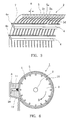
- a rotary drum type device 1 for separating solid particles from a liquid has a screen drum 2 fixed to a rotary shaft 3.
- the rotary shaft 3 is connected to a known drive mechanism (not shown) which can drive and rotate the screen drum 2.
- the rotary screen drum 2 has, as will be clear from Fig. 3, support rods 4 extending in the axial direction of the screen drum 2 and arranged generally cylindrically with a predetermined interval and having a projecting portion 4a in a radially outward end portion and a wedge wire 5 wound spirally on the outer periphery of the support rods 4 in substantially crossing direction to the support rods 4.
- the wedge wire 5 is arranged with its one side 5a facing outside and two other sides 5b and 5c forming a slit 6 which widens radially inwardly between adjacent wedge wire portions and with an inward apex 5d of said wedge wire 5 being welded to the projecting portion 4a of the support rods 4 at crossing points 7 of the wedge wire 5 and the support rods 4.
- the ends of the screen drum 2 are closed by seal plates 2a.
- a box type container 8 for temporarily storing a liquid 11 to be treated having a high water content rate such as sludge and supplying this liquid 11 to the screen drum 2 is provided outside of the screen drum 2, extending in parallel to the screen drum 2.
- the container 8 communicates with a tank 10 storing the liquid 11 to be treated via a tube 9 and receives the liquid 11 from the tank 10.
- the container 8 has an opening on the side facing the screen drum 2 so that the liquid 11 will be deposited on the outer periphery of the screen drum 2 and carried out of the container 8 as the screen drum 2 is rotated.
- a bottom plate 12 of the container 8 has an inclined opening end which is in contact with the outer periphery of the screen drum 2. This inclined opening end functions as a scraper means for stripping off cake deposited on the periphery of the screen drum 2.
- the inside space of the hollow screen drum 2 is connected to a known suction generator 13 such as a vacuum pump. By operating this suction generator 13, the pressure inside of the screen drum is reduced.
- the screen drum 2 has also a liquid takeout tube 14 for taking out a liquid content collected from the liquid 11 by suction.
- the width of the slit 6 of the wedge wire 5 of the screen drum 2 is set at a suitable value within a range between 1 micron to 150 microns having regard to the type and nature of the liquid to be treated, the purpose of treatment etc.
- the liquid 11 to be treated is supplied from the tank 10 to the container 8 and the screen drum 2 is rotated in the direction of arrow B while the suction generator 13 is operated.
- the liquid 11 to be treated is deposited on the screen surface consisting of the wedge wire 5 of the rotating screen drum 2 and carried out of the container 8. Since the inside of the screen drum 2 is reduced in pressure by the operation of the suction generator 13 and, therefore, a majority of the liquid content of the liquid 11 to be treated is sucked into the inside of the screen drum 2 through the slit 6 and taken out of the screen drum 2 through the liquid takeout tube 14.
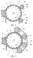
- Fig. 4 shows another embodiment of the invention.
- the same component parts as the embodiment of Figs. 1 to 3 are designated by the same reference characters and detailed description thereof will be omitted.
- two rolls 20 are disposed in parallel to the screen drum 2. These rolls 20 are made by bonding a rubber sheet 20b about an iron core 20a.
- the gap between the rolls 20 and the outer periphery of the screen drum 2 is set at a value which is slightly smaller than the thickness of the cake 15 formed on the screen drum 2.
- Fig. 5 shows another embodiment of the invention.
- four guide rolls 22 which are disposed in parallel to the screen drum 2 with a predetermined interval between the outer periphery of the guide rolls 22 and outer periphery of the screen drum 2.
- An endless belt 23 is provided along the guide rolls 22 for covering the cake 15 produced on the outer periphery of the screen drum 2.
- the endless belt 23 comes into abutting contact with the cake 15 formed on the outer periphery of the screen drum 2 and thereby is driven.
- the guide rolls 22 are driven and rotated in the direction of arrow D. Since the endless belt 23 covers the cake 15 from the outside, the cake 15 is sealed from the outside air and this contributes to increase in the suction force acting in the screen drum 2 and thereby enhances dehydration of the cake.
- Figs. 6 to 10 show another embodiment of the invention which include blocking prevention means and various blocking prevention means used in this embodiment.
- the basic structure of this embodiment is the same as the embodiment of Figs. 1 to 3.
- a wire brush 26 extending in the axial direction of the screen drum 2 is provided in the container 8.
- the wire brush 26 may be replaced by a scraper plate 28 provided in contact with the outer periphery of the screen drum 2 and extending in the axial direction of the screen drum 2.
- a nozzle tube 31 having a line of fluid injecting nozzles 30 may be provided in close proximity either to the inside or outside of the screen drum 2 and extending in the axial direction of the screen drum 2 and the nozzle tube 31 may be connected to a fluid supply source (not shown) for injecting fluid such as air or water from the nozzles 30 onto the screen drum 2 and thereby rinsing the screen drum 2.
- a known electrically or pneumatically operated vibrator 33 may be provided on the seal plate 2a of the screen drum 2 in addition to the basic structure of the embodiment of Figs. 1 to 3 so as to impart vibration regularly to the screen drum 2 and thereby remove blocking of the slit 6.
- the slit 6 of the wedge wire 5 may be set at a relatively large value below 150 microns (e.g., 100 microns to 150 microns) and a filter layer 35 may be formed on the outer periphery of the screen drum 2 by providing a filter material such as diatom earth. Separation of solid particles from a liquid can be achieved mainly by this filter layer 35.
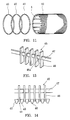
- Figs. 11 to 14 show another embodiment of the invention.
- the device for separating solid particles from a liquid has substantially the same basic structure as the embodiment shown in Fig. 6 except that, in the embodiment of Fig. 6, the wedge wire 5 is wound spirally on the cylindrically arranged support rods 4 whereas in the present embodiment, the wedge wire is constructed of a plurality of parallel rings which are wound annularly on the support rods 4. Slits 41 are formed between respective rings 40 and the width of the slits 41 is set within a range between 1 micron to 150 microns in the same manner as in the embodiment of Fig. 6.
- a wedge wire 42 is spirally wound on the cylindrically arranged support rods 4 as shown in Fig. 12A. Then, this spiral wedge wire 42 is cut into upper portions (1), (2), (3), (4), (5) and (6) and lower portions (a), (b), (c), (d), (e) and (f) along line P in Fig. 12A. Then, either the upper portion or lower portion of the cut wedge wire 42 is pulled horizontally to shift one pitch and the upper portion (2) is welded to the lower portion (a), the upper portion (3) to the lower portion (b), the upper portion (4) to the lower portion (c), the upper portion (5) to the lower portion (d) and the upper portion (6) to the lower portion (e) respectively as shown in Fig. 12B.
- a filler as shown in Fig. 13 is provided.
- the filler 45 has thin plate-like filler plates 46 each being provided in correspondence to each slit 41 of the wedge wire rings 40 and a holder rod 47 which is inserted in holder rod insertion apertures 46a formed in the upper portion of the filler plates 46 to fixedly hold the filler plates 46.
- the filler 45 is provided in the axial direction of the screen drum 2 in the container 8 in such a manner that the filler plates 46 are inserted in the slits 41.
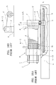
- a method for manufacturing a rotary drum screen used in the rotary drum type device for separating solid particles from a liquid according to the invention will be described.
- a screen drum manufacturing apparatus 50 has a front bed 52 and a rear bed 54.
- a screw 64 is rotatably supported by bearings 60 and 62 which are mounted on support frames 56 and 58 provided on the front and rear beds 52 and 54.
- the screw 64 has a threaded front portion 64b of a large diameter, a central step portion 64a and an unthreaded rear portion 64c of a reduced diameter.
- Rails 66 are laid on the front bed 52 below the screw 64.
- a cylindrical screw cover 68 has a threaded inner periphery and is disposed coaxially with the screw 64 in threaded engagement with the screw 64.
- Wheels 70 are fixed to the front end portion of the screw cover 68 in such a manner that the wheels 70 can run along the rails 66. Thus, the screw cover 68 slides along the screw 64 as the latter is rotated.
- An annular front support rod holder 74 is supported rotatably and not movably in the axial direction in the vicinity of a foreward end of the screw cover 68.
- An annular rear support rod holder 76 having a central opening 76b is supported rotatably and not movably in the axial direction on the reduced diameter portion 64c of the screw 64.
- a drive unit 78 for driving and rotating the front support rod holder 74 is connected to the front support rod holder 74.
- the drive unit 78 can rotate the front support rod holder 74 with a rotation speed necessary for realizing a desired width of the wedge wire slit.
- the rear support rod holder 76 is driven by the rotation of the front support rod holder 74.
- the rear support rod holder 76 has a smaller diameter than the central opening 67a formed in the welder support table 67 and can slide in the central opening 67a. Since the diameter of the large diameter portion 64b is larger than the diameter of the central opening 76b of the rear support rod holder 76, the movement of the rear support rod holder 76 in the advancing direction is prevented by abutting engagement of a front surface 76a of the holder 76 with the step portion 64b of the screw 64. The rear support rod holder 76 is rotated by rotation of the front support rod holder 74.
- a wedge wire supply drum 80 storing wedge wire is disposed behind the welder support table 67.
- a disk-like pressure roll 82 which is disposed in parallel to the screw cover at a predetermined interval from the outer periphery of the screw cover 68 for pressing the wedge wire wound on the support rods to the support rods. The pressure roll 82 is rotated as the screen drum 2 is rotated.
- a wedge wire holder 84 is provided at a location immediately before the wedge wire is wound on the support rods.
- This wedge wire holder 84 consists of holder portions 84a and 84b for enabling the wedge wire to pass through them as shown in Figs. 16A and 16B. After passing the wedge wire, these holder portions 84a and 84b are fixed together by means of bolts 85 and nuts 86.
- the wedge wire holder 84 has a wedge wire insertion opening 84b having a size slightly larger than the cross section of the wedge wire and has a configuration similar to the cross section of the wedge wire and has a foremost end portion 84c having a configuration similar to a bird's bill.
- the holder 84 is fixed to a rod 90 by means of a bolt 92 and this rod 90 is pivotably mounted on a frame 96 pivotaby in the vertical directon and unmovably in the horizontal direction.
- a laser welder 100 of a known construction is disposed at a location immediately after the wedge wire is wound on the support rods.
- Manufacturing of the screen drum is performed in the following steps:
Landscapes
- Chemical & Material Sciences (AREA)
- Chemical Kinetics & Catalysis (AREA)
- Engineering & Computer Science (AREA)
- Mechanical Engineering (AREA)
- Filtration Of Liquid (AREA)
Applications Claiming Priority (2)
| Application Number | Priority Date | Filing Date | Title |
|---|---|---|---|
| US08/427,089 US5618424A (en) | 1995-04-21 | 1995-04-21 | Rotary drum type device for separating solid particles from a liquid |
| US427089 | 1995-04-21 |
Publications (3)
| Publication Number | Publication Date |
|---|---|
| EP0738531A2 true EP0738531A2 (de) | 1996-10-23 |
| EP0738531A3 EP0738531A3 (de) | 1996-12-18 |
| EP0738531B1 EP0738531B1 (de) | 2000-01-05 |
Family
ID=23693450
Family Applications (1)
| Application Number | Title | Priority Date | Filing Date |
|---|---|---|---|
| EP96105807A Expired - Lifetime EP0738531B1 (de) | 1995-04-21 | 1996-04-12 | Drehtrommelvorrichtung zum Trennen von Feststoffpartikeln aus einer Flüssigkeit und Herstellungsverfahren und Vorrichtung hierfür |
Country Status (3)
| Country | Link |
|---|---|
| US (2) | US5618424A (de) |
| EP (1) | EP0738531B1 (de) |
| DE (1) | DE69605965T2 (de) |
Cited By (11)
| Publication number | Priority date | Publication date | Assignee | Title |
|---|---|---|---|---|
| WO1999013959A1 (en) * | 1997-09-17 | 1999-03-25 | Idracos S.P.A. | An apparatus for screening and compacting |
| WO2000015901A1 (de) * | 1998-09-14 | 2000-03-23 | Heinrich Fiedler Gmbh & Co. Kg | Siebvorrichtung |
| WO2002028907A1 (en) * | 2000-10-06 | 2002-04-11 | Coöperatieve Verkoop- En Productievereniging Van Aardappelmeel En Derivaten Avebe B.A. | Washing and dewatering of suspensions |
| EP1268034A4 (de) * | 2000-01-26 | 2004-04-14 | Douglas L Woerner | Rotierender trommelfilter |
| WO2005061851A1 (en) * | 2003-12-11 | 2005-07-07 | Halliburton Energy Services, Inc. | System and method of constructing wire wrap well screens |
| CN110523611A (zh) * | 2019-08-28 | 2019-12-03 | 马鞍山采石矶涂料有限公司 | 一种陶瓷高分子微粒组成的绿色涂料生产用筛分装置 |
| CN111135625A (zh) * | 2020-01-16 | 2020-05-12 | 梁红雨 | 一种养殖业排出污水的处理方法 |
| CN111570288A (zh) * | 2020-05-25 | 2020-08-25 | 李静静 | 一种自动清洁式饲料筛选装置及使用方法 |
| CN114939527A (zh) * | 2022-07-26 | 2022-08-26 | 烟台环山饲料有限公司 | 一种可除去饲料粉渣的饲料灌装装置 |
| CN115155141A (zh) * | 2022-08-25 | 2022-10-11 | 新疆碧水源环境资源股份有限公司 | 新型污水预处理过滤装置 |
| CN117920563A (zh) * | 2024-03-21 | 2024-04-26 | 泸州东方农化有限公司 | 一种除草剂生产筛分装置及筛分方法 |
Families Citing this family (62)
| Publication number | Priority date | Publication date | Assignee | Title |
|---|---|---|---|---|
| US5718826A (en) * | 1995-05-26 | 1998-02-17 | Cae Screen Plates, Inc. | Screen and method of manufacture |
| US5954956A (en) * | 1997-07-22 | 1999-09-21 | J&L Fiber Services | Modular screen cylinder and a method for its manufacture |
| US6070739A (en) * | 1998-01-23 | 2000-06-06 | Nagaoka; Tadayoshi | Filtering device |
| US5954960A (en) * | 1998-03-19 | 1999-09-21 | Nagaoka Usa Corporation | Rotary drum type dehydrator |
| US6138838A (en) * | 1998-05-29 | 2000-10-31 | J&L Fiber Services, Inc. | Screen media and a screening passage therefore |
| US6063298A (en) | 1998-07-09 | 2000-05-16 | Baker Hughes Incorporated | Filtering centrifuge with cake heel removal mechanism and associated method |
| WO2000020091A1 (en) * | 1998-10-06 | 2000-04-13 | Thermo Black Clawson Inc. | Improved wedge wire and paper stock screening apparatus incorporating such wedge wire |
| US6488842B2 (en) * | 1999-02-26 | 2002-12-03 | Tadayoshi Nagaoka | Filtering device |
| JP4545880B2 (ja) * | 2000-05-16 | 2010-09-15 | 株式会社泉精器製作所 | 固液分離装置 |
| US6460757B1 (en) | 2000-11-14 | 2002-10-08 | Newscreen As | Apparatus and method for forming slotted wire screens |
| US20060162747A1 (en) * | 2005-01-25 | 2006-07-27 | Mike Belleville | Polypro scrap accumulator |
| JP2006263707A (ja) * | 2005-02-23 | 2006-10-05 | Bussan Nanotech Research Institute Inc | ガス濾過装置 |
| CA2509966A1 (en) * | 2005-06-01 | 2006-12-01 | Accent Manufacturing, Inc. | Internally fed rotary screen manure separator |
| US7981282B2 (en) * | 2006-04-25 | 2011-07-19 | Tm Industrial Supply, Inc. | Automatic slurry strainer |
| KR100793558B1 (ko) * | 2006-09-18 | 2008-01-14 | 삼성에스디아이 주식회사 | 유기전계발광 표시장치 및 그의 모기판과 유기전계발광표시장치의 제조방법 |
| US20090211965A1 (en) * | 2008-02-21 | 2009-08-27 | Weatherford/Lamb, Inc. | Arrangement for splicing panels together to form a cylindrical screen |
| US8303826B2 (en) * | 2008-09-05 | 2012-11-06 | Tm Industrial Supply, Inc. | Automatic slurry strainer |
| US8317034B2 (en) * | 2008-11-13 | 2012-11-27 | John Patrick Fetrow | Separation of particulate matter and animal manure |
| US8728801B2 (en) * | 2009-01-21 | 2014-05-20 | Daritech, Inc. | Composter mechanism |
| US8608955B2 (en) * | 2009-03-25 | 2013-12-17 | Tm Industrial Supply, Inc. | Automatic slurry strainer |
| CA2678839A1 (fr) | 2009-09-14 | 2011-03-14 | Gea Houle Inc. | Separateur a grille horizontale rotative |
| US8776808B2 (en) * | 2009-09-17 | 2014-07-15 | Whirlpool Corporation | Rotary drum filter for a dishwashing machine |
| US9918609B2 (en) * | 2009-12-21 | 2018-03-20 | Whirlpool Corporation | Rotating drum filter for a dishwashing machine |
| US8667974B2 (en) | 2009-12-21 | 2014-03-11 | Whirlpool Corporation | Rotating filter for a dishwashing machine |
| US9119515B2 (en) | 2010-12-03 | 2015-09-01 | Whirlpool Corporation | Dishwasher with unitary wash module |
| US8627832B2 (en) | 2010-12-13 | 2014-01-14 | Whirlpool Corporation | Rotating filter for a dishwashing machine |
| US9687135B2 (en) | 2009-12-21 | 2017-06-27 | Whirlpool Corporation | Automatic dishwasher with pump assembly |
| US8746261B2 (en) | 2009-12-21 | 2014-06-10 | Whirlpool Corporation | Rotating drum filter for a dishwashing machine |
| DE202010001849U1 (de) | 2010-01-30 | 2010-05-20 | Nordischer Maschinenbau Rud. Baader Gmbh + Co. Kg | Vorrichtung zum Trennen von miteinander vermischten Stoffen unterschiedlicher Fließfähigkeit |
| US9668636B2 (en) | 2010-11-16 | 2017-06-06 | Whirlpool Corporation | Method and apparatus for dishwasher with common heating element for multiple treating chambers |
| US9113766B2 (en) | 2010-11-16 | 2015-08-25 | Whirlpool Corporation | Method and apparatus for dishwasher with common heating element for multiple treating chambers |
| US9034112B2 (en) | 2010-12-03 | 2015-05-19 | Whirlpool Corporation | Dishwasher with shared heater |
| US9023456B2 (en) | 2011-03-18 | 2015-05-05 | Bilfinger Water Technologies, Inc. | Profiled wire screen for process flow and other applications |
| US8733376B2 (en) | 2011-05-16 | 2014-05-27 | Whirlpool Corporation | Dishwasher with filter assembly |
| US9107559B2 (en) | 2011-05-16 | 2015-08-18 | Whirlpool Corporation | Dishwasher with filter assembly |
| US9010344B2 (en) | 2011-06-20 | 2015-04-21 | Whirlpool Corporation | Rotating filter for a dishwashing machine |
| US9005369B2 (en) | 2011-06-20 | 2015-04-14 | Whirlpool Corporation | Filter assembly for a dishwasher |
| US9265401B2 (en) | 2011-06-20 | 2016-02-23 | Whirlpool Corporation | Rotating filter for a dishwashing machine |
| US20120318296A1 (en) | 2011-06-20 | 2012-12-20 | Whirlpool Corporation | Ultra micron filter for a dishwasher |
| US9861251B2 (en) | 2011-06-20 | 2018-01-09 | Whirlpool Corporation | Filter with artificial boundary for a dishwashing machine |
| US9751787B1 (en) | 2011-08-23 | 2017-09-05 | Daritech, Inc. | Anaerobic digesting systems and methods for processing animal waste |
| US9301667B2 (en) | 2012-02-27 | 2016-04-05 | Whirlpool Corporation | Soil chopping system for a dishwasher |
| US9237836B2 (en) | 2012-05-30 | 2016-01-19 | Whirlpool Corporation | Rotating filter for a dishwasher |
| US9730570B2 (en) | 2012-05-30 | 2017-08-15 | Whirlpool Corporation | Reduced sound with a rotating filter for a dishwasher |
| US9451862B2 (en) | 2012-06-01 | 2016-09-27 | Whirlpool Corporation | Dishwasher with unitary wash module |
| US9532700B2 (en) | 2012-06-01 | 2017-01-03 | Whirlpool Corporation | Dishwasher with overflow conduit |
| US9833120B2 (en) | 2012-06-01 | 2017-12-05 | Whirlpool Corporation | Heating air for drying dishes in a dishwasher using an in-line wash liquid heater |
| US9554688B2 (en) | 2012-10-23 | 2017-01-31 | Whirlpool Corporation | Rotating filter for a dishwasher and methods of cleaning a rotating filter |
| KR101516810B1 (ko) * | 2014-08-08 | 2015-05-04 | 주식회사 신우엔지니어링 | 원뿔형 드럼스크린 제조장치 및 제조방법 |
| CA2963406A1 (en) | 2016-04-05 | 2017-10-05 | Daritech, Inc. | Self-flushing anaerobic digester system |
| KR101648738B1 (ko) * | 2016-05-09 | 2016-08-17 | 주식회사 윌스크린 | 스크린 및 이를 구비한 스크리닝 장치 |
| EP3609596A4 (de) * | 2017-04-13 | 2021-01-06 | Aqseptence Group, Inc. | Siebfilter für mikrofiltration |
| CN107413099A (zh) * | 2017-06-08 | 2017-12-01 | 陈水华 | 一种振动分离装置 |
| CN108579173A (zh) * | 2018-02-28 | 2018-09-28 | 铜陵市业强环保设备有限责任公司 | 一种用于链板带式真空过滤机的螺旋滚轮式刮刀卸料装置 |
| PL245339B1 (pl) * | 2019-04-01 | 2024-07-01 | Marek Mania | Rura szczelinowa spiralna do filtrów samooczyszczających się, ciśnieniowych oraz filtr szczelinowy samooczyszczający się ciśnieniowy z taką rurą szczelinową |
| KR102150410B1 (ko) * | 2020-04-20 | 2020-09-01 | 이준호 | 선별공의 막힘을 해소하는 골재의 토분 선별 장치 및 방법 |
| CN112774783A (zh) * | 2020-12-25 | 2021-05-11 | 吴后梅 | 一种用于中药加工的往复式研磨装置 |
| CN112791928A (zh) * | 2021-01-20 | 2021-05-14 | 王长桂 | 一种建筑用沙子过滤装置 |
| CN113617631A (zh) * | 2021-08-26 | 2021-11-09 | 安庆五谷香食品有限公司 | 一种用于烘焙食品的分拣装置 |
| WO2025065052A1 (en) * | 2023-09-25 | 2025-04-03 | The University Of Melbourne | An apparatus for dewatering a suspension |
| CN119771750A (zh) * | 2024-12-03 | 2025-04-08 | 三峡大学 | 一种岩土筛分机 |
| CN119909447B (zh) * | 2025-04-03 | 2025-07-15 | 广东铨冠智能科技有限公司 | 一种螺旋导流旋转空心筒切屑液过滤设备 |
Citations (1)
| Publication number | Priority date | Publication date | Assignee | Title |
|---|---|---|---|---|
| US4407720A (en) | 1982-04-08 | 1983-10-04 | Bratten Jack R | Method and apparatus for filtration of contaminated liquids |
Family Cites Families (16)
| Publication number | Priority date | Publication date | Assignee | Title |
|---|---|---|---|---|
| GB199853A (en) * | 1922-04-10 | 1923-07-05 | Hermann Plauson | Improvements in rotary filters |
| BE638824A (de) * | 1963-10-08 | |||
| US3962091A (en) * | 1973-01-04 | 1976-06-08 | Dorr-Oliver Incorporated | Rotary drum filter with wire deck, apparatus and method |
| US3875977A (en) * | 1973-03-23 | 1975-04-08 | Universal Oil Prod Co | Method for making cylindrical screens |
| NZ182084A (en) * | 1976-09-17 | 1981-02-11 | Contra Shear Holdings | Rotating drum screen |
| US4155693A (en) * | 1978-07-24 | 1979-05-22 | Ethyl Corporation | Embossed screen assembly |
| DE3342689C2 (de) * | 1983-11-25 | 1987-03-05 | Jürgen 7085 Bopfingen Stolch | Filtervorrichtung zum Entfernen von Verunreinigungen aus Flüssigkeiten, insbesondere aus Dispersionsfarben |
| US5000850A (en) * | 1986-09-10 | 1991-03-19 | Engelhard Corporation | Apparatus for dewatering an aqueous clay suspension |
| US4737277A (en) * | 1986-11-03 | 1988-04-12 | Dorr-Oliver Incorporated | Vacuum expression belt tracking and control apparatus for rotary drum vacuum filter |
| DE3706352A1 (de) * | 1987-02-27 | 1988-09-08 | Juergen Stolch | Verfahren und vorrichtung zum passieren von marmelade |
| FI82388C (fi) * | 1989-06-29 | 1991-03-11 | Outokumpu Oy | Foerfarande foer rening av filterplattorna i en sugtorkningsanordning. |
| US5064536A (en) * | 1989-07-03 | 1991-11-12 | Bratten Jack R | Wedgewire filter and method of manufacture |
| DE9005503U1 (de) * | 1990-05-15 | 1990-07-19 | Dia Pumpenfabrik Hammelrath & Schwenzer GmbH & Co. KG, 4000 Düsseldorf | Vorrichtung zum Trennen von Feststoffen aus einer Flüssigkeit |
| DE4016915A1 (de) * | 1990-05-25 | 1991-11-28 | Nordenskjoeld Reinhart Von | Verfahren und vorrichtung zur mechanischen abscheidung von feststoffen aus einem fluid |
| US5158691A (en) * | 1990-08-30 | 1992-10-27 | Henry Filters, Inc. | Filter apparatus and method for filtering contaminants from machine tool coolant |
| US5281343A (en) * | 1993-04-20 | 1994-01-25 | Ingersoll-Rand Company | Vacuum filtration system and method of filtering pulp fibers from pulp slurry using the same |
-
1995
- 1995-04-21 US US08/427,089 patent/US5618424A/en not_active Expired - Fee Related
-
1996
- 1996-04-09 US US08/629,536 patent/US5622625A/en not_active Expired - Fee Related
- 1996-04-12 DE DE69605965T patent/DE69605965T2/de not_active Expired - Fee Related
- 1996-04-12 EP EP96105807A patent/EP0738531B1/de not_active Expired - Lifetime
Patent Citations (1)
| Publication number | Priority date | Publication date | Assignee | Title |
|---|---|---|---|---|
| US4407720A (en) | 1982-04-08 | 1983-10-04 | Bratten Jack R | Method and apparatus for filtration of contaminated liquids |
Cited By (14)
| Publication number | Priority date | Publication date | Assignee | Title |
|---|---|---|---|---|
| WO1999013959A1 (en) * | 1997-09-17 | 1999-03-25 | Idracos S.P.A. | An apparatus for screening and compacting |
| WO2000015901A1 (de) * | 1998-09-14 | 2000-03-23 | Heinrich Fiedler Gmbh & Co. Kg | Siebvorrichtung |
| US6579458B2 (en) | 1998-09-14 | 2003-06-17 | Heinrich Fiedler Gmbh & Co. Kg | Screening device |
| EP1268034A4 (de) * | 2000-01-26 | 2004-04-14 | Douglas L Woerner | Rotierender trommelfilter |
| WO2002028907A1 (en) * | 2000-10-06 | 2002-04-11 | Coöperatieve Verkoop- En Productievereniging Van Aardappelmeel En Derivaten Avebe B.A. | Washing and dewatering of suspensions |
| WO2005061851A1 (en) * | 2003-12-11 | 2005-07-07 | Halliburton Energy Services, Inc. | System and method of constructing wire wrap well screens |
| CN110523611A (zh) * | 2019-08-28 | 2019-12-03 | 马鞍山采石矶涂料有限公司 | 一种陶瓷高分子微粒组成的绿色涂料生产用筛分装置 |
| CN111135625A (zh) * | 2020-01-16 | 2020-05-12 | 梁红雨 | 一种养殖业排出污水的处理方法 |
| CN111570288A (zh) * | 2020-05-25 | 2020-08-25 | 李静静 | 一种自动清洁式饲料筛选装置及使用方法 |
| CN114939527A (zh) * | 2022-07-26 | 2022-08-26 | 烟台环山饲料有限公司 | 一种可除去饲料粉渣的饲料灌装装置 |
| CN114939527B (zh) * | 2022-07-26 | 2022-11-11 | 烟台环山饲料有限公司 | 一种可除去饲料粉渣的饲料灌装装置 |
| CN115155141A (zh) * | 2022-08-25 | 2022-10-11 | 新疆碧水源环境资源股份有限公司 | 新型污水预处理过滤装置 |
| CN117920563A (zh) * | 2024-03-21 | 2024-04-26 | 泸州东方农化有限公司 | 一种除草剂生产筛分装置及筛分方法 |
| CN117920563B (zh) * | 2024-03-21 | 2024-06-04 | 泸州东方农化有限公司 | 一种除草剂生产筛分装置及筛分方法 |
Also Published As
| Publication number | Publication date |
|---|---|
| EP0738531A3 (de) | 1996-12-18 |
| US5622625A (en) | 1997-04-22 |
| US5618424A (en) | 1997-04-08 |
| EP0738531B1 (de) | 2000-01-05 |
| DE69605965D1 (de) | 2000-02-10 |
| DE69605965T2 (de) | 2000-08-17 |
Similar Documents
| Publication | Publication Date | Title |
|---|---|---|
| US5622625A (en) | Method of manufacturing a drum | |
| JP4308759B2 (ja) | 材料混合物の継続濾過装置 | |
| DE1510381C3 (de) | Vorrichtung zur Abscheidung von aus Spinnereimaschinen, insbesondere Karden, abgesaugtem Faserflug | |
| EP0454045B1 (de) | Zentrifugen-Trockner | |
| DE60002690T2 (de) | Methode und apparat zur herstellung schmelzgeblasener filterkartuschen mit schmelzgeblasenen kernen und daraus hergestellte filterkartuschen | |
| DE2511195C3 (de) | Verfahren zum Filtrieren und Filter zur Durchführung des Verfahrens | |
| US6070739A (en) | Filtering device | |
| EP0044566B1 (de) | Vorrichtung und Verfahren zum Abtrennen suspendierter Feststoffe aus einem strömenden Medium | |
| DE69217570T2 (de) | Vorrichtung zum Sammeln und Entfernen von Flockenstaub an eine Strickmaschine | |
| EP0086770B1 (de) | Filtervorrichtung, insbesondere für Getränke | |
| EP2185262B1 (de) | Druckfilter mit vibrationsantrieb | |
| DE3523998C2 (de) | ||
| DE3500556C2 (de) | Zentrifuge | |
| EP0566908A2 (de) | Flüssigkeitsfilter | |
| DE69323887T2 (de) | Filtriervorrichtung | |
| DE19916539A1 (de) | Reinigungsvorrichtung für viskose Materialien | |
| DE4117682A1 (de) | Vorrichtung zum filtrieren einer verunreinigten loesung und einer bearbeitungsfluessigkeit bei einer werkstueckbearbeitungsmaschine | |
| JP2801778B2 (ja) | 繊維懸濁液の分離方法とその装置 | |
| DE69014621T2 (de) | Kontinuierlich arbeitende filterzentrifuge. | |
| DE2651099C2 (de) | Vertikale Schwingzentrifuge | |
| EP1772176B1 (de) | Vorrichtung zum Trennen von Feststoffen aus flüssigen Medien | |
| JPS584119B2 (ja) | 故紙を選別するための方法 | |
| JPH0924216A (ja) | 濾過装置 | |
| DE3026923C2 (de) | Vorrichtung zum Behandeln von Filtermaterial | |
| EP0438092A1 (de) | Vorrichtung zum Eindicken von Fasersuspension |
Legal Events
| Date | Code | Title | Description |
|---|---|---|---|
| PUAI | Public reference made under article 153(3) epc to a published international application that has entered the european phase |
Free format text: ORIGINAL CODE: 0009012 |
|
| AK | Designated contracting states |
Kind code of ref document: A2 Designated state(s): DE FR GB |
|
| PUAL | Search report despatched |
Free format text: ORIGINAL CODE: 0009013 |
|
| AK | Designated contracting states |
Kind code of ref document: A3 Designated state(s): DE FR GB |
|
| 17P | Request for examination filed |
Effective date: 19970310 |
|
| 17Q | First examination report despatched |
Effective date: 19970627 |
|
| GRAG | Despatch of communication of intention to grant |
Free format text: ORIGINAL CODE: EPIDOS AGRA |
|
| GRAG | Despatch of communication of intention to grant |
Free format text: ORIGINAL CODE: EPIDOS AGRA |
|
| GRAH | Despatch of communication of intention to grant a patent |
Free format text: ORIGINAL CODE: EPIDOS IGRA |
|
| GRAH | Despatch of communication of intention to grant a patent |
Free format text: ORIGINAL CODE: EPIDOS IGRA |
|
| GRAA | (expected) grant |
Free format text: ORIGINAL CODE: 0009210 |
|
| AK | Designated contracting states |
Kind code of ref document: B1 Designated state(s): DE FR GB |
|
| REF | Corresponds to: |
Ref document number: 69605965 Country of ref document: DE Date of ref document: 20000210 |
|
| ET | Fr: translation filed | ||
| PLBE | No opposition filed within time limit |
Free format text: ORIGINAL CODE: 0009261 |
|
| STAA | Information on the status of an ep patent application or granted ep patent |
Free format text: STATUS: NO OPPOSITION FILED WITHIN TIME LIMIT |
|
| 26N | No opposition filed | ||
| REG | Reference to a national code |
Ref country code: GB Ref legal event code: IF02 |
|
| PGFP | Annual fee paid to national office [announced via postgrant information from national office to epo] |
Ref country code: GB Payment date: 20030409 Year of fee payment: 8 |
|
| PGFP | Annual fee paid to national office [announced via postgrant information from national office to epo] |
Ref country code: FR Payment date: 20030425 Year of fee payment: 8 |
|
| PG25 | Lapsed in a contracting state [announced via postgrant information from national office to epo] |
Ref country code: GB Free format text: LAPSE BECAUSE OF NON-PAYMENT OF DUE FEES Effective date: 20040412 |
|
| PGFP | Annual fee paid to national office [announced via postgrant information from national office to epo] |
Ref country code: DE Payment date: 20040430 Year of fee payment: 9 |
|
| GBPC | Gb: european patent ceased through non-payment of renewal fee |
Effective date: 20040412 |
|
| PG25 | Lapsed in a contracting state [announced via postgrant information from national office to epo] |
Ref country code: FR Free format text: LAPSE BECAUSE OF NON-PAYMENT OF DUE FEES Effective date: 20041231 |
|
| REG | Reference to a national code |
Ref country code: FR Ref legal event code: ST |
|
| PG25 | Lapsed in a contracting state [announced via postgrant information from national office to epo] |
Ref country code: DE Free format text: LAPSE BECAUSE OF NON-PAYMENT OF DUE FEES Effective date: 20051101 |