EP0736699A2 - Dispositif d'ajustement angulaire - Google Patents
Dispositif d'ajustement angulaire Download PDFInfo
- Publication number
- EP0736699A2 EP0736699A2 EP96105499A EP96105499A EP0736699A2 EP 0736699 A2 EP0736699 A2 EP 0736699A2 EP 96105499 A EP96105499 A EP 96105499A EP 96105499 A EP96105499 A EP 96105499A EP 0736699 A2 EP0736699 A2 EP 0736699A2
- Authority
- EP
- European Patent Office
- Prior art keywords
- support element
- tube
- guide
- drive transmission
- transmission means
- Prior art date
- Legal status (The legal status is an assumption and is not a legal conclusion. Google has not performed a legal analysis and makes no representation as to the accuracy of the status listed.)
- Withdrawn
Links
- 230000005540 biological transmission Effects 0.000 claims abstract description 38
- 230000033001 locomotion Effects 0.000 claims abstract description 34
- 230000009021 linear effect Effects 0.000 claims abstract description 24
- 230000008093 supporting effect Effects 0.000 claims abstract description 8
- 229910000831 Steel Inorganic materials 0.000 claims description 12
- 239000010959 steel Substances 0.000 claims description 12
- 230000003578 releasing effect Effects 0.000 claims description 2
- 230000005611 electricity Effects 0.000 abstract 1
- 230000007246 mechanism Effects 0.000 description 51
- 230000008901 benefit Effects 0.000 description 7
- 230000000474 nursing effect Effects 0.000 description 7
- 238000006073 displacement reaction Methods 0.000 description 6
- 244000089486 Phragmites australis subsp australis Species 0.000 description 4
- 230000008878 coupling Effects 0.000 description 4
- 238000010168 coupling process Methods 0.000 description 4
- 238000005859 coupling reaction Methods 0.000 description 4
- XEEYBQQBJWHFJM-UHFFFAOYSA-N Iron Chemical compound [Fe] XEEYBQQBJWHFJM-UHFFFAOYSA-N 0.000 description 3
- 230000000903 blocking effect Effects 0.000 description 3
- 239000000463 material Substances 0.000 description 3
- 230000004224 protection Effects 0.000 description 3
- 230000009467 reduction Effects 0.000 description 3
- 125000006850 spacer group Chemical group 0.000 description 3
- 238000005299 abrasion Methods 0.000 description 2
- 230000008859 change Effects 0.000 description 2
- 230000006835 compression Effects 0.000 description 2
- 238000007906 compression Methods 0.000 description 2
- 238000013461 design Methods 0.000 description 2
- 238000003801 milling Methods 0.000 description 2
- 238000012986 modification Methods 0.000 description 2
- 230000036961 partial effect Effects 0.000 description 2
- 230000002829 reductive effect Effects 0.000 description 2
- 238000005096 rolling process Methods 0.000 description 2
- 230000009183 running Effects 0.000 description 2
- 238000013519 translation Methods 0.000 description 2
- 238000003466 welding Methods 0.000 description 2
- 101100116570 Caenorhabditis elegans cup-2 gene Proteins 0.000 description 1
- 101100116572 Drosophila melanogaster Der-1 gene Proteins 0.000 description 1
- 241000209035 Ilex Species 0.000 description 1
- OIRDTQYFTABQOQ-UHTZMRCNSA-N Vidarabine Chemical compound C1=NC=2C(N)=NC=NC=2N1[C@@H]1O[C@H](CO)[C@@H](O)[C@@H]1O OIRDTQYFTABQOQ-UHTZMRCNSA-N 0.000 description 1
- 238000013459 approach Methods 0.000 description 1
- 238000005452 bending Methods 0.000 description 1
- 238000010276 construction Methods 0.000 description 1
- 238000005520 cutting process Methods 0.000 description 1
- 230000000694 effects Effects 0.000 description 1
- 230000001965 increasing effect Effects 0.000 description 1
- 229910052742 iron Inorganic materials 0.000 description 1
- 238000004519 manufacturing process Methods 0.000 description 1
- 230000013011 mating Effects 0.000 description 1
- 238000003825 pressing Methods 0.000 description 1
- 230000004044 response Effects 0.000 description 1
- 230000000284 resting effect Effects 0.000 description 1
- 238000004904 shortening Methods 0.000 description 1
- 230000003068 static effect Effects 0.000 description 1
- 238000003860 storage Methods 0.000 description 1
- 230000007704 transition Effects 0.000 description 1
Images













Classifications
-
- A—HUMAN NECESSITIES
- A47—FURNITURE; DOMESTIC ARTICLES OR APPLIANCES; COFFEE MILLS; SPICE MILLS; SUCTION CLEANERS IN GENERAL
- A47C—CHAIRS; SOFAS; BEDS
- A47C20/00—Head-, foot- or like rests for beds, sofas or the like
- A47C20/04—Head-, foot- or like rests for beds, sofas or the like with adjustable inclination
Definitions
- the invention relates to a device for angular adjustment according to claim 1.
- angle adjustment mechanisms e.g. known for the backrest of a couch.
- simple angle adjustment mechanisms are usually designed in two stages (upright position, reclined position) or use complex hydraulics or mechanics to set a continuous angle of inclination.
- simple lockable adjustment mechanisms only adjustments that correspond to the predetermined latching options are usually possible.
- the invention is therefore based on the object of avoiding the disadvantages of the prior art and, in particular, of creating an angle adjustment mechanism, in particular for a hospital and nursing bed or an entrance system (turnstile), which is simple and quick to produce and handle (easy to solve) and lock), is robust, saves weight and space.
- An advantage of the invention is that the angle adjustment mechanism according to the invention, which is the most technically complex part in a hospital and nursing bed, is realized by a simple mechanism, which is particularly particularly safe since the entire mechanism is "hidden”.
- the adjustment mechanism according to the invention realizes several types of necessary adjustments, in particular also a linear height adjustment in a patient bed can be used, whereby the same parts can be used for the rotary and linear adjustment.
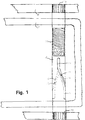
- FIG. 1 is a plan view of a first exemplary embodiment of an angle adjustment mechanism according to the invention for a backrest 7 'of a hospital and nursing bed (not shown), which in particular allows a drive via a crank or a similar manual actuating device, a motor or a rigidly lockable gas pressure spring, shown.
- the operation of the adjustment mechanism according to the invention results from the description of FIGS. 1 to 3.
- a crossbar 9 'of a hospital and nursing bed (not shown) is attached to the opposite legs of a carrier 4', which is part of the bed frame, not shown, by a connection.
- the axis 9 ' has a fine thread 70.
- the toothings 19 'and 29' only consist of two toothed rings, for fastening the axis 9 'to the head carrier 4'.
- the head frame part 7 ' is rotatably attached to the rod 9'.
- the axis 9 ' has two opposing curved longitudinal grooves or slots 71 and 72.
- the groove 71 is arranged on the side facing the fine thread 70 at the top of the axis 9 '. Starting from this side, the groove 71 runs straight, then curves like a screw, in order to then run again in a straight line in the longitudinal direction — offset by 90 degrees, in accordance with the desired angle adjustment range.
- the upper straight section of the groove 71 is denoted by 73, the curved section of the groove 71 by 74 and the lateral straight section of the groove 71 by 75.
- the groove 72 the upper straight section 73 being a lower straight section (not visible in FIG. 1), the curved section 74 being a curved section 76 (shown in dashed lines in FIG. 1) and the lateral straight section ( in FIG.
- section 75 corresponds to a lateral, straight section (shown in FIG. 1 pointing to the left in dashed lines).
- the grooves or slots (in the case that the axis 9 'is a tube) 71, 72 can also have a purely straight course, the slope of the slots, ie the angle to the longitudinal axis of the tube 9', determining the reduction.
- the length of the slot 71 and 72 together with the slope determine the angle adjustment range of the backrest 7 '.
- the head frame part 7 ' is preferably not U-shaped, but closed.
- the head frame part 7 ' is preferably bent out of a tube and the connection point is on the side, not shown in FIG. 1, opposite the axis 9'.
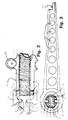
- FIG. 2 shows a schematic side or cross-sectional view of the shaft 9 'with the drive device 800, not shown in FIG. 1.
- the part of the axis 9 'in which the grooves 71, 72 are located is shown in cross section, while the rest of the figure is a side view.
- the device 800 consists of a lever 801 and a drive sleeve 802.
- the sleeve has a section 803 with an internal thread in order to cooperate with the fine thread 70 arranged on the outside of the shaft 9 ′.
- the sleeve is connected to a schematically illustrated worm gear 805, which is driven by a motor, not shown. The sleeve is rotated by the motor and the gear 805 and is shifted to the left along the rod 9 '.
- the lever 801 pushes the lever 801 along the path predetermined by the grooves 71 and 72, as a result of which the lever 801 is tilted vertically and adjusts the head frame part 7 ′ resting on it.
- the lever 801 engages in the grooves 71, 72 with two opposite pins 831, 832.
- the pins 831, 832 have needle or slide bearings 834, 835 to minimize the frictional resistance during the movement of the pins 831, 832 in the grooves 71 and 72, respectively, and to allow a lateral, in the rest position horizontal, pivoting movement of the lever, since the Lever 801 cannot be rigidly supported; the angle of the lever 801 to the axis 9 'changes continuously during the adjustment.
- the lever 801 also has pins 812, 813 provided with needle or slide bearings 810, 811, against which the drive part 802 can press in order to adjust the head frame part 7 '. This has the effect that the lever 801 can also move horizontally laterally during the displacement to the left and the associated horizontal displacement in order to support the head frame part 801 approximately in the middle during the adjustment. It should be noted that the grooves 71, 72, the course of which determines a translation, can also be adapted to the loads which change during the adjustment. This means that during the initial phase of the angle adjustment from the horizontal the greatest weight is effective and at the end of the angle adjustment, ie with the backrest upright, the weight is zero.
- the torsional stress on the axis 9 ' which depends on the diameter of the axis 9', the length of the lever 801 and the weight which acts on the lever 801, is minimized by the opposing position of the pins 831, 832.
- the bending stress of the axis 9 ' which is greatest when the axis 9' is in the upright position owing to the sharpest angle between the axis 9 'and the lever 801, is structurally optimized in that, in this position, the one to be carried by the lever and weight transmitted to the axis 9 'is smallest.
- FIG. 3 shows a side view of the lever or support element 801, preferably designed as a cast part, on which the head frame part 7 'rests.
- the lever has a recess 820 to allow the upper part of the head frame part to rest on the lever.
- the attachment of the lever 801 to the head frame part 7 ' is not rigid, due to the horizontal, lateral movement which the lever 801 undergoes during the vertical adjustment.
- cavities 821 are formed in the lever.
- the lever widens toward its portion 823.
- the section 823 has a circular cross section and a central opening 824 with an oval cross section, in which the rod 9 ′ shown in cross section with the opposite grooves 71, 72 is arranged.
- the two opposing cylindrical pins 831, 832 which are provided with needle or slide bearings 834, 835, engage in the grooves 71 and 72.
- the opening 824 is delimited by a section 837.
- Section 837 forms oval opening 824.
- Section 837 is formed by two pointed edges 838, 839, which can best be seen in the view in FIG. 2.
- the oval opening 824 provides the play necessary for the vertical adjustment of the lever.
- the rod 9 'shown in cross section has a cavity 9a, the height of which in cross section to Decreases towards the center and has sections 9b and 9c delimited by circular lines on the edge.
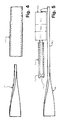
- Fig. 4 shows an alternative embodiment of an axis 9 "according to the invention.
- the reference numerals of Figs. 1-3 are used, however with a" “" as a suffix.
- the axis 9 " in particular over half a length, is designed as a steel strip rotated by 90 degrees.
- the drive sleeve 802" shown separately in the drawing acts to push the lever 801 "to be described in connection with FIG Function of the, described in connection with FIGS. 2 and 3, lever 801 ". Due to the twisting of the steel strip, a path or guide for the lever is also realized, as is the case with the grooves 71, 72 and correspondingly, which corresponds to the desired angle adjustment range.
- a drive device 846 consisting of a drive rod 842, a transmission 843, a motor 844 and an accumulator 845, is fastened on a non-rotated section 847 of the axis 9 ".
- the drive rod or adjusting spindle 842 has an attachment 848 which has a Recess or a mouth 849 in order to be able to drive or push the lever 801 (not shown) along its movement along the axis 9 ′′, in each of its angular positions.
- a rigidly lockable gas pressure spring can be used to move the lever 801.
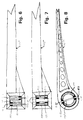
- FIG. 6-8 show various embodiments of levers or support arms which can slide along an axis of different design.
- a single-axis bearing is shown in FIG. 6, a double-axis bearing in FIG. 7 and a single-axis bearing in FIG. 8 using a hollow axis 9 ′′.
- FIG. 6 shows a lever 801 "which has an opening 850 which is rectangular, in particular square, in cross section.
- the twisted steel strip axis 9" already explained in connection with FIGS. 4 and 5 is shown hatched in cross section.
- two pins 851, 852 are inserted through two holes 853, 854 and attached to the lever 801 in a manner known in the art.
- Pins 851, 852 have needle or slide bearings 855, 856 so that lever 801 can slide along axis 9 "with minimal frictional resistance.
- bearings 855, 856 are only inside the opposite ends of pins 851, 852 the opening 850 and close to the bearing points of the pins in the lever 801 "to minimize the stress on the pins 851, 852.
- a lever 801 "' is shown in FIG. 7, which is generally similar to the lever 801" shown in FIG. 6. However, the lever 801 "'according to FIG. 7 is mounted on a hatched axis 9"', which is built up from two parallel (s) twisted steel strips 898, 899. A centrally inserted pin 870 with needle bearings 871 to reduce the friction connects the lever 801 "'to the axis 9"' '.
- a lever 801 "" is shown, which is guided on a hollow round rod or tube 9 "", into which not a groove is milled or on which a corresponding one- or two-sided limited (guide) path is placed, but which has two opposing continuous cutouts or slots 872, 872 ', the course of which corresponds to the grooves 71, 72 shown in FIG. 1. 7, a pin 870 'with needle bearings 871' is inserted transversely, which connects the lever 801 "" to the rod 9 "".
- FIG. 9 shows an axis 9 "", which corresponds to the axis 9 "” shown in FIG. 8.
- One already related Drive device 846 described with FIG. 5 is arranged in the axis 9 “” and rigidly attached to it, in particular by clamping.
- the spindle opening 849 advantageously engages in the pin 870 'shown in FIG. 8 in order to move the lever 801 along the hollow axis 9 "". Cables for the electrical supply of the drive device can also run in the axis 9 "”.
- the adjustment device according to the invention shown in the figures can also be used to adjust the height of the hospital bed.
- two of the axes explained above are preferably attached to a lower part.
- Two levers, also described above, face each other towards the center of the bed and are connected to one another.
- a linear displacement device simultaneously moves the two levers along the axes.
- the angle adjustment of the levers can be compensated via a joint, so that a pure translation or height adjustment is achieved.
- all known adjustment options for a bedside can be realized, i.e. in particular a total height adjustment, a height adjustment of a middle section of the lying surface, as well as an angle adjustment of a head and foot part of the lying surface, etc. See also FIGS. 31 and 32.
- the axle in contrast to the exemplary embodiments explained above, in which the axle is rigidly fastened in a rigid frame or on a movable, adjustable part, the axle can also be rotatably mounted.
- the lever or arm has no support function and can therefore degenerate into a pure system for a linear drive.
- the lever is then moved in a purely linear manner, ie in a plane along a straight line, and the adjustment element is driven via the rotating axis which is coupled to the adjustment element.
- the lever is then moved in grooves arranged on the axis or along a twisted one Strip steel guided, whereby the grooves (and thus the axis or the strip steel) are always rotated in the plane of movement of the lever with the axis during the movement of the lever.
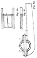
- FIGS. 10-12 and 13-16 show two further exemplary embodiments of the present invention.
- the drive is a motor or a gas pressure spring and is arranged in the rod (cf. FIG. 9).
- the lever in FIG. 12 is only arranged below the crossbar in order to provide space for a lying surface arranged on the crossbar.
- two roller bearings are arranged - separated by a spacer element - which roll along the opposite grooves during the displacement of the lever.
- the head section is shown in the horizontal position. It can be seen that the lever is at an angle to the frame. If the lever is moved along the grooves until the head part rises to the maximum, it is parallel to the frame. 11 is a side view of FIG. 10.
- the crossbar of the bed consists of two concentric tubes, the inner tube having two opposite oblique grooves (as already described above) and the outer tube having two straight grooves or vice versa.
- the bolt is not fastened to a lever and has two rolling bearings on each side of the spacer element, that is a total of four, which run in the four grooves.
- the outer tube rotates (see arrow in Fig. 13).
- the lying surface is attached directly to the outer tube and this becomes direct, without being undercut by a "lever" (cf. Fig. 14), adjusted.
- 15 is a side view of FIG. 14.
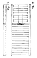
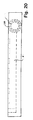
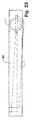
- FIGS. 17-24 in particular in FIGS. 21 and 24 shows a position with the backrest shifted from the rest position, specifically for the exemplary embodiments shown in FIGS. 13-16 and 10-12.
- FIG. 19 shows a variant of the invention.
- a backrest and a part of the support frame of a hospital bed are shown in FIG. 19.
- a concentric tube 330 bears around the crossbar 329, which is designed as a tube.
- the tube 329 has an obliquely arranged slot 371 therein, which can best be seen in FIG. 16.
- the outer tube 330 has a slot 381 running along the longitudinal axis.
- the inner tube 329 has a slot 372 opposite the slot 372 and arranged in a crossed manner.
- the outer tube 330 can also have a slot 382 opposite the slot 381, which is also arranged in the longitudinal direction.
- a bolt or pin 340 is arranged transversely in the tube arrangement formed from the tubes 329, 330 and is guided in the slots 371, 372, 381 and 382.
- four needle bearings are provided, which can best be seen in FIG. 13.
- the roller or needle bearings 343, 344 arranged at the ends of the pin 340 guide the pin 340 in the slots 381 and 382 of the outer tube 330.
- plain or roller bearings, here as needle bearings are designed to reduce friction when the bolt moves in the longitudinal direction.
- Movement of the pin 340 in the longitudinal direction produces a rotational movement of the outer tube 330, which is represented by an arrow in FIG. 13.
- the pin 340 can be moved linearly in the longitudinal direction via drive means, not shown, which have, for example, a gas pressure spring (not shown) arranged in the inner tube 329.
- drive means not shown
- the design of the slots of the inner tube 329 or of the outer tube 330 can also be reversed, ie the slots 371, 372 of the inner tube 329 rigidly fixed in the bed frame can be straight in the longitudinal direction, while the grooves 381, 382 of the outer tube 329 are arranged crossed in this case.
- the backrest 380 to be adjusted is firmly connected to the outer tube 330, for example by welding.
- a linear movement of a drive means is converted into a tilting movement of the backrest 380.
- the arrangement of the slots can also be reversed.
- the exemplary embodiment explained above is advantageous in that the bolt 340 is arranged completely in the tube arrangement 329, 330 and also has no parts protruding therefrom. This is particularly advantageous in order to ensure increased safety during use.
- the exemplary embodiment explained is different from the further exemplary embodiment of the present invention described below, which can be understood, for example, with reference to FIG. 12.
- the bolt must have outwardly projecting parts to allow attachment of the arm 350 which lifts the backrest as shown in FIG. 10, for example.
- the slots arranged on the outer tube can be crossed, in each case also crossed opposite to the adjacent slot of the inner tube.
- This has the particular advantage that the entire arrangement becomes more symmetrical about the longitudinal axis of the concentric tubes and that a portion or a component of the force that the bolt end exerts on the inner surfaces of the slots on the outer tube can assist the rotation of the outer tube instead (in the case of longitudinal slots on the outer tube) to ensure friction. In this case, therefore, the friction is smaller and the wear on the bearing or groove is also reduced.
- a pair of slots (one on the inner tube and the other on the outer tube) is sufficient for the adjustment mechanism according to the invention if the load is not too high.
- FIGS. 19 to 21 show a further modified embodiment of the present invention.
- This embodiment differs from the embodiment shown in FIGS. 19 to 21 in that, instead of the outer tube 330 shown in FIG. 21, for example, a lever or arm 350 is provided in order to transmit the drive to the backrest 380.
- a bolt 340 is guided in the slots 371, 372 as above.
- Needle bearings 341, 342 are arranged on the bolt 340 and, as above, separated by a spacer 351, which can best be seen in FIG. 12, at a distance which corresponds to the diameter of the tube 329.
- the pin 340 extends beyond the tube 329 on both sides to allow connection to an arm 350.
- the arrangement of the pin 340 in the tube 329 or the attachment of the arm 350 to the pin 340 can best be seen from the illustration in FIG. 12.
- the arm 350 corresponds to the lever or arm, as has already been explained in connection with FIG. 3 or FIGS. 6 to 8. By a longitudinal displacement of the pin 340, this is by the Guide rotated in the slots 371.372, and thus also the arm 350 rigidly connected to the pin 340.
- the arm 350 forms a supporting element for the backrest 380 to be adjusted.
- a continuous groove i.e. a longitudinal slot
- a longitudinal groove can be understood.
- Such a “groove” can be formed as a recess, for example by milling, in the tube, but also by at least one raised or excellent approach.
- the grooves 381, 382 of the outer tube 330 can be formed as guide grooves on the inside of the outer tube 330, as a result of which the entire adjustment mechanism is invisible to the outside and the tube is not weakened by a material recess.
- a drive mechanism for longitudinally displacing the guided bolt which is designed as an electric motor, has already been described in connection with FIG. 9.
- a locking or blocking mechanism will now be described in connection with FIG. 25.
- a rigidly lockable gas pressure spring is used as the drive means, this is not necessary.
- a Bowden cable is used to linearly adjust the pin 340, a locking mechanism is required.
- Such a locking mechanism is shown in Fig. 25, wherein in this figure the embodiment of the adjusting mechanism already described in connection with FIGS. 19 to 21 is used.
- An upright position of the backrest 380 is shown in FIG.
- the guide rod 370 was shifted completely to the left, for example using a Bowden cable, as shown in FIG. 25.
- the locking mechanism 395 has two disks 396, 397, which are pressed apart by a coil spring 398.
- the disks 396, 397 have central openings for the guide rod 370 and are mounted in a base part 399. By pressing the disks 396, 397 at the end opposite the base part 399, a movement of the guide rod 370 can be released against the force of the spring 398.
- the spring 398 relaxes, pushes the disks 396, 397 apart, which creates a frictional engagement on the inner surfaces of the openings of the disks 396, 397 with the guide rod 370 for locking the guide rod 370 and the backrest connected thereto.
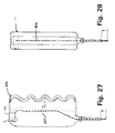
- the gas pressure spring 450 can be actuated by an actuation button 451 provided at its end, which is pushed outwards by means of a compression spring 452.
- a Bowden cable 453 is fastened or stretched over the outside of the button 451 and extends outwards through an opening 454 in the tube 329 on the side opposite the fastened end.
- the handle 456 is preferably ergonomically designed and has a shape adapted to the fingers on one side.
- a guide for the Bowdenzuq 453 is provided in the interior of the handle 456.
- the guide consists of two mating bearing surfaces 457 and 458 shown spaced apart in FIG. 27.
- FIG. 29 shows a view of the cutout or groove 371 formed in the inner tube 329. It can be seen that the groove or slot 371 is milled vertically into the tube, ie the cutting tool always lies vertically on tube 329.
- the slot 371 represents a degenerate thread which is used according to the invention to convert a linear movement into a rotary movement.
- the groove 371 (in particular together with the opposite, crossed groove 372) provides a guide for drive transmission means, which ultimately transmit the linear movement to the element to be adjusted. The reduction can be adjusted by the course of the groove 371.
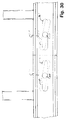
- FIG. Fig. 19 now shows an arrangement in which two adjustment mechanisms according to the invention according to FIG. Fig. 19 are arranged.
- This enables the two adjustment mechanisms according to the invention arranged on the inner tube 329 to make two independent adjustments about one and the same axis, i.e. can execute the central axis of the inner tube 329 (329 ').
- the outer tubes 330, 330 ' can also be connected or can be formed in one piece, which then has the advantage that the load on the respective individual slots or bolts 340, 340' is reduced.
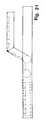
- FIG. 31 shows the use of an adjustment mechanism according to the invention for a head and leg rest of a hospital bed. It should be noted that further adjustment mechanisms according to the invention and / or further joints (not shown) can be provided in order to create an optimal lying surface.
- FIGS. 31 and 32 shows the double use of the angle adjustment mechanism according to the invention for the total height adjustment of the hospital bed.
- two angle adjustment mechanisms according to the invention are arranged on the base of the hospital bed, the angle adjustment movement of which is converted back into a linear movement by means of a mechanism. It can be seen from FIGS. 31 and 32 that the use of the angle adjustment device according to the invention makes it possible to implement all the adjustments required in a patient bed.
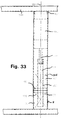
- FIG. 33 shows a variant of the invention in which the concentric tubes (described above) which have been rotated relative to one another are arranged next to one another are, with one of the tubes is stationary.
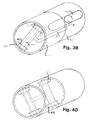
- the operation of the angle adjustment device shown in FIG. 33 can best be understood on the basis of the exemplary embodiment shown in FIG. 13 by the modifications carried out step by step in FIGS. 36 to 40.
- FIG. 33 schematically shows a bed frame 900 to which a cross bar 901 is attached.
- the crossbar 901 consists of two tubes 902, 903.
- the shorter tube 902 is fixed to the frame 900 by welding.
- the tube 902 has, on its inside, oppositely arranged (welded) curved guide rods or rails 904, 905 (indicated schematically by dashed lines).
- Such a bent iron as a guide has the advantage over a slot that no material is spared in the tube, which increases the stability and the load-bearing capacity of the adjusting device.
- a short connecting or bearing sleeve 906, the outside diameter of which corresponds to the inside diameter of the pipes 902, 903, is provided for the rotatable connection of the pipes 902, 903.
- the tube 903 On the side of the tube 903 which bears against the frame 900, the tube 903 is rotatably supported by a further bearing sleeve 907 welded to the frame 900.
- the tube 903 has guides 908, 910 corresponding to the guides 904, 905.
- a linear motor 911 with an adjusting spindle 912 is likewise arranged in the tube 903.
- a tube 913 is moved back and forth by the adjusting spindle 912 along the longitudinal axis 914 of the crossbar 901.
- the tube 913 has two bolts 915, 916, which are guided across the tube 913 and are angled toward the ends.
- the bolt 915 runs along the guides 904, 905.
- the bolt 916 then runs along the guides 908, 910.
- FIG. 36 corresponds to FIG. 13.
- FIGS. 37 and 38 show further developments which, in conjunction with FIGS. 39 and 40, enable an understanding of the exemplary embodiment shown in FIG. 33.
- the sloping slots of the outer tube are replaced by two corresponding sloping guide rod pairs 917, 918 and 919, 920.
- two bearing rings 921, 922, each with a circumferential groove, are provided for bearing against the guides or supports. 38, bars 917 and 919 are omitted.
- two tubes 923, 924 arranged next to one another are provided instead of the tubes arranged concentrically one inside the other.
- a slot 925 of the tube 924 which corresponds to the slot of the inner tube shown in FIGS. 36 to 38, runs a schematically indicated additional bolt 926.
- the bolts 915, 926 are connected by a schematically indicated connection 927, which corresponds to the rod 913, rigidly connected.
- the bolt 926 (FIG. 39) is now designed like the bolt 915, so that instead of the slot 925, guides 928, 929, which correspond to the guides 918, 920, are provided on the inside of the tube 924.
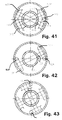
- Fig. 41 two bolts 930, 931 are provided instead of a bolt 915 or 926 (see Fig. 40) in order to reduce the forces on a single bolt.
- Both bolts 930, 931 run with their corresponding bearing rings 933, 934 and 932, 935 with circumferential grooves on common guides 918 and 920.
- the bolts 930, 931 are offset on the connecting tube 913 (which corresponds to the connection 927) in such a way that they are in longitudinally offset positions on the guides without jamming. They are therefore (not shown in the drawing) inclined to one another in the plane of the drawing.
- Spring means can be provided to press the bolts 930, 931 toward the guides 918 and 920 in order to compensate for wear or abrasion caused by the contact of the bolts with the guides.
- the bolts 930, 931 can be connected directly by a tension spring or rotated together by spring force perpendicular to the plane of the drawing, so that they are constantly in contact with the guides.
- Fig. 43 corresponds essentially to Fig. 41, however additional (own) guides 936, 937 are provided for the bolt 931.
- the entrance system 100 has two posts 101, 102.
- a door bracket 103 is pivotally attached to the post or the switching column 101.
- a radar or infrared control not shown, which in the Switching column 101 is integrated and the presence of a customer senses, the door bracket 103 is opened for access by a person.
- the swivel mechanism according to the invention is installed in the switching column 101.
- the system opens to the left or right and can be connected to a PC, in particular for data acquisition and control. This makes it easy to count customers.
- a panic protection is implemented in the system, which enables the door bracket 103 to be opened by forcible opening, and an alarm signal sounds in the event of misuse of the system 100 (leaving the shop through the entrance).
- the switching column 101 has three separate tubes 105, 106, 107 arranged vertically one above the other.
- the middle tube 106 on the outer periphery of which the door bracket 103 is welded, is rotatably connected to the lower tube 105 and the upper tube 107 via two ball bearing arrangements 108 and 109.
- the ball bearing assemblies 108, 109 are identical and aligned with one another.
- the ball bearing arrangements 108, 109 each have four balls (of which only two balls 110, 111 of the upper ball bearing arrangement 108 and two balls 112, 113 of the lower ball bearing arrangement 109 are shown in the sectional view of FIG.
- a drive unit such as. B. a motor 120 with a linear adjusting spindle 120a is arranged in the lower tube 105 and drives a transmission rod 121.
- the transmission rod is guided by guide elements 122, 123.
- the guide elements 122, 123 are formed in an inner tube 130 as disks with openings which correspond to the cross section of the transmission rod 121.
- a clutch assembly 160 which is related in more detail 46 and 47, four bolts (shown schematically in FIG.
- the inner tube 130 has two identical opposite slits at an upper portion thereof, one slit 131 of which can be seen.
- the transmission rod 121 emerges from the tube 130 at the slot 131 and is welded to a spring housing 187 designed as a square tube, which is supported or guided in terms of area by cover plates (not shown) covering the open sides of the slotted tube 130.
- cover plates thus ensure that the slotted tube is closed and form two separate spaces for the passage of cables with the tube 130.
- Support plates 140, 141 are seen to hold the inner tube 130 in front.
- a circuit board for the electronics is shown schematically at 132. It should be noted that the extended state of the linear motor 120 is shown in FIG. 45.
- An adjustment of the gate bracket 103 is achieved by lowering the transmission rod 121.
- FIG. 47 shows a partial sectional view from above of the coupling arrangement 160 designed as a unit.
- the coupling arrangement 160 realizes a coupling that meets the above-mentioned properties of the entrance system, such as, for. B. panic protection, changeover from left to right opening operation.
- the clutch arrangement 160 has a disk 161 with an opening 162, on the inside of which four recesses 166, 167, 168, 169, which are arranged offset by 90 degrees, are formed.
- An inner sleeve 180 circumferentially opposite to the the ends of the fastening flanges 181, 182 are fastened to the disk 161 with two Seeger rings 183, 184.
- the inner sleeve has two rectangular holes (not shown in the drawing) through which two cylinders 185, 186 extend to about a third of their diameter into the recesses 167 and 169, respectively.
- the cylinders 185, 186 are biased into the recesses 167 and 169 by a compression spring 171 arranged in a spring housing 187 via two plates 188 and 189, respectively.
- the thickness of the spring housing 187 denoted by D corresponds to the width of the slot 131.
- the inner tube 130 slotted on both sides extends through the opening 162 beyond the coupling arrangement 160 (from the plane of the drawing in FIG. 47).
- a stationary inner tube 200 has on its outer circumference two guides 201, 202 arranged opposite one another, which correspond to the guides 126, 127 of FIG. 45.
- receiving elements 203, 204 FIG. 48, with the disadvantage of static friction but the advantage of low manufacturing costs
- Fig. 47 described "bolt + washer” assemblies (one 205 of which is shown in Fig. 49) attached to the inner circumference of the central tube 210.
- Receiving elements 211, 212 (FIG. 48) or “bolt + washer” arrangements (FIG.
- Variants of the adjustment mechanism according to the invention are disclosed with a rod (at least one groove (or slot)) (alternatively: twisted steel strip), with at least two tubes (rotatably connected) arranged concentrically one above the other and next to one another. All combinations of the described arrangements are also intended to be disclosed, e.g. B. a construction with two concentrically arranged tubes of which the inner is grooved and the outer has guides on its inner wall.
- the groove (s) (or slots or one- or two-sided systems) can be designed obliquely to the axis of rotation straight, ie with a constant slope, or with a variable slope in order to adapt to changing loads, as in connection with FIGS. 1-3 described with respect to the changing vertical component of the weight has been. The same applies to the twisting of a twisted element, such as the strip steel described above.
- the bolts described above can be prestressed into the boundary surfaces of the grooves by spring means in order to compensate for wear or abrasion.
- the invention was explained on the basis of preferred exemplary embodiments in connection with a hospital and nursing bed and an entrance system.
- numerous modifications and refinements are possible for the person skilled in the art without departing from the concept on which the invention is based.
- the features and details described in connection with different embodiments of the invention can also be combined with one another.
- the invention is not restricted to the applications described.
- the adjustment mechanism according to the invention can generally be used for a backrest (arm, back, leg rest) in garden furniture, home furniture ...
- the entrance system can not only in shops, such as. B. a supermarket, are used, but also for example for access to a ski lift or to events.
- the adjustment mechanism according to the invention can also be used for a translational movement, in particular a height adjustment, the advantage in this case being that the rotation and height adjustment can be realized with the same components.
- an element to be adjusted on the tube such as a backrest or a bracket, does not necessarily have to be attached, but only an adjustment of the tube is intended depending on the application.
Landscapes
- Health & Medical Sciences (AREA)
- General Health & Medical Sciences (AREA)
- Nursing (AREA)
- Invalid Beds And Related Equipment (AREA)
Applications Claiming Priority (6)
| Application Number | Priority Date | Filing Date | Title |
|---|---|---|---|
| DE19513031 | 1995-04-06 | ||
| DE19513031 | 1995-04-06 | ||
| DE19521606 | 1995-06-18 | ||
| DE19521606 | 1995-06-18 | ||
| DE19600430A DE19600430A1 (de) | 1995-01-08 | 1996-01-08 | Winkelverstellmechanismus |
| DE19600430 | 1996-01-08 |
Publications (2)
| Publication Number | Publication Date |
|---|---|
| EP0736699A2 true EP0736699A2 (fr) | 1996-10-09 |
| EP0736699A3 EP0736699A3 (fr) | 1996-12-11 |
Family
ID=27215025
Family Applications (1)
| Application Number | Title | Priority Date | Filing Date |
|---|---|---|---|
| EP96105499A Withdrawn EP0736699A3 (fr) | 1995-04-06 | 1996-04-05 | Dispositif d'ajustement angulaire |
Country Status (1)
| Country | Link |
|---|---|
| EP (1) | EP0736699A3 (fr) |
Family Cites Families (5)
| Publication number | Priority date | Publication date | Assignee | Title |
|---|---|---|---|---|
| FR2036793A1 (fr) * | 1969-04-01 | 1970-12-31 | Pigeon Jacques | |
| FR2161491A5 (fr) * | 1971-11-26 | 1973-07-06 | Jansen Gmbh | |
| DE3400637C2 (de) * | 1984-01-11 | 1986-06-19 | ROKADO Metall-Holz-Kunststoff GmbH & Co KG, 4755 Holzwickede | Vorrichtung zum Verstellen und Arretieren des Kopfteiles eines Bettrahmens |
| US4853990A (en) * | 1986-12-29 | 1989-08-08 | Mechanical Backrest, Inc. | Mechanical backlift |
| DE8707252U1 (de) * | 1987-05-20 | 1987-11-12 | Hanel, Eugen, 4100 Duisburg | Gewindeform für einen Drehtrieb |
-
1996
- 1996-04-05 EP EP96105499A patent/EP0736699A3/fr not_active Withdrawn
Also Published As
| Publication number | Publication date |
|---|---|
| EP0736699A3 (fr) | 1996-12-11 |
Similar Documents
| Publication | Publication Date | Title |
|---|---|---|
| DE2732654C3 (de) | Gelenkbeschlag für Leiteiteile | |
| DE69310834T2 (de) | Vorrichtung für die Neigungsverstellung von Bett- oder Sofateilen | |
| DE69224146T2 (de) | Schmalle Ausziehführung für Schubladen | |
| EP2873344B1 (fr) | Meuble doté d'un pied réglable en hauteur | |
| DE102008037285A1 (de) | Tisch mit einer schwenkbaren Tischplatte | |
| DE3431386C2 (fr) | ||
| EP0589190B1 (fr) | Appui-bras pour meubles d'assise | |
| EP0786952B1 (fr) | Support de siege pour chaises de bureau ou analogue | |
| DE9418079U1 (de) | Freitragendes Schiebetor | |
| EP3400834A1 (fr) | Ferrure pivotante et meuble | |
| EP3768993A1 (fr) | Entraînement de meubles par moteur électrique pourvu d'un ensemble de transmission à arbre intermédiaire | |
| EP2186500B1 (fr) | Dispositif de sécurité pour lits de malades et de soins | |
| WO2019180218A1 (fr) | Entraînement à moteur électrique pour meuble | |
| DE69101266T2 (de) | Anzeigevorrichtung. | |
| EP0995371B1 (fr) | Chaise de bureau avec assise réglable en inclinaison | |
| EP0000499B1 (fr) | Ferrure d'articulation pour échelles | |
| EP3116347B1 (fr) | Siège rotatif | |
| EP3672451B1 (fr) | Chaise avec un élément de libération | |
| DE19647544C1 (de) | Antriebsvorrichtung für hin- und hergehende Schwenkbewegungen | |
| EP1662159A1 (fr) | Système de guide linéaire avec élément de positionnement | |
| EP1106110B1 (fr) | Accoudoir à hauteur réglable pour siège notamment pour chaises de bureau | |
| DE60003166T2 (de) | Kippvorrichtung | |
| DE3238889A1 (de) | Befestigungsvorrichtung zur schwenkbaren befestigung eines gegenstands, insbesondere haltegriffs, an einer wand od. dgl. | |
| EP1584264B1 (fr) | Système d'entrainement réglable en hauteur notamment pour meubles | |
| DE19948579C2 (de) | Pendeltür für Durchgangsanlagen |
Legal Events
| Date | Code | Title | Description |
|---|---|---|---|
| PUAI | Public reference made under article 153(3) epc to a published international application that has entered the european phase |
Free format text: ORIGINAL CODE: 0009012 |
|
| AK | Designated contracting states |
Kind code of ref document: A2 Designated state(s): DE FR GB IE |
|
| PUAL | Search report despatched |
Free format text: ORIGINAL CODE: 0009013 |
|
| AK | Designated contracting states |
Kind code of ref document: A3 Designated state(s): DE FR GB IE |
|
| 17P | Request for examination filed |
Effective date: 19970509 |
|
| STAA | Information on the status of an ep patent application or granted ep patent |
Free format text: STATUS: THE APPLICATION IS DEEMED TO BE WITHDRAWN |
|
| 18D | Application deemed to be withdrawn |
Effective date: 19981103 |