EP0736685B1 - Verteilerkraftstoffeinspritzpumpe - Google Patents
Verteilerkraftstoffeinspritzpumpe Download PDFInfo
- Publication number
- EP0736685B1 EP0736685B1 EP96302180A EP96302180A EP0736685B1 EP 0736685 B1 EP0736685 B1 EP 0736685B1 EP 96302180 A EP96302180 A EP 96302180A EP 96302180 A EP96302180 A EP 96302180A EP 0736685 B1 EP0736685 B1 EP 0736685B1
- Authority
- EP
- European Patent Office
- Prior art keywords
- hole
- distribution member
- holes
- control sleeve
- communication
- Prior art date
- Legal status (The legal status is an assumption and is not a legal conclusion. Google has not performed a legal analysis and makes no representation as to the accuracy of the status listed.)
- Expired - Lifetime
Links
- 238000002347 injection Methods 0.000 title claims description 135
- 239000007924 injection Substances 0.000 title claims description 135
- 239000000446 fuel Substances 0.000 title claims description 87
- 238000009826 distribution Methods 0.000 claims description 66
- 238000004891 communication Methods 0.000 claims description 38
- 230000006835 compression Effects 0.000 claims description 17
- 238000007906 compression Methods 0.000 claims description 17
- 238000000034 method Methods 0.000 claims description 16
- 230000008569 process Effects 0.000 claims description 16
- 230000008859 change Effects 0.000 claims description 3
- 238000006073 displacement reaction Methods 0.000 claims 1
- 239000000779 smoke Substances 0.000 description 6
- 238000002485 combustion reaction Methods 0.000 description 4
- 230000002517 constrictor effect Effects 0.000 description 4
- 230000007246 mechanism Effects 0.000 description 4
- 238000013459 approach Methods 0.000 description 2
- 230000008878 coupling Effects 0.000 description 2
- 238000010168 coupling process Methods 0.000 description 2
- 238000005859 coupling reaction Methods 0.000 description 2
- 230000007423 decrease Effects 0.000 description 2
- 238000010586 diagram Methods 0.000 description 2
- 230000006872 improvement Effects 0.000 description 2
- 239000002828 fuel tank Substances 0.000 description 1
- 238000007493 shaping process Methods 0.000 description 1
Images


Classifications
-
- F—MECHANICAL ENGINEERING; LIGHTING; HEATING; WEAPONS; BLASTING
- F02—COMBUSTION ENGINES; HOT-GAS OR COMBUSTION-PRODUCT ENGINE PLANTS
- F02M—SUPPLYING COMBUSTION ENGINES IN GENERAL WITH COMBUSTIBLE MIXTURES OR CONSTITUENTS THEREOF
- F02M37/00—Apparatus or systems for feeding liquid fuel from storage containers to carburettors or fuel-injection apparatus; Arrangements for purifying liquid fuel specially adapted for, or arranged on, internal-combustion engines
-
- F—MECHANICAL ENGINEERING; LIGHTING; HEATING; WEAPONS; BLASTING
- F02—COMBUSTION ENGINES; HOT-GAS OR COMBUSTION-PRODUCT ENGINE PLANTS
- F02M—SUPPLYING COMBUSTION ENGINES IN GENERAL WITH COMBUSTIBLE MIXTURES OR CONSTITUENTS THEREOF
- F02M41/00—Fuel-injection apparatus with two or more injectors fed from a common pressure-source sequentially by means of a distributor
- F02M41/08—Fuel-injection apparatus with two or more injectors fed from a common pressure-source sequentially by means of a distributor the distributor and pumping elements being combined
- F02M41/14—Fuel-injection apparatus with two or more injectors fed from a common pressure-source sequentially by means of a distributor the distributor and pumping elements being combined rotary distributor supporting pump pistons
- F02M41/1405—Fuel-injection apparatus with two or more injectors fed from a common pressure-source sequentially by means of a distributor the distributor and pumping elements being combined rotary distributor supporting pump pistons pistons being disposed radially with respect to rotation axis
- F02M41/1411—Fuel-injection apparatus with two or more injectors fed from a common pressure-source sequentially by means of a distributor the distributor and pumping elements being combined rotary distributor supporting pump pistons pistons being disposed radially with respect to rotation axis characterised by means for varying fuel delivery or injection timing
-
- F—MECHANICAL ENGINEERING; LIGHTING; HEATING; WEAPONS; BLASTING
- F02—COMBUSTION ENGINES; HOT-GAS OR COMBUSTION-PRODUCT ENGINE PLANTS
- F02M—SUPPLYING COMBUSTION ENGINES IN GENERAL WITH COMBUSTIBLE MIXTURES OR CONSTITUENTS THEREOF
- F02M45/00—Fuel-injection apparatus characterised by having a cyclic delivery of specific time/pressure or time/quantity relationship
- F02M45/02—Fuel-injection apparatus characterised by having a cyclic delivery of specific time/pressure or time/quantity relationship with each cyclic delivery being separated into two or more parts
- F02M45/04—Fuel-injection apparatus characterised by having a cyclic delivery of specific time/pressure or time/quantity relationship with each cyclic delivery being separated into two or more parts with a small initial part, e.g. initial part for partial load and initial and main part for full load
- F02M45/06—Pumps peculiar thereto
Definitions
- the present invention relates to a distributor type fuel injection pump provided with a pilot injection mechanism, used for supplying fuel to an engine, and more specifically, it relates to an inner cam, distributor type fuel injection pump (VR pump) which causes plungers to make reciprocal movement in the direction of the radius of a rotating distribution member and a distributor type fuel injection pump (VE pump) which distributes fuel by causing a distribution member to make rotating and reciprocal movement.
- VR pump distributor type fuel injection pump
- VE pump distributor type fuel injection pump
- a concentric inner cam ring 1 is provided around a fuel distribution rotor 4 (distribution member) and force feed plungers 21 and 22 are provided on the cam surfaces formed on the inside of the inner cam ring 1 via a roller or the like so that the force feed plungers 21 and 22 can make reciprocal movement in the direction of the radius of the fuel distribution rotor 4.
- a pump chamber 2 compression space
- intake holes 51 ⁇ 54 through which fuel is taken into the pump chamber 2 during an intake process
- a distribution port 6 which, during a force feed process, delivers fuel that has been pressurized in the pump chamber 2 and overflow ports 71 ⁇ 74, which cut off the fuel delivery, are formed.
- a ring-like member 7 (control sleeve) is externally fitted on the fuel distribution rotor 4, covering the overflow ports 71 ⁇ 74 and by moving this ring-like member in the direction of the axis, the cut off timing during the force feed process can be adjusted to vary the fuel injection quantity.
- a plunger 7 (distribution member) is secured to a cam disk 8 which rotates in synchronization with an engine to cause the plunger 7 to rotate and, at the same time, to make reciprocal movement in correspondence to the cam surface of the cam disk.
- the front end of the plunger faces a space 10 which constitutes a compression space and in the plunger, a longitudinal groove 11 for taking fuel into the space 10 during the intake process, a distribution longitudinal groove 14 for delivering fuel which as been pressurized in the space 10 during the force feed process and a cut off port 17 for cutting off fuel delivery, are formed.
- a control sleeve is externally fitted on the plunger 7, covering the cut off port 17 and, by moving this control sleeve in the direction of the axis, cut off timing during the force feed process is adjusted to vary the fuel injection quantity.
- an object of the present invention is to provide a distributor type fuel injection pump in which the requirements described above can be satisfied with a simple mechanism without having to add new members.
- the applicant of the present invention through extensive research into mechanical structures that might achieve the object described above, has completed the present invention based upon the observation that pilot injection can be made to occur during low speed rotation and can be canceled during high speed rotation by forming a hole for diverting fuel during part of the force feed period and shaping this hole in such a manner that the fuel is less likely to be diverted as the speed increases and that pilot injection can be made to occur when the injection quantity is small and can be canceled when the injection quantity is large, by ensuring that the effective area of the hole becomes reduced as the injection quantity increases.
- the distributor type fuel injection pump according to the present invention is either a VR or VE type fuel injection pump with a control sleeve externally fitted around a distribution member that distributes compressed fuel and is provided with first through holes, the number of which corresponds to the number of distributions, with slits extending from the first through holes, a second through hole that communicates with the first through holes sequentially and a third through hole that communicates with the slits during a part of the force feed period formed at the other of either the control sleeve or distribution member.
- the size of the area where the slits and the third through hole overlap in correspondence to the position of the control sleeve. More specifically, as the control sleeve travels further in the direction in which the fuel quantity increases, the overlapping area of the slits and third through hole is reduced. It is also acceptable to make the first through holes and the third through hole communicate with each other earlier when the control sleeve is positioned in the vicinity of the small injection quantity position, compared to when the control sleeve is at other positions.
- the second through hole communicates with the first through holes sequentially to distribute the fuel and the intake process, in which the fuel is taken in, is caused to occur during the period of time in which a first through hole communicates with the second through hole, whereas the force feed process is caused to take place during the period of time after the second through hole is disconnected from the first through hole and before the second through hole comes into communication with the next first through hole.
- this force feed process after the communication between the second through hole and a first through hole is cut off, force feed of the fuel starts, and when a slit and the third through hole come into communication during this force feed process, the compressed fuel is diverted temporarily.
- force feed of the fuel takes place until the slit becomes disconnected from the third through hole and a first through hole comes into communication with the second through hole again, and when the first through hole comes into communication with the second through hole, the fuel is diverted, to stop the delivery.
- the communication between the slits and the third through hole ensures that while the distribution member rotates at low speed, the compressed fuel is diverted in sufficient quantity to cause pilot injection preceding the main injection, while it is rotating at high speed, the diversion of the compressed fuel is reduced, due to the contracting of the slits, to the extent that the pilot injection cannot be distinguished from the main injection and, as a result, only the main injection is performed.
- the pilot injection quantity is reduced as the main injection quantity becomes reduced, thereby eliminating the problem of the pilot injection remaining at a constant quantity even when the main injection quantity has become reduced.
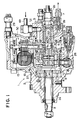
- FIG. 1 is a cross section of a VR type distributor type fuel injection pump according to the present invention.
- FIG. 2 is an enlarged cross section of the cam ring 26 shown in FIG. 1 and members provided inside it, viewed from the direction of the axis of the distribution member 8.
- FIG. 3 is an enlarged cross section showing the distribution member 8 and members surrounding it.
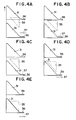
- FIG. 4 shows the changes in positional relationships among the inflow/outflow ports 31, the slits 36, the intake-cutoff hole 35 and the pilot port 37 as the distribution member rotates, with FIG. 4A illustrating fuel intake, FIG. 4B illustrating pilot injection, FIG. 4C illustrating pilot diversion, FIG. 4D illustrating main injection and FIG. 4E illustrating main diversion.
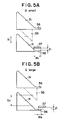
- FIG. 5 illustrates the positional relationships among the inflow/outflow ports 31, the slits 36, the intake-cutoff hole 35 and the pilot port 37 as the position of the control sleeve is adjusted.
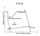
- FIG. 6 is a characteristics diagram showing the relationship between the injection quantity (Q) and the pump rotation rate (Np).
- FIG. 7 shows the injection rate characteristics (dQ /dt) at points A, B, C and D in FIG. 6.
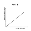
- FIG. 8 is a characteristics diagram showing the relationship between the injection quantity and the control sleeve position.
- FIG. 1 which shows an inner cam, distributor type fuel injection pump
- a distributor type fuel injection pump 1 is provided with a drive shaft 3 inserted in a pump housing 2, with one end of this drive shaft 3 projecting out to the outside of the pump housing 2 to receive drive torque from an engine (not shown) so that it rotates in synchronization with the engine (at a rotation rate that is half the rotation rate of the engine).
- the other end of the drive shaft 3 extends inside the pump housing 2 and a feed pump 4 is linked with the drive shaft 3 so that fuel can be supplied by the feed pump 4 from the low pressure fuel region, which is to the explained later, to a chamber 6.
- the pump housing 2 comprises a housing member 2a through which the drive shaft 3 is inserted, a housing member 2b that is mounted on the housing member 2a and is provided with a delivery valve 7 and a housing member 2c that blocks the opening end of the housing member 2b and is provided on an extended line from the distribution member 8.
- the chamber 6 is formed by being enclosed by a supporting member 9 provided inside the pump housing, a wall member 10, which holds the supporting member 9 where the supporting member 9 passes through it and an adapter 11, which is to be explained later.
- the chamber 6 communicates with a governor housing chamber 13 which is defined by a governor housing 12.
- a side portion of the supporting member 9 projects out to be fitted in the housing member 2b.
- a distribution member 8 is supported at a through hole in the supporting member 9 in such a manner that it can rotate freely, with its base end portion linked to the drive shaft 3 via a coupling 14 so that it rotates only with the rotation of the drive shaft 3.
- plungers 22 are inserted in the direction of the radius (radial direction) in such a manner that they can slide freely.
- each plunger 22 is provided on a flat plane over, for instance, 90° intervals and the front end of each plunger 22 faces a compression space 23, which is provided at the center of the base end portion of the distribution member 8, so as to seal it.
- the base ends of the plungers 22 slide against the internal surface of a ring-like cam ring 26 via shoes 24 and rollers 25.
- This cam ring 26 is provided concentrically to and around the distribution member 8 and is provided with cam surfaces 26a on the inside thereof, the number of which corresponds to the number of cylinders in the engine.
- the cam ring 26 if it is constituted in correspondence to a four cylinder engine, is provided with projected surfaces every 90° on its inside and, as a result, the four plungers 22 will travel simultaneously toward the compression space 23 to compress it by contracting it and will travel away from the center of the cam ring 26 simultaneously.
- a ring-like adapter 11 is externally fitted on the distribution member 8 with a good oil-tight seal in such a manner that it can rotate freely and the rotation of this adapter 11 is restricted with a portion of its circumferential edge being held at the cam ring 26 so that it can only rotate along with the cam ring 26.
- the adapter 11 is mounted at the supporting member 9 with a good oil-tight seal in such a manner that it can rotate freely.
- a fuel inflow port 49 which communicates with a fuel tank, is formed at the housing member 2b and fuel that flows in through this fuel inflow port 49 is led toward the intake side of the feed pump 4 via the space formed around the supporting member 9, the wall member 10 and the adapter 11, the space formed between the cam ring 26 and the distribution member 8, a passage formed around the coupling 14 and the like, and these spaces and the passage constitute a low pressure fuel region 5 which extends from the fuel inflow port 49 to the feed pump 4.
- fuel that has been compressed by the feed pump 4 is led to the chamber 6 through a passage 27 formed in the upper portion of the pump housing and a gap 28 formed between the pump housing 2 and the governor housing 12 that is mounted on the pump housing 2, and it is also led to an overflow valve 29 via the governor housing chamber 13 so that a high pressure fuel region 6 is formed with these communicating elements.
- a longitudinal hole 30 is formed in the direction of the axis, communicating with the compression space 23, inflow/outflow ports 31, the number of which corresponds to the number of cylinders, communicating with the longitudinal hole 30 and opening onto the circumferential surface of the distribution member 8 and a distribution port making possible communication between distribution passages 32, formed in the supporting member 9 and the housing member 2b, and the longitudinal hole 30 are formed. As shown in FIG.
- the portions of the inflow/outflow ports 31 that open onto the surface of the distribution member 8 are triangular, with the side of each triangle toward the rear in the direction of rotation running parallel to the direction of the axis of the distribution member 8 and the side toward the front, constituting the hypotenuse, which inclines at a specific angle relative to the direction of the axis of the distribution member 8.
- a control sleeve 34 is externally fitted on the distribution member 8, covering the inflow/outflow ports 31 in such a manner that it can slide freely.
- an intake-cutoff hole 35 which can communicate with the inflow/outflow ports 31, is formed in the control sleeve 34.
- the intake-cutoff hole 35 is formed in a triangular shape, with the side that determines the timing with which it starts to communicate with an inflow/outflow port 31 constituting the hypotenuse, which inclines at a specific angle relative to the direction of the axis of the distribution member 8, and the side that determines the timing with which its communication with the inflow/outflow port 31 ends, running parallel to the direction of the axis of the distribution member 8.
- a slit 35 extends in the direction of the axis and a pilot port 37, which can communicate with these slits, is formed in the control sleeve 34.
- This pilot port 37 is formed in a slit shape, extending in the direction of the axis and it is ensured that the pilot port 37 communicates with a slit 36 before an inflow/outflow port 31 comes into communication with the intake-cutoff hole 35.
- the area where the pilot port 37 overlaps with the slit 35 becomes reduced as the control sleeve 34 travels further in the direction in which the injection quantity increases, and when the control sleeve 34 is at a small injection quantity position, the pilot port 37 is positioned at a location where it engages the hypotenuse of an inflow/outflow port so that it communicates with the inflow/outflow port 31 before it communicates with slit 36.
- a ball portion 39 of a shaft 51 of an electric governor 50 which is accommodated in the governor housing chamber 13, is connected to the control sleeve 34 and that when the shaft 51 is rotated by a signal from the outside, the control sleeve 34 is caused to travel in the direction of the axis of the distribution member 8.
- a groove 34a which extends in the direction of the axis is formed with a portion of the adapter 11 connected in this groove 34a to ensure that the phases of the adapter 11 and the control sleeve 34 are always maintained at a specific phase relationship.
- the distribution port 33 becomes aligned with one of the distribution passages 32 and the compressed fuel is discharged to a delivery valve 7 via a distribution passage 32.
- the fuel which is delivered via the delivery valve 7 is then sent to an injection nozzle via an injection pipe (not shown) and is injected from the injection nozzle into a cylinder of the engine.
- the timing with which the inflow/outflow ports 31 come into communication with the intake-cutoff hole 35 can be varied by adjusting the position of the control sleeve 34.
- injection end i.e., injection quantity
- the control sleeve 34 is made to travel further to the left in FIG. 3 (toward the base end portion of the distribution member 8) the injection quantity is reduced, whereas, as it is made to travel further to the right (toward the front end portion of the distribution member 8) the injection quantity is increased.
- the effective stroke is small, the size of the area over which slits 36 and the pilot port 37 overlap each other is large and the pump rotation rate ( Np) is low. Consequently, when a slit 36 comes into communication with the pilot port 37, the compressed fuel is diverted in sufficient quantity to halt the injection temporarily and, as shown in FIG. 7A, a pilot injection takes place prior to the main injection. With this pilot injection, ignition of the main injection will be smooth. As a result, combustion noise in the idling range is reduced and the amount of white smoke generated is reduced.
- the size of the area over which the slits 36 overlap the pilot port 37 is smaller than that during idling and the constricting effect still occurs to a certain extent, because the pump rotation is at medium level.
- the quantity of compressed fuel diverted is smaller than the quantity diverted during idling and, as shown in FIG. 7D, although the injection will be somewhat inhibited at the point in time when a slit 36 comes into communication with the pilot port 37, the operation shifts to the main injection without being halted.
- the pilot port 37 moves closer to the hypotenuse of the inflow/outflow ports 35 as the control sleeve 34 approaches the small injection quantity position and the inflow/outflow port 31 begins to communicate with the pilot port 37 before the slit 36 communicates with the pilot port 37, the pilot injection is reduced as the control sleeve 34 travels further toward the small injection quantity position.
- the injection quantity Q can be made to be almost in proportion to the control sleeve position, as indicated with the solid line characteristics curve in FIG. 8.
- first through holes the number of which corresponds to the number of distributions and slits that extend from these through holes are provided at either the distribution member or the control sleeve and, at the other one of the distribution member or the control sleeve, a second through hole that communicates with the first through holes sequentially and a third through hole that communicates with the slits during part of the force feed period are provided.
- the size of the area over which the slit and the third through hole overlap with each other when they communicate is varied in correspondence to the control sleeve position in such a manner that, as the control sleeve moves further toward the direction in which the fuel quantity increases, the size of the overlapping area of the slit and the third through hole is reduced.
- ignition can be performed smoothly with pilot injection in the idling range and the no-load range during low speed, low load operation, reducing the generation of white smoke due to flame-out, also reducing NOx, and reducing the combustion noise because of the smooth engine ignition in the idling range. Furthermore, since pilot injection can be canceled during low speed, high load operation, the generation of black smoke can be prevented and improvement in both torque and fuel efficiency can be achieved as well.
- the pilot injection would continue in a specific quantity even when the main injection quantity is reduced, by making a first through hole and the third through hole communicate with each other earlier as the control sleeve approaches the small injection quantity position, the pilot injection quantity is reduced as the main injection quantity decreases and, as a result, the relationship between the entire injection quantity and the control sleeve position is made almost linear.
Landscapes
- Engineering & Computer Science (AREA)
- Chemical & Material Sciences (AREA)
- Combustion & Propulsion (AREA)
- Mechanical Engineering (AREA)
- General Engineering & Computer Science (AREA)
- Fuel-Injection Apparatus (AREA)
Claims (12)
- Verteilerkraftstoffeinspritzpumpe, bestehend ausdadurch gekennzeichnet, daßeinem Pumpengehäuse (2),einer Kammer (6), die im Pumpengehäuse ausgebildet und mit Kraftstoff gefüllt ist,einem Kompressionsraum (23) zum Komprimieren des Kraftstoffs,einem Verteilerelement (8), das sich synchron mit einem Motor dreht, um den im Kompressionsraum (23) komprimierten Kraftstoff zu verteilen,einer Steuerhülse (34), die extern und verschiebbar um das Verteilerelement (8) aufgesetzt und in der Kammer (6) angeordnet ist,einer Längsbohrung (30), die im Verteilerelement (8) ausgebildet ist und mit dem Kompressionsraum (23) in Verbindung steht,ersten Durchgangsbohrungen (31), die in einen der Verteilerelement- und Steuerhülsenteile (8, 34) ausgebildet sind und deren Anzahl der Anzahl der Zylinder des Motors entspricht, undeiner zweiten Durchgangsbohrung (35), die im anderen der Verteilerelement- und Steuerhülsenteile (8, 34) ausgebildet ist und mit einer der ersten Durchgangsbohrungen (31) verbunden ist, um die Längsbohrung (30) und die Kammer (6) zu verbinden,ein Öffnungsbereich der ersten Durchgangsbohrungen (31) einen Schlitz hat, der längs einer Axialrichtung des Verteilerelementteils (8) verläuft und mit jeder der ersten Durchgangsbohrungen (31) verbunden ist,einer dritten Durchgangsbohrung (37), die im anderen der Verteilerelement- und Steuerhülsenteile (8, 34) ausgebildet ist, unddie dritte Durchgangsbohrung (37) mit einem der Schlitze (36) verbunden ist, um die Längsbohrung (30) und die Kammer (6) während eines Teils der Auslaßperiode zu verbinden, wenn die Verbindung zwischen einer der ersten Durchgangsbohrungen (31) und der zweiten Durchgangsbohrung (35) unterbrochen ist.
- Verteilerkraftstoffeinspritzpumpe nach Anspruch 1, bei der ein Überlappungsbereich zwischen den Schlitzen (36) und der dritten Durchgangsbohrung (37) entsprechend einer Position der Steuerhülse (34) geändert wird.
- Verteilerkraftstoffeinspritzpumpe nach Anspruch 1, bei der ein Überlappungsbereich zwischen den Schlitzen (36) und der dritten Durchgangsbohrung (37) reduziert wird, wenn sich die Steuerhülse (34) weiter in der Richtung verstellt, in der die Kraftstoffmenge zunimmt.
- Verteilerkraftstoffeinspritzpumpe nach Anspruch 3, bei der die dritte Durchgangsbohrung (37) als Schlitz ausgebildet ist, der in der Axialrichtung des Verteilerelements (8) verläuft.
- Verteilerkraftstoffeinspritzpumpe nach Anspruch 1, weiterhin aufweisend mehrere Kolben (22), die in radialen Richtungen des Verteilerelements (8) so verschiebbar vorgesehen sind, daß sie zum Kompressionsraum (23) weisen,einen Steuerring (26), der konzentrisch zu dem und um das Steuerelement (8) vorgesehen ist, undRollen (25), die zwischen den Basisabschnitten der Kolben (22) und Steuerflächen vorgesehen sind, die an einer Innenfläche des Steuerrings (26) vorgesehen sind,wobei die Kolben (22) in radialen Richtungen des Verteilerelements (8) bei Drehung des Verteilerelements (8) eine Reziprokbewegung durchführen, um die volumetrische Kapazität des Kompressionsraums (23) zu ändern.
- Verteilerkraftstoffeinspritzpumpe nach Anspruch 5, bei der ein Öffnungsbereich jeder der ersten Durchgangsbohrungen (31) eine Dreieckform hat, wobei eine Seite der Dreieckform rückwärts in einer Drehrichtung des Verteilerelements (8) parallel zur axialen Richtung des Verteilerelements (8) verläuft, und eine Seite der Dreieckform vorwärts in der Drehrichtung unter einem speziellen Winkel relativ zur axialen Richtung des Verteilerelements (8) geneigt ist,ein Öffnungsbereich der zweiten Durchgangsbohrung (35) in Dreieckform ausgebildet ist, eine Seite der Dreieckform zur Bestimmung des Zeitpunkts für den Beginn der Verbindung mit einer der ersten Durchgangsbohrungen (31) unter einem speziellen Winkel relativ zur Axialrichtung des Verteilerelements (8) geneigt ist, und eine Seite der Dreieckform zur Bestimmung eines Zeitpunkts für die Beendigung der Verbindung mit einer der Durchgangsbohrungen (31) parallel zur Axialrichtung des Verteilerelements (8) verläuft, unddie Verstellung der Steuerhülse (34) relativ zum Verteilerelement (8) einen effektiven Hub von dem Zeitpunkt an, wenn die zweite Durchgangsbohrung (35) die Verbindung mit einer der ersten Durchgangsbohrungen (31) beendet, bis zum Zeitpunkt, wenn die zweite Durchgangsbohrung (35) die Verbindung mit der nächsten der ersten Durchgangsbohrungen (31) und einen Überlappungsbereich zwischen den Schlitzen (36) und der dritten Durchgangsbohrung (37) beginnt, ändert.
- Verteilerkraftstoffeinspritzpumpe nach Anspruch 6, bei der der effektive Hub klein gemacht und der Überlappungsbereich zwischen den Schlitzen (36) und der dritten Durchgangsbohrung (37) in einem Bereich groß gemacht wird, in dem die Drehzahl des Motors niedrig und die Einspritzmenge klein ist.
- Verteilerkraftstoffeinspritzpumpe nach Anspruch 6, bei der der effektive Hub groß und der Überlappungsbereich zwischen den Schlitzen (36) und der dritten Durchgangsbohrung (37) in einem Bereich klein gemacht wird, in dem die Drehzahl des Motors niedrig und die Einspritzmenge groß ist.
- Verteilerkraftstoffeinspritzpumpe nach Anspruch 6, bei der der effektive Hub groß und der Überlappungsbereich zwischen den Schlitzen (36) und der dritten Durchgangsbohrung (37) in einem Bereich klein gemacht wird, in dem die Drehzahl der Maschine hoch und die Einspritzmenge groß ist.
- Verteilerkraftstoffeinspritzpumpe nach Anspruch 1, bei der bei einem Ansaugvorgang einer der ersten Durchgangsbohrungen (31) und die zweite Durchgangsbohrung (35) miteinander verbunden sind, so daß der Kraftstoff in der Kammer (6) dem Kompressionsraum (23) zugeführt wird,bei einem Druckfördervorgang die Verbindung zwischen einer der ersten Durchgangsbohrungen (31) und der zweiten Durchgangsbohrung (35) unterbrochen wird, so daß der im Kompressionsraum (23) komprimierte Kraftstoff der erste Druckförderzustand wird, um eine Voreinspritzung zu beginnen,der Schlitz (36) einer der ersten Durchgangsbohrungen (31) mit der dritten Durchgangsbohrung (37) verbunden ist, so daß der Kompressionsraum (23) und die Kammer (6) miteinander verbunden sind, um die Voreinspritzung zu beenden,die Verbindung zwischen dem Schlitz (36) und einer der ersten Durchgangsbohrungen (31) und der dritten Durchgangsbohrung (37) unterbrochen wird, so daß der im Kompressionsraum (23) komprimierte Kraftstoff ein zweiter Druckförderzustand wird, um die Haupteinspritzung zu beginnen, und danndie zweite Durchgangsbohrung (35) mit der nächsten der ersten Durchgangsbohrungen (31) verbunden ist, so daß der im Kompressionsraum (23) komprimierte Kraftstoff in die Kammer (6) strömt, um den zweiten Förderzustand zu beenden, so daß der Druckfördervorgang beendet wird.
- Verteilerkraftstoffeinspritzpumpe nach Anspruch 1, bei der die Steuerhülse (34) nahe einer Position für eine geringe Einspritzmenge ist, wobei die Verbindung zwischen einer der ersten Durchgangsbohrungen (31) und der dritten Durchgangsbohrung (37) eher beginnt, als wenn die Steuerhülse (34) in den anderen Positionen ist, wobei eine Voreinspritzmenge nahezu proportional zur Position der Steuerhülse (34) gemacht wird.
- Verteilerkraftstoffeinspritzpumpe nach Anspruch 6, bei der, wenn die Steuerhülse (34) nahe einer Position für eine geringe Einspritzmenge ist, die dritte Durchgangsbohrung (37) an der Hypotenuse der Dreieckform einer der ersten Durchgangsbohrungen (31) angelangt, bevor die dritte Durchgangsbohrung (37) am Schlitz (36) einer der ersten Durchgangsbohrungen (31) angelangt.
Applications Claiming Priority (3)
| Application Number | Priority Date | Filing Date | Title |
|---|---|---|---|
| JP7101743A JPH08270521A (ja) | 1995-04-03 | 1995-04-03 | 分配型燃料噴射ポンプ |
| JP10174395 | 1995-04-03 | ||
| JP101743/95 | 1995-04-03 |
Publications (3)
| Publication Number | Publication Date |
|---|---|
| EP0736685A2 EP0736685A2 (de) | 1996-10-09 |
| EP0736685A3 EP0736685A3 (de) | 1997-03-19 |
| EP0736685B1 true EP0736685B1 (de) | 1999-11-24 |
Family
ID=14308735
Family Applications (1)
| Application Number | Title | Priority Date | Filing Date |
|---|---|---|---|
| EP96302180A Expired - Lifetime EP0736685B1 (de) | 1995-04-03 | 1996-03-28 | Verteilerkraftstoffeinspritzpumpe |
Country Status (5)
| Country | Link |
|---|---|
| US (1) | US5642715A (de) |
| EP (1) | EP0736685B1 (de) |
| JP (1) | JPH08270521A (de) |
| KR (1) | KR0171551B1 (de) |
| DE (1) | DE69605225T2 (de) |
Families Citing this family (4)
| Publication number | Priority date | Publication date | Assignee | Title |
|---|---|---|---|---|
| JPH10281033A (ja) * | 1997-04-03 | 1998-10-20 | Zexel Corp | 燃料噴射ポンプのスピル制御装置 |
| JP4403620B2 (ja) * | 2000-01-11 | 2010-01-27 | マツダ株式会社 | 筒内噴射式ディーゼルエンジンの制御装置 |
| US7555946B2 (en) * | 2004-08-30 | 2009-07-07 | Delphi Technologies, Inc. | Sealed fuel level sensors |
| US20060042379A1 (en) * | 2004-08-30 | 2006-03-02 | Ireland Hugh W | Sealed fuel level sensor |
Family Cites Families (13)
| Publication number | Priority date | Publication date | Assignee | Title |
|---|---|---|---|---|
| DE596690C (de) * | 1930-08-28 | 1934-05-09 | Otto Nuebling | Einspritzvorrichtung fuer Brennkraftmaschinen |
| GB403981A (en) * | 1932-06-28 | 1933-12-28 | Jules Marie Rene Retel | Improvements in fuel-injector pump timing devices for internal combustion engines |
| FR1209065A (fr) * | 1956-12-19 | 1960-02-29 | Bosch Gmbh Robert | Pompe à injection de combustible pour moteurs |
| DE1476217A1 (de) * | 1964-06-24 | 1969-05-14 | Inst Francais Du Petrol | Kraftstoffeinspritzpumpe fuer Brennkraftmaschinen |
| JPS6010181B2 (ja) * | 1978-01-30 | 1985-03-15 | 株式会社ボッシュオートモーティブ システム | 分配型燃料噴射ポンプ |
| JPS59110835A (ja) * | 1982-12-16 | 1984-06-26 | Nippon Denso Co Ltd | 分配型燃料噴射ポンプの燃料噴射量制御装置 |
| DE3444234A1 (de) * | 1984-01-11 | 1985-07-18 | Robert Bosch Gmbh, 7000 Stuttgart | Kraftstoffeinspritzpumpe |
| DE3428176C2 (de) * | 1984-07-31 | 1994-08-25 | Bosch Gmbh Robert | Kraftstoffeinspritzpumpe für Brennkraftmaschinen |
| ES8702583A1 (es) * | 1986-02-24 | 1987-01-16 | Cav Condiesel Sa | Perfeccionamientos en las bombas rotativas de inyeccion. |
| DE3804018A1 (de) * | 1987-06-10 | 1989-08-24 | Kloeckner Humboldt Deutz Ag | Einspritzpumpe mit voreinspritzung |
| WO1991013252A1 (de) * | 1990-02-21 | 1991-09-05 | Automotive Diesel Gesellschaft M.B.H. | Kraftstoffeinspritzeinrichtung für einspritzbrennkraftmaschinen |
| DE4137072A1 (de) * | 1991-11-12 | 1993-05-13 | Bosch Gmbh Robert | Kraftstoffeinspritzpumpe fuer brennkraftmaschinen |
| DE4206883A1 (de) * | 1992-03-05 | 1993-09-09 | Bosch Gmbh Robert | Kraftstoffeinspritzpumpe fuer brennkraftmaschinen |
-
1995
- 1995-04-03 JP JP7101743A patent/JPH08270521A/ja active Pending
-
1996
- 1996-03-28 EP EP96302180A patent/EP0736685B1/de not_active Expired - Lifetime
- 1996-03-28 DE DE69605225T patent/DE69605225T2/de not_active Expired - Fee Related
- 1996-03-29 US US08/623,955 patent/US5642715A/en not_active Expired - Fee Related
- 1996-03-30 KR KR1019960009520A patent/KR0171551B1/ko not_active Expired - Fee Related
Also Published As
| Publication number | Publication date |
|---|---|
| EP0736685A2 (de) | 1996-10-09 |
| JPH08270521A (ja) | 1996-10-15 |
| EP0736685A3 (de) | 1997-03-19 |
| KR0171551B1 (ko) | 1999-03-20 |
| US5642715A (en) | 1997-07-01 |
| DE69605225T2 (de) | 2000-06-08 |
| KR960038097A (ko) | 1996-11-21 |
| DE69605225D1 (de) | 1999-12-30 |
Similar Documents
| Publication | Publication Date | Title |
|---|---|---|
| JPH05288128A (ja) | 分配型燃料噴射ポンプ | |
| JPS5854262B2 (ja) | 内燃機関の燃料噴射ポンプ | |
| GB2073331A (en) | Fuel injection pump | |
| EP0692622B1 (de) | Verteilereinspritzpumpe | |
| EP0736685B1 (de) | Verteilerkraftstoffeinspritzpumpe | |
| US4831986A (en) | Fuel injection pump | |
| JPH0652067B2 (ja) | 分配型燃料噴射ポンプの噴射率制御装置 | |
| JPS61167158A (ja) | 内燃機関用燃料噴射ポンプ | |
| US4652221A (en) | Fuel injection pump for internal combustion engines | |
| US4662336A (en) | Fuel injection pump for self-igniting internal combustion engines | |
| EP0684379B1 (de) | Verteiler-Kraftstoffeinspritzpumpe | |
| EP0743446B1 (de) | Kraftstoffeinspritzanlage | |
| KR890005044B1 (ko) | 내연엔진의 연료분사펌프 | |
| JPH1047191A (ja) | スピル装置及びライン圧制御装置を有する燃料噴射ポンプ | |
| GB2261477A (en) | Fuel-injection pumps for internal combustion engines | |
| KR960005732Y1 (ko) | 디젤엔진용 분배형 연료분사펌프 | |
| US5915360A (en) | Spill control apparatus for fuel injection system | |
| JP3047714B2 (ja) | 分配型燃料噴射ポンプおよび分配型燃料噴射ポンプ用コントロールスリーブの製造方法 | |
| JPS6231669Y2 (de) | ||
| JPH027255Y2 (de) | ||
| JPS6145326Y2 (de) | ||
| JPH05126008A (ja) | インナカム式分配型燃料噴射ポンプ | |
| JPS633406Y2 (de) | ||
| JPH0213152B2 (de) | ||
| JPS61229930A (ja) | 内燃機関用分配型燃料噴射ポンプ |
Legal Events
| Date | Code | Title | Description |
|---|---|---|---|
| PUAI | Public reference made under article 153(3) epc to a published international application that has entered the european phase |
Free format text: ORIGINAL CODE: 0009012 |
|
| AK | Designated contracting states |
Kind code of ref document: A2 Designated state(s): DE GB |
|
| PUAL | Search report despatched |
Free format text: ORIGINAL CODE: 0009013 |
|
| AK | Designated contracting states |
Kind code of ref document: A3 Designated state(s): DE GB |
|
| 17P | Request for examination filed |
Effective date: 19970227 |
|
| 17Q | First examination report despatched |
Effective date: 19980925 |
|
| GRAG | Despatch of communication of intention to grant |
Free format text: ORIGINAL CODE: EPIDOS AGRA |
|
| GRAG | Despatch of communication of intention to grant |
Free format text: ORIGINAL CODE: EPIDOS AGRA |
|
| GRAH | Despatch of communication of intention to grant a patent |
Free format text: ORIGINAL CODE: EPIDOS IGRA |
|
| GRAH | Despatch of communication of intention to grant a patent |
Free format text: ORIGINAL CODE: EPIDOS IGRA |
|
| GRAA | (expected) grant |
Free format text: ORIGINAL CODE: 0009210 |
|
| AK | Designated contracting states |
Kind code of ref document: B1 Designated state(s): DE GB |
|
| REF | Corresponds to: |
Ref document number: 69605225 Country of ref document: DE Date of ref document: 19991230 |
|
| PGFP | Annual fee paid to national office [announced via postgrant information from national office to epo] |
Ref country code: GB Payment date: 20000322 Year of fee payment: 5 |
|
| PGFP | Annual fee paid to national office [announced via postgrant information from national office to epo] |
Ref country code: DE Payment date: 20000327 Year of fee payment: 5 |
|
| PLBE | No opposition filed within time limit |
Free format text: ORIGINAL CODE: 0009261 |
|
| STAA | Information on the status of an ep patent application or granted ep patent |
Free format text: STATUS: NO OPPOSITION FILED WITHIN TIME LIMIT |
|
| 26N | No opposition filed | ||
| PG25 | Lapsed in a contracting state [announced via postgrant information from national office to epo] |
Ref country code: GB Free format text: LAPSE BECAUSE OF NON-PAYMENT OF DUE FEES Effective date: 20010328 |
|
| GBPC | Gb: european patent ceased through non-payment of renewal fee |
Effective date: 20010328 |
|
| PG25 | Lapsed in a contracting state [announced via postgrant information from national office to epo] |
Ref country code: DE Free format text: LAPSE BECAUSE OF NON-PAYMENT OF DUE FEES Effective date: 20020101 |