EP0736148B1 - Stossdämpfervorrichtung für laufwagen insbesondere für folienreckanlagen - Google Patents
Stossdämpfervorrichtung für laufwagen insbesondere für folienreckanlagen Download PDFInfo
- Publication number
- EP0736148B1 EP0736148B1 EP95937878A EP95937878A EP0736148B1 EP 0736148 B1 EP0736148 B1 EP 0736148B1 EP 95937878 A EP95937878 A EP 95937878A EP 95937878 A EP95937878 A EP 95937878A EP 0736148 B1 EP0736148 B1 EP 0736148B1
- Authority
- EP
- European Patent Office
- Prior art keywords
- shock absorber
- absorber means
- absorber device
- force
- shock
- Prior art date
- Legal status (The legal status is an assumption and is not a legal conclusion. Google has not performed a legal analysis and makes no representation as to the accuracy of the status listed.)
- Expired - Lifetime
Links
Images


Classifications
-
- F—MECHANICAL ENGINEERING; LIGHTING; HEATING; WEAPONS; BLASTING
- F16—ENGINEERING ELEMENTS AND UNITS; GENERAL MEASURES FOR PRODUCING AND MAINTAINING EFFECTIVE FUNCTIONING OF MACHINES OR INSTALLATIONS; THERMAL INSULATION IN GENERAL
- F16F—SPRINGS; SHOCK-ABSORBERS; MEANS FOR DAMPING VIBRATION
- F16F3/00—Spring units consisting of several springs, e.g. for obtaining a desired spring characteristic
- F16F3/08—Spring units consisting of several springs, e.g. for obtaining a desired spring characteristic with springs made of a material having high internal friction, e.g. rubber
- F16F3/10—Spring units consisting of several springs, e.g. for obtaining a desired spring characteristic with springs made of a material having high internal friction, e.g. rubber combined with springs made of steel or other material having low internal friction
-
- B—PERFORMING OPERATIONS; TRANSPORTING
- B29—WORKING OF PLASTICS; WORKING OF SUBSTANCES IN A PLASTIC STATE IN GENERAL
- B29C—SHAPING OR JOINING OF PLASTICS; SHAPING OF MATERIAL IN A PLASTIC STATE, NOT OTHERWISE PROVIDED FOR; AFTER-TREATMENT OF THE SHAPED PRODUCTS, e.g. REPAIRING
- B29C55/00—Shaping by stretching, e.g. drawing through a die; Apparatus therefor
- B29C55/02—Shaping by stretching, e.g. drawing through a die; Apparatus therefor of plates or sheets
- B29C55/10—Shaping by stretching, e.g. drawing through a die; Apparatus therefor of plates or sheets multiaxial
- B29C55/12—Shaping by stretching, e.g. drawing through a die; Apparatus therefor of plates or sheets multiaxial biaxial
- B29C55/16—Shaping by stretching, e.g. drawing through a die; Apparatus therefor of plates or sheets multiaxial biaxial simultaneously
-
- B—PERFORMING OPERATIONS; TRANSPORTING
- B29—WORKING OF PLASTICS; WORKING OF SUBSTANCES IN A PLASTIC STATE IN GENERAL
- B29C—SHAPING OR JOINING OF PLASTICS; SHAPING OF MATERIAL IN A PLASTIC STATE, NOT OTHERWISE PROVIDED FOR; AFTER-TREATMENT OF THE SHAPED PRODUCTS, e.g. REPAIRING
- B29C55/00—Shaping by stretching, e.g. drawing through a die; Apparatus therefor
- B29C55/02—Shaping by stretching, e.g. drawing through a die; Apparatus therefor of plates or sheets
- B29C55/10—Shaping by stretching, e.g. drawing through a die; Apparatus therefor of plates or sheets multiaxial
- B29C55/12—Shaping by stretching, e.g. drawing through a die; Apparatus therefor of plates or sheets multiaxial biaxial
- B29C55/16—Shaping by stretching, e.g. drawing through a die; Apparatus therefor of plates or sheets multiaxial biaxial simultaneously
- B29C55/165—Apparatus therefor
Definitions
- the invention relates to a shock absorber for carriages especially for film stretching machines according to the generic term of claim 1.
- the object of the present invention is therefore the To overcome disadvantages according to the prior art and an improved shock absorber device especially for simultaneous stretching machines with not linked by chains Creating clubs.
- the shock absorber device according to the invention is suitable especially for carriages for simultaneous stretching systems.
- the Shock absorber device is also available for everyone else Collisions suitable for protecting wagons regardless of whether they are rail bound or not or by other command and control devices are moved.
- the term “carriage” is therefore not only in the sense of one restricting cars equipped with castors understand. Also suspended, floating or sliding Arrangements are also included under the term “carriage” understand.
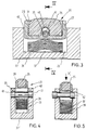
- Figures 1 to 3 there is also a carriage below 1 designated Kluppenwagen shown along one rectangular in cross section in the exemplary embodiment shown Track 3, which is cut out on a side shown carrier 5 is held and anchored, move becomes.
- the carriages 1 are known to comprise e.g. a clip table 7, on which by means of a movable Clip lever 9 the edge of a film web 11 to be stretched can be recorded and recorded.
- the exemplary embodiment explained relates to carriages 1 with clips, such as B. for a simultaneous plastic film stretching system be used.
- the individual carriages 1 are not in the illustrated embodiment connected to each other via a chain lever mechanism, over which the tenter spacing is set, but will be in contrast z. B. by means of a linear motor drive on their orbit along the track 3 with changing Distance controlled to a neighboring carriage driven.
- the carriage 1 include horizontal and vertical rollers 13, over which they along the rail 3rd roll and be moved.
- the damper device two-stage structure with a first shock absorber device 21 and with a second shock absorber device 23 includes.
- the first shock absorber device 21 has an elastomer insert 25 on that in a pot-shaped insert-receiving part 27 is arranged.
- the elastomer insert 25 protrudes the edge 29 of the cup-shaped insert-receiving part 27 over, with the edge 29 a subsequent one also marked with the reference number 29 forms (whose meaning will be discussed later becomes).
- the shape of the elastomer insert 25 is such that between the inner wall of the pot-shaped insert-receiving part 27 at least adjacent to its edge 29 and the adjacent wall of the elastomer insert 25 in unloaded state free receiving space 31 is formed, in which the preferably volume-deformable elastomer element in the event of a collision with an adjacent one Carriage can be deformed into it.
- the cup-shaped insert-receiving part 27 (which in plan view not only round, but z. B. also square or shaped rectangular or different can be) by means of a retaining bolt 35 in a corresponding Immersing receiving space 37 and out of it housed above.
- the second shock absorber device in the receiving space 37 23 provided, which preferably consists of a leaf spring assembly 39, which is located on the floor 37 'of the receiving space supports and the underside of the cup-shaped insert-receiving part 27 already in the unloaded initial state pressurized and above it the cup-shaped Insert receiving part 27 in that shown in Figures 3 and 4 tee-off limited starting position presses. In this starting position is the cup-shaped insert receiving part 27 pressed against the stop formed by the retaining bolt 35.
- the insert receiving part 27 has a cross section in FIG Pear-shaped, i.e. in the direction extending from the leaf spring package 39 with extended Backdrop 40 formed bore.
- the retaining bolt 35 points at its opposite end faces a collar 41 with a larger outer diameter than in his Middle section, with the outer diameter of the federal government 41 less than or equal to the enlarged bore cross section 40 is.
- the pot-shaped insert-receiving part is used for assembly 27 against the force of the leaf spring assembly 39 in the Receiving space 37 pressed in carriage 1 in the direction of arrow K, until the leaf springs 39 are plane-parallel to the floor 37 ' lie. In this position shown in Figure 5 can then the retaining bolt 35 through the enlarged bore cross section 40 can be inserted.
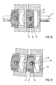
- Figure 7 shows the situation in which a trailing Carriage 1 drives onto a carriage 1 traveling in front, the elastomer insert 25 compressing or is volume-deformed until the edge forming a stop 29 of the cup-shaped insert receiving part 27 on the rear Baffle surface 47 of the leading carriage 1 strikes. It is the first of the two-tier Damping effect, what about bumps in comparison low differential speed between two Carriages can be reversibly picked up and damped.
- the elastomer insert 25 is already pressed completely into the cup-shaped insert receiving part 27 at a force F 1max , so that when the edge 29 then stops against the rear impact surface 47 of a carriage 1 traveling in front, one further deformation of the elastomer insert 25 is prevented.
- the maximum force F 1max required for this is significantly lower than the feed force in the stack zone upstream of the stretching zone.
- the exact clip division KT indicated in FIG. 7, ie the exact distance from clip to clip in the stack zone, is always reproducibly maintained.
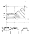
- the second shock absorber device 23 acts at higher run-up forces . However, this absorbs the higher run-up forces only when a minimum force F 2min is exceeded (FIG. 10).
- the springs of the energy accumulator 39 are thus designed with such a high preload that the feed forces present in the stack zone are always safely and clearly below the preload force F 2min and thus prevent the pot-shaped insert-receiving part 27 from shifting against the force of the leaf spring package 39 .
- the "jump in force" ⁇ F at the end of the effective range of the first shock absorber device 21 and before the second shock absorber device 23 begins to take effect is therefore, according to the illustration in FIG. 10, significantly greater than the feed forces occurring in the stack area between the carriages the exact clip division KT in the stack area can be clearly and reproducibly set before the stretching zone begins.
- the force range ⁇ VK is also shown in FIG. 10, which is the lower and upper limit of the Stack area occurring feed forces VK describes.
- the two shock absorber devices 21 and 23 work springy, especially reversible springy. You can do it also have a dampening effect, i.e. Energy, i.e. absorbing impact energy and at least in part through energy conversion (e.g. heat etc.).
- a dampening effect i.e. Energy, i.e. absorbing impact energy and at least in part through energy conversion (e.g. heat etc.).
- the damping in the shock absorber device 21 due to internal friction in the elastomer insert 25 reached.
- the damping due to the friction between the individual leaf springs of the leaf spring assembly 39 accomplished.
- the damping energy is indicated in the diagram according to FIG. 10. She corresponds to the area by the solid Line (compression of the shock absorber concerned) and the dashed line (extension of the concerned Shock absorber device) is included.
- the characteristic curve of the shock absorber device 23 runs with a comparatively constant and greater gradient up to a maximum force F 2max , at which the leaf spring assembly 39 is fully pressed and the lowest leaf spring on the floor 37 'of the receiving space 37 is present.
- a third shock absorber device could then become active, which is made possible, for example, by the structure of the clip structure.
- the receiving space 37 of the second shock absorber device 23 can be designed to be at least slightly resilient with respect to the remaining part of the carriage 1, due to the structure of the coupling, in order to absorb even higher impact forces.
- This so-called third shock absorber device can be designed such that it only becomes effective after the force F 2max has been reached , that is to say at the end of the effective range of the second shock absorber device . Deviating from this, however, it can already be effective with forces which are at least slightly below the force F 2max .
- the shock absorption in this third shock absorber area should preferably be reversible and - if possible - even damping.
Landscapes
- Engineering & Computer Science (AREA)
- Mechanical Engineering (AREA)
- General Engineering & Computer Science (AREA)
- Vibration Dampers (AREA)
- Shaping By String And By Release Of Stress In Plastics And The Like (AREA)
Abstract
Description
- ein exakter, reproduzierbarer Abstand der Kluppen beim Einführen der Folie (in diesem Bereich - dem sogenannten Stack - sind die Kluppenwagen auf Stoß zusammengefahren); und
- eine Kraftübertragung von Kluppe zu Kluppe, d.h. zum Antrieb und zur Vorschubbewegung der einzelnen Lauf-bzw. Kluppenwagen (die Vortriebs- und Rückhaltekräfte dürfen den Kluppenabstand bis hin zum Beginn der Streckzone nicht verändern).
- Bei normalem Betriebszustand stoßen die Kluppen mit geringer Differenzgeschwindigkeit aufeinander, z.B. bei der sogenannten Stack-Bildung (vor der Reckzone). Dabei belasten die harten metallischen Stöße zwischen den Kluppen sowohl die Laufrollen der Kluppenwägen wie aber auch die Schienen selbst. Selbst Kluppen mit großen Elastomerdämpfern können, aufgrund des stets vorhandenen Mißverhältnisses von Antriebskraft und unterschiedlichen Reibungsverlusten, die harten Stöße nicht ganz vermeiden.
- Bei Betriebsstörungen bzw. bei sich mit der Lebensdauer ungleichmäßig veränderndem Laufverhalten der Kluppen im Rücklauf können Kollisionen mit teilweise extremen Differenzgeschwindigkeiten auftreten, die zu erheblichen Schäden an Laufrollen, Schienen sowie der Kluppenstruktur selbst führen. Zumindest wird dadurch das feste Anschlagteil plastisch verformt, wodurch die Kluppenteilung (d.h. der exakte Abstand von Kluppe zu Kluppe im sog. Stack vor der Reckzone) verloren geht. Ein dadurch bedingter und sich auch nur geringfügig ändernder Abstand zwischen den Kluppen in dem sogenannten Sammelbereich (Stack-Bereich) vor der Reckzone führt dann aber, aufgrund des dadurch bedingten unerwünschten sich verändernden Reckverhältnisses, zu einer entsprechenden nachteiligen Beeinträchtigung bei der durch Reckung herzustellenden Kunststoffolienbahn.
- Ein weiches Abfangen von Lauf- oder Kluppenwagen, die mit geringer Differenzgeschwindigkeit aufeinander auflaufen. Dabei wird eine reversible Verformung unter diesen normalen Betriebsbedingungen bevorzugt, um ohne weitere technische Maßnahmen einen möglichst langen Dauerbetrieb zu gewährleisten.
- Auch bei großen Differenzgeschwindigkeiten wird eine Aufnahme hoher dynamischer Energien ohne jede Beschädigung der Laufrollen, der Schiene oder Kluppen, d.h. also der Lauf- oder Kluppenwagen überhaupt gewährleistet, und dies ebenfalls bevorzugt wieder im Sinne einer reversiblen Aufnahme dieser dynamischen Kräfte und Energien.
- Aber auch bei hohen Differenzgeschwindigkeiten kann neben der Stoßdämpfung durch die Energieaufnahme durch die Federeinrichtungen (einer ersten sowie einer zweiten Stoßdämpfereinrichtung) zudem eine Dämpfung des Stoßes zusätzlich durch Energieumformung realisiert werden.
- Vor der unmittelbaren Reckzone (Stack) läßt sich durch die Begrenzung der Federkraft des Dämpfers auf eine maximale Dämpfkraft die gewünschte exakte Kluppenteilung, d.h. ein exakt gleichbleibender Abstand von Kluppe zu Kluppe vor der Reckzone reproduzierbar einhalten.
- In einer bevorzugten Ausführungsform der Erfindung ist ebenfalls gewährleistet, daß die Stoßdämpfervorrichtung auch in Kurven und Umkehrungen gleichsam wirksam ist.
- Selbst bei routinemäßiger Wartung oder im Reparaturfall überhaupt erlaubt die erfindungsgemäße Stoßdämpfervorrichtung eine leichte Austauschbarkeit der bei der Kollision eventuell in Mitleidenschaft gezogenen Prallteile.
- Figur 1 :
- einen längs einer Laufschiene verfahrbaren Laufwagen in Parallelansicht zur Laufschiene;
- Figur 2 :
- eine Draufsicht auf zwei längs einer Laufschiene im Abstand zueinander verfahrbare Laufwagen;
- Figur 3 :
- eine vergrößerte Detaildarstellung der Stoßdämpfervorrichtung an einem Laufwagen;
- Figur 4 :
- eine Schnittdarstellung längs der Linie IV - IV in Figur 3;
- Figur 5 :
- eine zu Figur 4 entsprechende Darstellung zur Erläuterung der Montage der erfindungsgemäßen Stoßdämpfervorrichtung;
- Figur 6 :
- eine schematische Schnittdarstellung durch zwei Stoßdämpfervorrichtungen an zwei nicht aufgelaufenen Laufwagen;
- Figur 7 :
- eine zu Figur 6 entsprechende Darstellung, bei der der nachlaufende Laufwagen auf einen vorausgehenden Laufwagen unter Aktivierung der ersten Stoßdämpfereinrichtung aufgelaufen ist;
- Figur 8 :
- eine zu Figur 6 und 7 entsprechende Darstellung der Stoßdämpfereinrichtung, bei der auch die zweite vorgesehene Stoßdämpfereinrichtung maximal verformt ist;
- Figur 9 :
- eine Darstellung zur Erläuterung der Funktionsweise der erfindungsgemäßen Stoßdämpfervorrichtung in Kurven und Umkehrungen; und
- Figur 10 :
- ein Diagramm mit drei Zustandsdarstellungen zur Erläuterung der Feder-DämpferKennlinie (die Darstellung zeigt die Federkraft F gegenüber dem Federweg FW in mm).
- die erste Stoßdämpfer-Einrichtung 21 weist einen Elastomereinsatz 25 auf, der über einen einen Anschlag 29 bildenden Rand eines Einsatz-Aufnahmeteiles 27 übersteht, wobei der Elastomereinsatz 25 bei Überschreiten einer Grenzkraft F1max bis auf die Ebene des Anschlags 29 komprimiert und/oder volumenverformt wird,
- die zweite Stoßdämpfer-Einrichtung 23 besteht aus einer Druckfedereinrichtung 39, die erst nach Überschreiten der Auslöse-Grenzkraft F2min aktivierbar ist, und
- die erste und zweite Stoßdämpfer-Einrichtung 21, 23 sind so aufgebaut, daß ein Kraftsprung ΔF zwischen der Grenzkraft F1max am Ende des Wirksamkeitsbereiches der ersten - Stoßdämpfer-Einrichtung 21 und der Auslöse-Grenzkraft F2min am Beginn des Wirksamwerdens der zweiten Stoßdämpfer-Einrichtung 23 vorhanden ist, der der exakten Anlage und damit einem definierten Abstand der Laufwagen 1 dient, die die Stoßdämpfervorrichtung im Normalbetrieb in einem Kraftbereich ΔVK oberhalb der Grenzkraft F1max und unterhalb der Auslöse-Grenzkraft F2min belasten.
Claims (13)
- Stoßdämpfervorrichtung für Laufwagen (1), insbesondere für eine simultane Reckanlage, mit einem zumindest zweistufigen Dämpferaufbau unter Verwendung einer ersten und zweiten Stoßdämpfer-Einrichtung (21, 23), wobei die zweite Stoßdämpfer-Einrichtung (23) erst nach Überschreiten einer Auslöse-Grenzkraft aktivierbar ist, gekennzeichnet durch die folgenden weiteren Merkmaleder Feder-Kennlinien-Verlauf der ersten und zweiten Stoßdämpfer-Einrichtung (21, 23) erfolgt nach Art einer Sprungfunktion derart, daß der minimale Grenz-Auslösewert (F2min), bei welcher die zweite Stoßdämpfer-Einrichtung (23) aktiverbar ist, um einen Kraft-Differenzwert (ΔF) oberhalb des Kraft-Begrenzungswertes (F1max) liegt, bei welchem die erste Stoßdämpfer-Einrichtung (21) bei Erreichen ihres maximalen Stoßdämpfungswertes deaktiviert ist, unddie Vorschubkraft (VK), mittels der die Laufwagen (1) in einem Vorschubbereich (Stack-Bereich) unter Ausübung von Vorschubkräften vorwärts bewegt werden, ist größer als der Grenzkraftwert (F1max) am Ende des Wirksamkeitsbereiches der ersten Stoßdämpfer-Einrichtung (21) und kleiner als der Grenzkraftwert (F2min) am Beginn des Wirksamkeitsbereiches der zweiten Stoßdämpfer-Einrichtung (23).
- Stoßdämpfervorrichtung nach Anspruch 1, dadurch gekennzeichnet, daß auch die zweite Stoßdämpfer-Einrichtung (23) in ihrem Funktionsbereich reversibel arbeitet.
- Stoßdämpfervorrichtung nach Anspruch 1 oder 2, dadurch gekennzeichnet, daß die erste und/oder die zweite Stoßdämpfer-Einrichtung (21, 23) energieumformende Dämpfungselemente umfassen.
- Stoßdämpfervorrichtung nach einem der Ansprüche 1 bis 3, dadurch gekennzeichnet, daß zumindets eine der beiden Stoßdämpfer-Einrichtungen (21, 23) relativ zu der anderen Stoßdämpfer-Einrichtung (23, 21) kippbar ist.
- Stoßdämpfervorrichtung nach Anspruch 4, dadurch gekennzeichnet, daß die erste Stoßdämpfer-Einrichtung (21) um einen Haltebolzen (35) in Richtung eines gekrümmten Bahnverlaufes gegenüber der zweiten Stoßdämpfer-Einrichtung (23) zumindest geringfügig kippbar ist.
- Stoßdämpfervorrichtung nach einem der Ansprüche 1 bis 5, dadurch gekennzeichnet, daß die erste Stoßdämpfer-Einrichtung (21) einen Elastomereinsatz (25) aufweist, der über einen einen Anschlag (29) bildenden Rand eines Einsatz-Aufnahmeteiles (27) übersteht, wobei der Elastomereinsatz (25) bei Überschreiten der Grenzkraft (F1max) bis auf die Ebene des Anschlages (29) komprimiert und/oder volumenverformt ist.
- Stoßdämpfervorrichtung nach einem der Ansprüche 1 bis 6, dadurch gekennzeichnet, daß die zweite Stoßdämpfer-Einrichtung (23) aus einem Blattfederpaket (39) besteht.
- Stoßdämpfervorrichtung nach Anspruch 7, dadurch gekennzeichnet, daß der konvex vorstehende Abschnitt des Blattfederpaketes (39) an der Unterseite der ersten Stoßdämpfer-Einrichtung (21) anliegt, und zwar vorzugsweise in dessem mittleren Bereich.
- Stoßdämpfervorrichtung nach Anspruch 7 oder 8, dadurch gekennzeichnet, daß in kollisionsfreiem Zustand des Laufwagens (1) durch die zweite Stoßdämpfer-Einrichtung (23) Rückstellkräfte auf die erste Stoßdämpfer-Einrichtung (21) dergestalt einwirken, daß die erste, zumindest geringfügig verkippbare Stoßdämpfer-Einrichtung (21) in ihre neutrale in Geradeausrichtung ausgerichtete Ausgangslage verschwenkt gehalten ist.
- Stoßdämpfervorrichtung nach einem der Ansprüche 1 bis 9, dadurch gekennzeichnet, daß die erste Stoßdämpfereinrichtung (21) eine Bohrung (40) aufweist, die durch einen, eine Kippachse zum Verkippen der ersten gegenüber der zweiten Stoßdämpfer-Einrichtung (21, 23) erlaubenden Haltebolzen (35) durchragt wird, wobei die Bohrung (40) in Querrichtung quer zur Kippachse in Richtung der Vorspannkräfte der zweiten Stoßdämpfer-Einrichtung (23) mit einem erweiterten Bohrungsabschnitt zur Ermöglichung einer Relativverschiebung der ersten Stoßdämpfer-Einrichtung (21) gegenüber der zweiten Stoßdämpfer-Einrichtung (23) versehen ist.
- Stoßdämpfervorrichtung nach Anspruch 10, dadurch gekennzeichnet, daß der erweiterte Bohrungsabschnitt der Bohrung (40) im Querschnitt birnenförmig erweitert ist, so daß bei entgegen der Kraft der zweiten Stoßdämpfer-Einrichtung (23) verschobener erster Stoßdämpfer-Einrichtung (21) ein Haltebolzen durch die Bohrung (40) hindurchsteckbar ist, der stirnseitig mit einem überstehenden Bund versehen ist, dessen Außendurchmesser gleich oder kleiner dem erweiterten Bohrungsabschnitt (40) und größer als der demgegenüber mit geringerem Durchmesser versehene Bohrungsabschnitt der Bohrung (40) versehen ist.
- Stoßdämpfervorrichtung nach einem der Ansprüche 1 bis 11, dadurch gekennzeichnet, daß zumindest eine dritte Stoßdämpfer-Einrichtung vorgesehen ist, die vorzugsweise durch die Laufwagenstruktur gebildet ist.
- Stoßdämpfervorrichtung nach Anspruch 12, dadurch gekennzeichnet, daß auch die zumindest dritte Stoßdämpfer-Einrichtung zumindest in einem Belastungsbereich reversibel arbeitet und vorzugsweise stoßdämpfend wirkt.
Applications Claiming Priority (3)
| Application Number | Priority Date | Filing Date | Title |
|---|---|---|---|
| DE4441020A DE4441020C1 (de) | 1994-11-17 | 1994-11-17 | Stoßdämpfervorrichtung für Laufwagen insbesondere für Folienreckanlagen |
| DE4441020 | 1994-11-17 | ||
| PCT/EP1995/004379 WO1996016278A1 (de) | 1994-11-17 | 1995-11-07 | Stossdämpfervorrichtung für laufwagen insbesondere für folienreckanlagen |
Publications (2)
| Publication Number | Publication Date |
|---|---|
| EP0736148A1 EP0736148A1 (de) | 1996-10-09 |
| EP0736148B1 true EP0736148B1 (de) | 1998-06-03 |
Family
ID=6533526
Family Applications (1)
| Application Number | Title | Priority Date | Filing Date |
|---|---|---|---|
| EP95937878A Expired - Lifetime EP0736148B1 (de) | 1994-11-17 | 1995-11-07 | Stossdämpfervorrichtung für laufwagen insbesondere für folienreckanlagen |
Country Status (6)
| Country | Link |
|---|---|
| US (1) | US5743516A (de) |
| EP (1) | EP0736148B1 (de) |
| JP (1) | JP3998263B2 (de) |
| KR (1) | KR970700829A (de) |
| DE (2) | DE4441020C1 (de) |
| WO (1) | WO1996016278A1 (de) |
Families Citing this family (8)
| Publication number | Priority date | Publication date | Assignee | Title |
|---|---|---|---|---|
| TW425045U (en) * | 1999-08-27 | 2001-03-01 | Umax Data Systems Inc | Vibration inhibition mechanism of scanner |
| CN101920877B (zh) * | 2010-08-27 | 2012-09-12 | 康力电梯股份有限公司 | 一种钢丝绳减震板 |
| DE102013011965A1 (de) | 2013-07-18 | 2015-01-22 | Brückner Maschinenbau GmbH & Co. KG | Linearmotorgetriebene Transportanlage, insbesondere Reckanlage |
| DE102013017011A1 (de) | 2013-10-14 | 2015-04-30 | Brückner Maschinenbau GmbH & Co. KG | Kluppen-Transporteinheit |
| DE102014011513A1 (de) | 2014-07-31 | 2016-02-04 | Brückner Maschinenbau GmbH & Co. KG | Kluppe mit Kniehebel-Anordnung |
| DE102014013901A1 (de) | 2014-09-18 | 2016-03-24 | Brückner Maschinenbau GmbH & Co. KG | Linearmotorangetriebene Simultan-Reckanlage |
| CN107718608A (zh) * | 2017-07-17 | 2018-02-23 | 泉州嘉德利电子材料有限公司 | 一种耐高温电容器用聚丙烯薄膜的制备方法 |
| DE102021119557A1 (de) | 2021-07-28 | 2023-02-02 | Brückner Maschinenbau GmbH & Co. KG | Einführeinrichtung zum automatischen Einführen einer Materialbahn in eine Reckanlage, Anlage sowie Verfahren |
Family Cites Families (21)
| Publication number | Priority date | Publication date | Assignee | Title |
|---|---|---|---|---|
| BE446506A (de) * | 1940-04-01 | |||
| US2557610A (en) * | 1947-05-24 | 1951-06-19 | Ohio Rubber Co | Resilient mounting |
| US2661943A (en) * | 1951-02-15 | 1953-12-08 | Flexible Metals Corp | Resilient cushioning device |
| US2889056A (en) * | 1955-01-11 | 1959-06-02 | Symington Wayne Corp | Rubber cushioning unit |
| FR1151730A (fr) * | 1955-11-28 | 1958-02-05 | Phoenix Gummiwerke Ag | Bourrelet |
| FR1363297A (fr) * | 1963-04-29 | 1964-06-12 | Domange Ets | Perfectionnements aux butées à grande capacité d'énergie |
| PL123472B1 (en) * | 1977-05-10 | 1982-10-30 | Inst Chemii Przemyslowej | Apparatus for absorbing mechanical energy in particular very strong impact energy |
| IT1172886B (it) * | 1978-04-07 | 1987-06-18 | Fata Spa Ora Fata Europ Group | Dispositivo di trasporto aereo monorotaia |
| JPS5950240A (ja) * | 1982-09-13 | 1984-03-23 | Nissan Motor Co Ltd | パワ−ユニツト支持装置 |
| US4830347A (en) * | 1983-05-23 | 1989-05-16 | Marathon Oil Company | Assembly for and a method of absorbing impact shock loads |
| DE3425802A1 (de) * | 1984-07-13 | 1986-01-23 | P+S Plast- und Schaumtechnik GmbH & Co KG, 2840 Diepholz | Zellkunststoff-puffer |
| US4853602A (en) * | 1985-12-24 | 1989-08-01 | E. I. Dupont De Nemours And Company | System for using synchronous secondaries of a linear motor to biaxially draw plastic films |
| US4675582A (en) * | 1985-12-24 | 1987-06-23 | E. I. Du Pont De Nemours And Company | System useful for controlling multiple synchronous secondaries of a linear motor along an elongated path |
| US4825111A (en) * | 1987-11-02 | 1989-04-25 | E. I. Du Pont De Nemours And Company | Linear motor propulsion system |
| US5072493A (en) * | 1988-06-22 | 1991-12-17 | E. I. Du Pont De Nemours And Company | Apparatus for drawing plastic film in a tenter frame |
| US5051225A (en) * | 1988-06-22 | 1991-09-24 | E. I. Du Pont De Nemours And Company | Method of drawing plastic film in a tenter frame |
| DE3909494A1 (de) * | 1989-03-22 | 1990-09-27 | Hartmut Eichinger | Endlagendaempfungssystem |
| FR2681926A1 (fr) * | 1991-10-01 | 1993-04-02 | Hutchinson | Dispositif de suspension a lames flechissantes a grand debattement. |
| DE9211550U1 (de) * | 1991-11-29 | 1993-04-01 | Paul Oberholz + Söhne Schloß- und Beschlagfabrik GmbH, 5620 Velbert | Puffer zur Abstützung von Klappen o.dgl., insbesondere Kraftfahrzeug-Kofferraumklappen |
| US5257680A (en) * | 1991-12-20 | 1993-11-02 | Lord Corporation | Surface effect dampers having both hysteresis and a frictional component |
| US5285889A (en) * | 1992-11-16 | 1994-02-15 | Jervis B. Webb Company | Attachment member for conveyor chain and trolley assembly |
-
1994
- 1994-11-17 DE DE4441020A patent/DE4441020C1/de not_active Expired - Fee Related
-
1995
- 1995-11-07 EP EP95937878A patent/EP0736148B1/de not_active Expired - Lifetime
- 1995-11-07 JP JP51650296A patent/JP3998263B2/ja not_active Expired - Fee Related
- 1995-11-07 US US08/669,422 patent/US5743516A/en not_active Expired - Lifetime
- 1995-11-07 DE DE59502407T patent/DE59502407D1/de not_active Expired - Lifetime
- 1995-11-07 WO PCT/EP1995/004379 patent/WO1996016278A1/de not_active Ceased
-
1996
- 1996-07-16 KR KR1019960703833A patent/KR970700829A/ko not_active Withdrawn
Also Published As
| Publication number | Publication date |
|---|---|
| US5743516A (en) | 1998-04-28 |
| WO1996016278A1 (de) | 1996-05-30 |
| JPH09511051A (ja) | 1997-11-04 |
| JP3998263B2 (ja) | 2007-10-24 |
| KR970700829A (ko) | 1997-02-12 |
| EP0736148A1 (de) | 1996-10-09 |
| DE4441020C1 (de) | 1996-05-23 |
| DE59502407D1 (de) | 1998-07-09 |
Similar Documents
| Publication | Publication Date | Title |
|---|---|---|
| DE4310757B4 (de) | Objekt-Haltevorrichtung | |
| DE102014108577B3 (de) | Lenksäule für ein Kraftfahrzeug | |
| EP1275535B1 (de) | Getriebe, insbesondere für eine Stabilisatoranordnung für ein Kfz-Fahrwerk | |
| DE19540914C2 (de) | Stromabnehmer für die Energieübertragung zwischen einem Fahrdraht und einem Triebwagen | |
| WO2016096528A1 (de) | Deformationsstruktur, insbesondere zum fussgängerschutz für ein kraftfahrzeug | |
| EP3079526B1 (de) | Führungsvorrichtung für linear bewegbare bauteile | |
| WO2014032068A1 (de) | Schwenkschiebetürmodul für ein schienenfahrzeug | |
| DE19540913C1 (de) | Stromabnehmer für die Energieübertragung zwischen einem Fahrdraht und einem Triebwagen | |
| DE4441020C1 (de) | Stoßdämpfervorrichtung für Laufwagen insbesondere für Folienreckanlagen | |
| DE3003996A1 (de) | Stabilisierungs-vorrichtung fuer wagen von schwebebahnen | |
| DE10109557B4 (de) | Verbesserter Pufferträger und -lager | |
| DE10008523B4 (de) | System zur kontinuierlichen Energieaufnahme durch Relativverschiebung | |
| WO2014180672A1 (de) | Karosserieträger für ein kraftfahrzeug | |
| DE112019005901T5 (de) | Bewegungsführungsvorrichtung | |
| EP3170715B1 (de) | Schiebetürmodul/schwenkschiebetürmodul für ein schienenfahrzeug | |
| DE4401874C1 (de) | Dämpfungselement | |
| DE19757917A1 (de) | Eisenbahnfahrzeug mit Pufferbohle, die befähigt ist, sich kontrolliert zu verformen, wenn sie einem relevanten Druck ausgesetzt wird | |
| EP0858937A2 (de) | Überstoss-Energieverzehreinrichtung für Schienenfahrzeuge | |
| DE3328290C2 (de) | ||
| DE2453223A1 (de) | Gleisbremsprellbock fuer hohe auflaufgeschwindigkeiten | |
| DE3231327A1 (de) | Stossdaempfer fuer in fahrzeugen transportierte lasten | |
| EP3771609A1 (de) | Hülsenpuffer mit abschnittsweise ummanteltem stössel | |
| DE102005021741B4 (de) | Vorrichtung zur Energieabsorption bei einer Energieeinwirkung auf ein Kraftfahrzeug | |
| DE19881900B4 (de) | Gleisbremseinrichtung | |
| EP2829451B1 (de) | Führungssystem für eine Schwenkschiebetür eines Schienenfahrzeugs |
Legal Events
| Date | Code | Title | Description |
|---|---|---|---|
| PUAI | Public reference made under article 153(3) epc to a published international application that has entered the european phase |
Free format text: ORIGINAL CODE: 0009012 |
|
| 17P | Request for examination filed |
Effective date: 19960814 |
|
| AK | Designated contracting states |
Kind code of ref document: A1 Designated state(s): BE CH DE FR GB IT LI |
|
| GRAG | Despatch of communication of intention to grant |
Free format text: ORIGINAL CODE: EPIDOS AGRA |
|
| 17Q | First examination report despatched |
Effective date: 19970829 |
|
| GRAG | Despatch of communication of intention to grant |
Free format text: ORIGINAL CODE: EPIDOS AGRA |
|
| GRAH | Despatch of communication of intention to grant a patent |
Free format text: ORIGINAL CODE: EPIDOS IGRA |
|
| GRAH | Despatch of communication of intention to grant a patent |
Free format text: ORIGINAL CODE: EPIDOS IGRA |
|
| GRAA | (expected) grant |
Free format text: ORIGINAL CODE: 0009210 |
|
| AK | Designated contracting states |
Kind code of ref document: B1 Designated state(s): BE CH DE FR GB IT LI |
|
| REG | Reference to a national code |
Ref country code: CH Ref legal event code: EP |
|
| GBT | Gb: translation of ep patent filed (gb section 77(6)(a)/1977) |
Effective date: 19980604 |
|
| REF | Corresponds to: |
Ref document number: 59502407 Country of ref document: DE Date of ref document: 19980709 |
|
| REG | Reference to a national code |
Ref country code: CH Ref legal event code: NV Representative=s name: SCHMAUDER & WANN PATENTANWALTSBUERO, INHABER KLAUS |
|
| ITF | It: translation for a ep patent filed | ||
| ET | Fr: translation filed | ||
| PLBE | No opposition filed within time limit |
Free format text: ORIGINAL CODE: 0009261 |
|
| STAA | Information on the status of an ep patent application or granted ep patent |
Free format text: STATUS: NO OPPOSITION FILED WITHIN TIME LIMIT |
|
| 26N | No opposition filed | ||
| PGFP | Annual fee paid to national office [announced via postgrant information from national office to epo] |
Ref country code: GB Payment date: 20011025 Year of fee payment: 7 |
|
| PGFP | Annual fee paid to national office [announced via postgrant information from national office to epo] |
Ref country code: BE Payment date: 20011123 Year of fee payment: 7 |
|
| PGFP | Annual fee paid to national office [announced via postgrant information from national office to epo] |
Ref country code: CH Payment date: 20011126 Year of fee payment: 7 |
|
| REG | Reference to a national code |
Ref country code: GB Ref legal event code: IF02 |
|
| PG25 | Lapsed in a contracting state [announced via postgrant information from national office to epo] |
Ref country code: GB Free format text: LAPSE BECAUSE OF NON-PAYMENT OF DUE FEES Effective date: 20021107 |
|
| PG25 | Lapsed in a contracting state [announced via postgrant information from national office to epo] |
Ref country code: LI Free format text: LAPSE BECAUSE OF NON-PAYMENT OF DUE FEES Effective date: 20021130 Ref country code: CH Free format text: LAPSE BECAUSE OF NON-PAYMENT OF DUE FEES Effective date: 20021130 Ref country code: BE Free format text: LAPSE BECAUSE OF NON-PAYMENT OF DUE FEES Effective date: 20021130 |
|
| BERE | Be: lapsed |
Owner name: *BRUCKNER MASCHINENBAU G.M.B.H. Effective date: 20021130 |
|
| GBPC | Gb: european patent ceased through non-payment of renewal fee | ||
| REG | Reference to a national code |
Ref country code: CH Ref legal event code: PL |
|
| PG25 | Lapsed in a contracting state [announced via postgrant information from national office to epo] |
Ref country code: IT Free format text: LAPSE BECAUSE OF NON-PAYMENT OF DUE FEES Effective date: 20051107 |
|
| PGFP | Annual fee paid to national office [announced via postgrant information from national office to epo] |
Ref country code: DE Payment date: 20141120 Year of fee payment: 20 |
|
| PGFP | Annual fee paid to national office [announced via postgrant information from national office to epo] |
Ref country code: FR Payment date: 20141118 Year of fee payment: 20 |
|
| REG | Reference to a national code |
Ref country code: DE Ref legal event code: R071 Ref document number: 59502407 Country of ref document: DE |