EP0735233B1 - Hydraulisch betätigtes Muffenventil für Erdbohrungen - Google Patents
Hydraulisch betätigtes Muffenventil für Erdbohrungen Download PDFInfo
- Publication number
- EP0735233B1 EP0735233B1 EP96104393A EP96104393A EP0735233B1 EP 0735233 B1 EP0735233 B1 EP 0735233B1 EP 96104393 A EP96104393 A EP 96104393A EP 96104393 A EP96104393 A EP 96104393A EP 0735233 B1 EP0735233 B1 EP 0735233B1
- Authority
- EP
- European Patent Office
- Prior art keywords
- hydraulic
- sliding sleeve
- piston
- outer body
- seals
- Prior art date
- Legal status (The legal status is an assumption and is not a legal conclusion. Google has not performed a legal analysis and makes no representation as to the accuracy of the status listed.)
- Expired - Lifetime
Links
Images


Classifications
-
- E—FIXED CONSTRUCTIONS
- E21—EARTH OR ROCK DRILLING; MINING
- E21B—EARTH OR ROCK DRILLING; OBTAINING OIL, GAS, WATER, SOLUBLE OR MELTABLE MATERIALS OR A SLURRY OF MINERALS FROM WELLS
- E21B34/00—Valve arrangements for boreholes or wells
- E21B34/06—Valve arrangements for boreholes or wells in wells
- E21B34/10—Valve arrangements for boreholes or wells in wells operated by control fluid supplied from outside the borehole
Definitions
- the invention relates to a sliding sleeve for installation in a pipe tour Bore according to the preamble of claim 1.
- Sliding sleeves are part of the underground equipment of packers Probe and are generally used to create a connection between the interior and outside of the tube tour. By pressing the sliding sleeve hydraulic communication between the riser and the annulus one Drilling enables or prevents. In normal, with packers equipped bores, the function of a sliding sleeve is limited to that Circulating and circulating the dead pump liquid when performing Completion or workover tasks.
- the individual carriers are perforated one after the other and then, if necessary, separated by packers. Should be two or several intersected carriers are not jointly promoted in one probe become a sliding sleeve in the interval packed with two packers built-in, which is a temporary opening or closing of the packaged Allow wearer.
- the opening or closing as well as the conversion of the Funding from one carrier to another is carried out by operating this built-in sliding sleeves. These sliding sleeves are made using wireline devices actuated.
- the US 4,842,074 deals with an underground safety valve, which means Hydraulic pressure is brought into an open position against a spring force, the Valve closes after releasing pressure from the same hydraulic line by the spring force of the valve.
- the valve has some features of a conventional sliding sleeve. By Move two concentrically one inside the other and through Cylinders sealed in elastomeric rings become those in the cylinder walls inserted openings pushed apart or one above the other. This The principle applies to all sliding sleeves, whether operated mechanically or otherwise are applied. However, such valves are not suitable for the function of a Sliding sleeve, namely for example the above communication between two institutions from which funding is to be provided separately.
- the invention has for its object to design a sliding sleeve such that they operated in a simple manner and without wireline work can be controlled.
- the hydraulic sliding sleeve consists of an outer body with an integrated Hydraulic unit and a movable hydraulic piston. On the outer body seals are arranged in particular on the hydraulic unit, the Seals especially above and below the circulation openings and attached above and below the cylinder cavity. At the top and lower end of the cylinder cavity are inlets or outlets for a hydraulic fluid supplied through the hydraulic connections. Furthermore gaskets are attached to the hydraulic piston thickening, which the Divide the cylinder cavity into two mutually sealed chambers. Above and below the cylinder cavity and sealed to this are in Outer body and each in the hydraulic piston circulation openings arranged.
- Such a sliding sleeve can advantageously be hydraulically controlled via the liquid pressure be controlled or operated.
- the further advantages achieved with the invention consist in the simple and quick actuation of the hydraulic Sliding sleeve in particular by the operating personnel, for example by means of a Hydraulic hand pump and the reduction in operating costs for the Sliding sleeve operation. It is also advantageous that no special tool for the Operation is required and the use of costly wireline service personnel omitted, since no wireline devices are required.
- Another advantage is the use in probes, which are sometimes also eruptive promote, because in these cases with installed, running pumps from pump to Inflammatory support and vice versa in a simple, cost and time-saving manner can be changed.
- the increased safety by operating the hydraulic is also advantageous Sliding sleeve, since no lock and for the implementation of these measures No more wireline manipulation on the sod is required. This results in an increased operational safety or reduced danger to the environment for example a gas or oil outbreak.
- the total area of the circulation openings of the sliding sleeves is at least 0.5 times, in particular 1.5 times the internal cross-sectional area of the Tubing string. This has the advantage that when circulating e.g. liquids through the circulation openings when the hydraulic sliding sleeve is open without Limitations of the maximum volume flow of the riser can be circulated can.
- the outer surface of the piston unit and the inner surface of the Hydraulic cylinder units are custom-made.
- the advantage of fine machining and hardening of these surfaces lies in the avoidance or reduction of Signs of wear and thus lead to longer downtimes,
- the upper end profile of the piston unit is in the direction of the riser pipe beveled, in particular at an angle of 30 ° to 60 °.
- the connection or Serving different wireline devices are provided.
- the inside diameter of the piston unit is at least the minimum Inner diameter of the riser pipe above the sliding sleeve. This will in advantageously achieved that wireline devices or other units without Restriction in diameter in the deeper areas of a hole below the sliding sleeve can get. A bottleneck is caused by the sliding sleeve avoided.
- the hydraulic connections are each connected to hydraulic lines that run in parallel connected to the pipe tour and to the surface facilities of the wells are arranged.
- the advantage of this design is that the actuation and control the sliding sleeve can be easily accomplished from above ground.
- the hydraulic sliding sleeve is hydraulically balanced Hydraulic system connected. This advantageously ensures that the static pressures above us are balanced below the piston and relatively low actuation pressures must be applied.
- the hydraulic fluid consists in particular of oil or glycol or water or from mixtures of these liquids.
- the use of different Hydraulic fluids has the advantage that a fluid according to the individual borehole requirements can be selected and used.
- the hydraulic sliding sleeve in Figure 1 consists of an outer body 1, which in middle part as hydraulic cylinder unit 2 with several sealing packages 3 is trained.
- the seals 3 are located above the cylinder cavity 14 and above and below the circulation opening 10 in the outer body the sliding sleeve 1.
- the hydraulic cylinder unit 2 is with two connections 7, 8 for the two hydraulic lines.
- the in the hydraulic cylinder unit 2 built-in hydraulic piston 6, is particularly in the area of piston thickening 15 are provided with seals 4 which connect the hydraulic piston unit 6 to the outer body 1 caulk. Due to the piston thickening 15, the cylinder cavity 14 becomes two chambers sealed against each other.
- wiper rings 18 arranged in the outer body 1, which at the Actuation of the sliding sleeve the existing liquid film on the Stripping hydraulic piston unit 6.
- the threads 11 are for the assembly of the hydraulic sliding sleeve necessary and have an internal pressure resistance that is at least that Internal pressure resistance of the riser pipe.
- the hydraulic piston unit 6 contains circulation openings 5, which in their shape and Size, the circulation openings 10 of the outer body of the sliding sleeve 1st correspond.
- the lower stop 19 represents the limitation of the stroke of the Piston unit 6 down and in this example ensures that the lower Connection for the hydraulic line 8 through the piston thickening 15 is not is closed.
- FIG. 2 shows a hydraulic sliding sleeve in the open state.
- the attack 23 represents the limitation of the stroke of the hydraulic piston unit 6
- Circulation opening 5 of the piston unit 6 covers the circulation opening 10 of the Outer body of the sliding sleeve 1.
- the circulation between the outer and The interior of the sliding sleeve is made.
- the lower chamber of the Cylinder cavity 14 has reached its maximum volume.
- the leadership of the Piston unit 6 is by a nose 16 in the outer body of the sliding sleeve 1, which engages in a slot 17 in the hydraulic piston unit 6, accomplished. This prevents the hydraulic piston unit 6 from rotating.
- the sliding sleeve is closed by pressurizing the Hydraulic fluid line 20 and the pushing down of the piston unit 6 Simultaneously drain liquid from the lower chamber through the lower one Connection 8 and the hydraulic line obtained above ground.
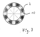
- Figure 3 shows an example of the milled in the hydraulic cylinder unit 2 Circulation openings 10.
- FIG 4 shows the installation of a hydraulic sliding sleeve 29 shown in a riser pipe 27.
- the sliding sleeve is over the Hydraulic fluid lines 20, 28 operated from above.
- the riser pipe string 27 is installed in the annular space 26 of the casing 25.
- the connection between The cement jacket 24 produces casing 25 and rock.
- With the packer 30 is the lower part of the borehole with the perforation 31 of the casing 25 and the Cement jacket 24 is sealed off from the rest of the annular space 26.
- Hydraulic cylinder unit 2 arranged below the circulation openings 10.
Landscapes
- Life Sciences & Earth Sciences (AREA)
- Engineering & Computer Science (AREA)
- Geology (AREA)
- Mining & Mineral Resources (AREA)
- Physics & Mathematics (AREA)
- Environmental & Geological Engineering (AREA)
- Fluid Mechanics (AREA)
- General Life Sciences & Earth Sciences (AREA)
- Geochemistry & Mineralogy (AREA)
- Earth Drilling (AREA)
- Multiple-Way Valves (AREA)
- Consolidation Of Soil By Introduction Of Solidifying Substances Into Soil (AREA)
Description
- 1
- Außenkörper der Schiebemuffe
- 2
- Hydraulikzylindereinheit
- 3
- Dichtungen in 1
- 4
- Dichtungen in 6
- 5
- Zirkulationsöffnungen der Kolbeneinheit 6
- 6
- Hydraulikkolbeneinheit
- 7
- Oberer Anschluß der Hydraulikleitung 20
- 8
- Unterer Anschluß der Hydraulikleitung
- 9
- Abschlußprofil
- 10
- Zirkulationsöffnungen der Hydraulikzylindereinheit
- 11
- Gewinde
- 12
- Oberer Einlaßbereich der Hydraulikflüssigkeit in den Zylinderhohlraum
- 13
- Unterer Einlaßbereich der Hydraulikflüssigkeit in den Zylinderhohlraum
- 14
- Zylinderhohlraum
- 15
- Kolbenverdickung
- 16
- Verdrehsicherungsnase
- 17
- Verdrehsicherungsschlitz
- 18
- Abstreifring
- 19
- Unterer Anschlag (in 1)
- 20
- Hydraulikflüssigkeitsleitung
- 21
- Gewinde zum Anschluß an das Steigrohr
- 22
- Richtung zum Bohrlochkopf
- 23
- Oberer Anschlag (in 1)
- 24
- Zementmantel
- 25
- Futterrohr (Casing)
- 26
- Ringraum
- 27
- Steigrohrstrang (Tubing)
- 28
- Hydraulikflüssigkeitsleitung
- 29
- Schiebemuffe
- 30
- Packer
- 31
- Perforation (Flow Ports)
Claims (10)
- Schiebemuffe dadurch gekennzeichnet, daß die hydraulische Schiebemuffe aus einem Außenkörper (1) mit integrierter Hydraulikeinheit (2) und einem beweglichen Hydraulikkolben (6) besteht und daß an dem Außenkörper (1) Abdichtungen (3) angeordnet sind, und daß sich am oberen und unteren Ende des Zylinderhohlraumes (14) Einlässe oder Auslässe (12, 13) befinden und daß an der Kolbenverdickung (15) Dichtungen (4) befestigt sind, die den Zylinderhohlraum (14) in zwei gegeneinander abgedichtete Kammern teilen, und daß oberhalb oder unterhalb des Zylinderhohlraumes (14) und zu diesem abgedichtet, im Außenkörper (1) und im Hydraulikkolben (6) jeweils Zirkulationsöffnungen (10, 5), angeordnet sind.
- Vorrichtung nach Anspruch 1, dadurch gekennzeichnet, daß
die Abdichtungen (3) oberhalb und unterhalb der Zirkulationsöffnungen (10) sowie oberhalb und unterhalb des Zylinderhohlraumes (14) befestigt sind. - Vorrichtung nach Anspruch 1, dadurch gekennzeichnet, daß die Gesamtfläche der Zirkulationsöffnungen der Schiebemuffen mindestens das 0,5-fache, vorzugsweise das 1,5-fache der inneren Querschnittsfläche des Steigrohrstranges (27) beträgt.
- Vorrichtung nach Anspruch 1 oder 2, dadurch gekennzeichnet, daß die Außenfläche der Kolbeneinheit (6) sowie die Innenfläche der Hydraulikzylindereinheit (2) gehohnt ausgeführt sind.
- Vorrichtung nach einem oder mehreren der Ansprüche 1 bis 3, dadurch gekennzeichnet, daß das obere Abschlußprofil (9) der Kolbeneinheit (6) in Richtung auf das Steigrohr abgeschrägt, vorzugsweise in einem Winkel von 30° bis 60°, angeordnet ist.
- Vorrichtung nach einem oder mehreren der Ansprüche 1 bis 4, dadurch gekennzeichnet, daß der Innendurchmesser der Kolbeneinheit (6) mindestens dem minimalen Innendurchmesser des Steigrohrstranges(27) oberhalb der Schiebemuffe entspricht.
- Vorrichtung nach einem oder mehreren der Ansprüche 1 bis 5, dadurch gekennzeichnet, daß an der Kolbeneinheit (6) ein Verdrehsicherungsschlitz (17) und an dem Außenkörper (1) eine Verdrehsicherungsnase (16) angeordnet ist.
- Vorrichtung nach einem oder mehreren der Ansprüche 1 bis 6, dadurch gekennzeichnet, daß die Hydraulikanschlüsse (7, 8) jeweils mit Hydraulikleitungen (20, 28) verbunden sind, die parallel zur Rohrtour und mit den Übertageeinrichtungen der Bohrungen verbunden angeordnet sind.
- Vorrichtung nach einem oder mehreren der Ansprüche 1 bis 7, dadurch gekennzeichnet, daß die hydraulische Schiebemuffe mit einem hydraulisch ausgeglichenen Hydrauliksystem verbunden ist.
- Vorrichtung nach einem oder mehreren der Ansprüche 1 bis 8, dadurch gekennzeichnet, daß die Hydraulikflüssigkeit vorzugsweise aus Öl oder Glycol oder Wasser oder aus Gemischen dieser Flüssigkeiten besteht.
Applications Claiming Priority (2)
| Application Number | Priority Date | Filing Date | Title |
|---|---|---|---|
| DE19511722 | 1995-03-30 | ||
| DE19511722A DE19511722C2 (de) | 1995-03-30 | 1995-03-30 | Schiebemuffe |
Publications (3)
| Publication Number | Publication Date |
|---|---|
| EP0735233A2 EP0735233A2 (de) | 1996-10-02 |
| EP0735233A3 EP0735233A3 (de) | 2000-06-28 |
| EP0735233B1 true EP0735233B1 (de) | 2003-02-19 |
Family
ID=7758189
Family Applications (1)
| Application Number | Title | Priority Date | Filing Date |
|---|---|---|---|
| EP96104393A Expired - Lifetime EP0735233B1 (de) | 1995-03-30 | 1996-03-20 | Hydraulisch betätigtes Muffenventil für Erdbohrungen |
Country Status (3)
| Country | Link |
|---|---|
| EP (1) | EP0735233B1 (de) |
| DE (2) | DE19511722C2 (de) |
| DK (1) | DK0735233T3 (de) |
Families Citing this family (3)
| Publication number | Priority date | Publication date | Assignee | Title |
|---|---|---|---|---|
| KR100532803B1 (ko) * | 1997-03-25 | 2005-12-02 | 지멘스 악티엔게젤샤프트 | 방향 판단 방법 |
| DE102006038858A1 (de) | 2006-08-20 | 2008-02-21 | Voxeljet Technology Gmbh | Selbstaushärtendes Material und Verfahren zum schichtweisen Aufbau von Modellen |
| CN102797435A (zh) * | 2012-08-20 | 2012-11-28 | 中国海洋石油总公司 | 一种地面液压控制注水井安全阀 |
Family Cites Families (8)
| Publication number | Priority date | Publication date | Assignee | Title |
|---|---|---|---|---|
| US4434854A (en) * | 1980-07-07 | 1984-03-06 | Geo Vann, Inc. | Pressure actuated vent assembly for slanted wellbores |
| US4403659A (en) * | 1981-04-13 | 1983-09-13 | Schlumberger Technology Corporation | Pressure controlled reversing valve |
| US4429747A (en) * | 1981-09-01 | 1984-02-07 | Otis Engineering Corporation | Well tool |
| DE3641103A1 (de) * | 1986-12-02 | 1988-06-16 | Edeco Gmbh | Totpump-ventil fuer eine foerdersonde |
| US4842074A (en) * | 1987-10-15 | 1989-06-27 | Otis Engineering Corporation | Gas storage well safety system and method |
| US4915175A (en) * | 1989-02-21 | 1990-04-10 | Otis Engineering Corporation | Well flow device |
| NO903764L (no) * | 1989-08-31 | 1991-03-01 | British Petroleum Co Plc | Ringrom-sikkerhetsventil. |
| US5048611A (en) * | 1990-06-04 | 1991-09-17 | Lindsey Completion Systems, Inc. | Pressure operated circulation valve |
-
1995
- 1995-03-30 DE DE19511722A patent/DE19511722C2/de not_active Expired - Lifetime
-
1996
- 1996-03-20 DE DE59610142T patent/DE59610142D1/de not_active Expired - Lifetime
- 1996-03-20 DK DK96104393T patent/DK0735233T3/da active
- 1996-03-20 EP EP96104393A patent/EP0735233B1/de not_active Expired - Lifetime
Also Published As
| Publication number | Publication date |
|---|---|
| EP0735233A3 (de) | 2000-06-28 |
| DE19511722A1 (de) | 1996-10-02 |
| EP0735233A2 (de) | 1996-10-02 |
| DE59610142D1 (de) | 2003-03-27 |
| DK0735233T3 (da) | 2003-05-05 |
| DE19511722C2 (de) | 1997-04-17 |
Similar Documents
| Publication | Publication Date | Title |
|---|---|---|
| DE3587729T2 (de) | Untersuchungsvorrichtung zur Mehrfachausnutzung. | |
| DE3784382T2 (de) | Ventil zur dichtheitspruefung eines steigrohres. | |
| DE69108780T2 (de) | Überbrückungsstopfen für ein Bohrgestänge und Anwendungsverfahren. | |
| DE69232736T2 (de) | Bohrlochkopf | |
| DE68909871T2 (de) | Steuerungseinrichtung eines Ventils für einen Bohrungstester. | |
| DE2841687C2 (de) | Zirkulationsventilgerät für einen Bohrloch-Prüfstrang | |
| DE69225596T2 (de) | Rohruntersuchungsventil | |
| DE2841724C2 (de) | Ventilgerät zur Verwendung in einer Ölbohrung | |
| DE69614699T2 (de) | Vereinfachter christbaum mit unterwasser-testbaum | |
| DE60200550T2 (de) | Vorrichtung zur verankerung eines bohrgestänges in einem bohrloch | |
| DE602004000514T2 (de) | Doppelwerkzeug ohne Elastomer, mit hohem Expandiervermögen | |
| DE69111878T2 (de) | Zementierungswerkzeug im Bohrloch mit Aussenhülse. | |
| DE69209385T2 (de) | Verbesserte Rohraufhängung und Einbauwerkzeug mit vorgespannter Riegelung | |
| DE3017883C2 (de) | Schieberanordnung und Hänger | |
| DE69626342T2 (de) | Bohrlochwerkzeug mit Differenzdrucktest oder -bypassventil | |
| DE69621066T2 (de) | Bohrloch-Zementierungswerkzeug | |
| DE3685811T2 (de) | Ventil einer untersuchungseinrichtung im bohrloch, das durch ringraumdruck betaetigt wird. | |
| DE3782721T2 (de) | Pumpe fuer einen aufblasbaren packer im bohrloch und untersuchungsvorrichtung. | |
| DE69709075T2 (de) | Monoloch-riser auswahl-gerät | |
| DE3850618T2 (de) | Umlaufventil für Bohrlöcher. | |
| DE69021003T2 (de) | Bohrlochkopfeinrichtung. | |
| DE2740791A1 (de) | Ringfoermiger ausblaspreventer | |
| DE3121834A1 (de) | Geraet zum zufuehren hydraulischen druckmittels zu einem in einem bohrloch angeordneten geraet | |
| DE69721909T2 (de) | Vorrichtung zum Formationstesten | |
| DE69209531T2 (de) | Hydraulisches Werkzeug zum Einbau von Abdichtanordnungs- und Futterrohraufhängung |
Legal Events
| Date | Code | Title | Description |
|---|---|---|---|
| PUAI | Public reference made under article 153(3) epc to a published international application that has entered the european phase |
Free format text: ORIGINAL CODE: 0009012 |
|
| AK | Designated contracting states |
Kind code of ref document: A2 Designated state(s): DE DK GB NL |
|
| PUAL | Search report despatched |
Free format text: ORIGINAL CODE: 0009013 |
|
| AK | Designated contracting states |
Kind code of ref document: A3 Designated state(s): DE DK GB NL |
|
| 17P | Request for examination filed |
Effective date: 20000724 |
|
| 17Q | First examination report despatched |
Effective date: 20020207 |
|
| GRAH | Despatch of communication of intention to grant a patent |
Free format text: ORIGINAL CODE: EPIDOS IGRA |
|
| GRAH | Despatch of communication of intention to grant a patent |
Free format text: ORIGINAL CODE: EPIDOS IGRA |
|
| GRAH | Despatch of communication of intention to grant a patent |
Free format text: ORIGINAL CODE: EPIDOS IGRA |
|
| GRAA | (expected) grant |
Free format text: ORIGINAL CODE: 0009210 |
|
| AK | Designated contracting states |
Designated state(s): DE DK GB NL |
|
| REG | Reference to a national code |
Ref country code: GB Ref legal event code: FG4D Free format text: NOT ENGLISH |
|
| REF | Corresponds to: |
Ref document number: 59610142 Country of ref document: DE Date of ref document: 20030327 Kind code of ref document: P |
|
| REG | Reference to a national code |
Ref country code: DK Ref legal event code: T3 |
|
| GBT | Gb: translation of ep patent filed (gb section 77(6)(a)/1977) | ||
| PLBE | No opposition filed within time limit |
Free format text: ORIGINAL CODE: 0009261 |
|
| STAA | Information on the status of an ep patent application or granted ep patent |
Free format text: STATUS: NO OPPOSITION FILED WITHIN TIME LIMIT |
|
| 26N | No opposition filed |
Effective date: 20031120 |
|
| PGFP | Annual fee paid to national office [announced via postgrant information from national office to epo] |
Ref country code: NL Payment date: 20150319 Year of fee payment: 20 Ref country code: DE Payment date: 20150224 Year of fee payment: 20 Ref country code: DK Payment date: 20150319 Year of fee payment: 20 |
|
| PGFP | Annual fee paid to national office [announced via postgrant information from national office to epo] |
Ref country code: GB Payment date: 20150319 Year of fee payment: 20 |
|
| REG | Reference to a national code |
Ref country code: DE Ref legal event code: R071 Ref document number: 59610142 Country of ref document: DE |
|
| REG | Reference to a national code |
Ref country code: DK Ref legal event code: EUP Effective date: 20160320 |
|
| REG | Reference to a national code |
Ref country code: NL Ref legal event code: MK Effective date: 20160319 |
|
| REG | Reference to a national code |
Ref country code: GB Ref legal event code: PE20 Expiry date: 20160319 |
|
| PG25 | Lapsed in a contracting state [announced via postgrant information from national office to epo] |
Ref country code: GB Free format text: LAPSE BECAUSE OF EXPIRATION OF PROTECTION Effective date: 20160319 |