EP0734328B1 - Improvements in or relating to writing instruments - Google Patents
Improvements in or relating to writing instruments Download PDFInfo
- Publication number
- EP0734328B1 EP0734328B1 EP95902872A EP95902872A EP0734328B1 EP 0734328 B1 EP0734328 B1 EP 0734328B1 EP 95902872 A EP95902872 A EP 95902872A EP 95902872 A EP95902872 A EP 95902872A EP 0734328 B1 EP0734328 B1 EP 0734328B1
- Authority
- EP
- European Patent Office
- Prior art keywords
- ink
- valve
- feed chamber
- aperture
- reservoir
- Prior art date
- Legal status (The legal status is an assumption and is not a legal conclusion. Google has not performed a legal analysis and makes no representation as to the accuracy of the status listed.)
- Expired - Lifetime
Links
- 238000007789 sealing Methods 0.000 claims description 8
- 239000000463 material Substances 0.000 claims description 4
- 239000007788 liquid Substances 0.000 description 3
- 239000000853 adhesive Substances 0.000 description 2
- 230000001070 adhesive effect Effects 0.000 description 2
- 238000006073 displacement reaction Methods 0.000 description 2
- 239000012530 fluid Substances 0.000 description 2
- 238000009434 installation Methods 0.000 description 2
- 230000007246 mechanism Effects 0.000 description 2
- 230000000717 retained effect Effects 0.000 description 2
- 239000002657 fibrous material Substances 0.000 description 1
- 238000003780 insertion Methods 0.000 description 1
- 230000037431 insertion Effects 0.000 description 1
- 230000014759 maintenance of location Effects 0.000 description 1
- 239000011148 porous material Substances 0.000 description 1
- 229920006395 saturated elastomer Polymers 0.000 description 1
- 229920002379 silicone rubber Polymers 0.000 description 1
- 239000004945 silicone rubber Substances 0.000 description 1
- 238000010792 warming Methods 0.000 description 1
Images


Classifications
-
- B—PERFORMING OPERATIONS; TRANSPORTING
- B43—WRITING OR DRAWING IMPLEMENTS; BUREAU ACCESSORIES
- B43K—IMPLEMENTS FOR WRITING OR DRAWING
- B43K5/00—Pens with ink reservoirs in holders, e.g. fountain-pens
- B43K5/18—Arrangements for feeding the ink to the nibs
- B43K5/1818—Mechanical feeding means, e.g. valves; Pumps
- B43K5/1827—Valves
- B43K5/1836—Valves automatically closing
- B43K5/1845—Valves automatically closing opened by actuation of the writing point
Definitions
- the present invention relates to writing instruments and is concerned with a container for ink for a writing instrument, and more particularly to a valve for employment with a container of that type.
- ink is drawn out under capillary action during writing and otherwise generally does not flow to the writing tip, the flow of ink being controlled by a small aperture in the ink reservoir known as a "weir" through which air passes to replace ink passing to the writing tip.
- a "weir” through which air passes to replace ink passing to the writing tip.
- Such pens often have a "collector” which acts as a buffer to store ink if ink is forced out of the ink reservoir, for example, due to expansion of air in the ink reservoir.
- EP-A-0240994 relates to the storage and controlled supply of liquid (ink) to the tip of a writing instrument. Controlled supply by valve means is activated by the pressure difference between two enclosed liquid accommodating compartments.
- EP-A-0413273 is also concerned with flow control of liquid in a writing instrument and flow is also controlled by the pressure differential between separate enclosed compartments.
- an ink container including a reservoir for containing ink, an ink feed chamber for conveying ink from said reservoir to a writing tip and a valve disposed between said reservoir and said ink feed chamber for controlling ink flow, characterized in that said valve is subjected on one side to pressure in said ink feed chamber and on another side to atmospheric pressure, whereby said valve will open when pressure in said ink feed chamber falls sufficiently below atmospheric pressure acting on said valve and thereby allow ink to flow from said reservoir to said ink feed chamber.
- the valve provides a positive closure during periods of non-writing.
- the valve further provides reliable control of ink flow during writing.
- the valve can take up less volume than a collector of a conventional fountain pen, for example, or other writing instrument, thereby providing more space to store ink.
- the valve can also be used in other types of writing instruments such as fibre-tipped pens and rolling-ball pens.
- the valve can be arranged so that ink in the reservoir tends to close the valve, which helps to ensure that ink does not pass to the writing tip if the writing instrument is accidentally dropped.
- the valve can be used in conjunction with a follower, a follower being a plug at the surface of the ink in the ink reservoir which follows the ink down the ink reservoir as ink is drawn off during writing.
- the valve may be a resilient member which deforms under pressure to form a flow path for ink to pass to the ink feed.
- the valve or a portion of the valve may translate on opening.
- the valve may have a valve body and a valve head which normally seals an ink flow path between the reservoir and the ink feed, the valve head lying within the reservoir and the valve body being outside the reservoir and being subjected to atmospheric pressure on one side and pressure in the ink feed on another side, wherein a drop in pressure in the ink feed causes the valve head to be lifted to open the ink flow path between the reservoir and the ink feed.
- the container may be a replaceable refill unit.
- the container may be provided in a writing instrument.
- the container when employed as a replaceable unit may comprise a chamber having a first aperture communicating with the reservoir and a second aperture opening into the ink feed.
- the valve is then provided with a first arm for closing the first aperture and a second arm for closing the second aperture.
- the first arm is moved to open the first aperture by differential pressure acting on the valve and the second arm is held in an open position by an external component located on the writing instrument.
- a writing end of a writing instrument 1 is shown, the writing instrument 1 having a writing tip 2.
- the writing instrument 1 has a reservoir 3 for containing ink which will usually be at atmospheric pressure, though it is possible that the ink may be at a pressure above atmospheric pressure.
- An ink feed chamber 4 conducts ink from the reservoir 3 to the writing tip 2, ink passing through a small aperture 5 in the reservoir to the ink feed chamber 4.
- the ink feed chamber 4 may be a simple hollow capillary tube, or capillary slots, or may include or consist of fibrous/porous material which becomes saturated with ink which is then drawn off during writing.
- a valve 6 is generally cup-shaped, having a circular cross-section and a bottom portion 7 of relatively greater diameter than the top portion 8, there being a step 9 between the top and bottom portions 8, 7.
- the valve 6 is made of a resiliently flexible material such as silicone rubber.
- the valve 6 sits in a recess 10 in the writing instrument 1, with the step 9 in the valve 6 being held against a step 11 in the recess 10 by a retainer 12.
- the retainer 12 may be a push fit in the recess 10 to keep the valve 6 in position.
- An annular ridge (not shown) may be provided in the recess 10 which may fit in an annular recess in the retainer 12 as a "click-fit".
- the retainer 12 may be fixed in the recess 10 by any suitable means such as adhesive.
- the retainer 12 has a step 13 on which the lower face of the bottom portion 7 of the valve 6 sits so that a portion of the retainer 12 enters the hollow interior of the valve 6 to ensure accurate and secure retention of the valve 6 in the recess 10.
- the retainer 12 has a central through-hole 14 which is open on one side to the atmosphere and on the other to the interior of the valve 6. Thus, the through-hole 14 in the retainer 12 means that atmospheric pressure is applied to the interior of the valve 6.
- the top portion 8 of the valve 6 projects into the ink feed chamber 4 and its side wall normally seals the aperture 5 in the reservoir 3, thereby normally preventing ink from flowing from the reservoir 3 to the ink feed chamber 4. As the top portion 8 of the valve 6 projects into the ink feed chamber, it is subjected on its outside to the ambient pressure in the ink feed chamber 4.
- valve 6 may oscillate between open and closed as writing proceeds, according to, for example, the speed of writing and the pressure variations associated with ink being drawn from the ink feed chamber 4.
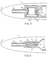
- FIGS 3 to 6 show a writing end of a writing instrument 1 having a second example of a valve 15.
- the second example of the valve 15 is similar to the first example of the valve 6 shown in Figures 1 and 2.
- the valve 15 has an elliptical cross-section with a relatively short minor axis and a relatively large major axis so that the valve 15 generally has a tall, narrow shape.
- the valve 15 therefore has two large flat opposed side walls 16 and two narrow opposed side walls 17.
- On the narrow-side wall 17 adjacent the aperture 5 is a projecting boss 18 which is of a size and shape normally to seal the aperture 5 in the reservoir 3.
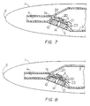
- valve 19 is shown in Figures 7 and 8.
- the valve 19 is generally cup-shaped and is retained in the recess 10 in the writing instrument 1 by the retainer 12.
- the valve 19 of the third example has a valve head 20 on a valve stem 21 which is part of the top face 22 of the main valve body 23.
- the valve head 20 sits inside the reservoir 3 and normally seals the aperture 5.
- the valve stem 21 sits in the aperture 5 and is of sufficiently small diameter to leave a gap around its circumference between the valve stem 21 and the edge of the aperture 5.
- the top, outer face 22 of the valve 19 is spaced from the end wall of the reservoir 3 having the aperture 5 so that it is subjected on one side (the side having the valve head 20) to pressure in the ink feed chamber 4.
- the other, inner side of the top face 22 is subjected to atmospheric pressure through the through-hole 14 in the retainer 12.
- ink pressure in the reservoir 3 tends to close the valve 19 since it pushes the valve head 20 into sealing engagement with the aperture 5 in the reservoir 3.
- the writing instrument is dropped, for example, or pressure in the reservoir 3 rises relative to the ambient atmospheric pressure, e.g. due to the writing instrument being taken to altitude in an aircraft or due to warming of the writing instrument in use, there is a tendency for the valve 19 to close even more firmly, ensuring a good seal.
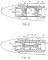
- valve cartridge 30 is fabricated of wall structure forming a reservoir 3 for containing ink which is generally at atmospheric pressure and an ink chamber 4 for conducting ink from the reservoir 3 to the writing tip 2.
- the wall structure additionally provides a valve chamber 31 having a first aperture 32 opening into the reservoir 3 and a second aperture 34 communicating between the valve chamber and the ink feed chamber 4.
- a valve 36 is disposed within the valve chamber 31, the valve being of substantially elliptical cross-section with a short minor axis and a relatively large major axis, similar to the valve structure of Figures 3 to 6.
- the valve 36 is provided with a pair of resilient arms 38 and 40 extending downwardly and outwardly from the body of the valve 36.
- the main body of the valve 36 is of resiliently flexible material as described above and is in the form of a cup, open at the bottom to atmospheric pressure, and having a bottom wall 42 which extends outwardly from the cup portion and is sealingly engaged with the bottom of the valve chamber 31.
- the bottom wall 42 of the valve 36 may be sealed at the opening of the valve chamber 31 by any suitable means such as an adhesive, the only requirement being that the seal be of a type which will retain the differential pressure to which the valve 36 is subjected during use.
- any suitable means such as an adhesive, the only requirement being that the seal be of a type which will retain the differential pressure to which the valve 36 is subjected during use.
- an arm displacement component 44 which is mounted in the writing instrument and aligned with the second aperture 34 extends through the aperture and contacts the resilient arm 40 to displace it from the aperture 34 and thus to retain the aperture open during usage of the cartridge 30.
- the arm displacement component 40 may take the form of a single ink channel capillary slot through which the ink flows during operation of the writing instrument, a multiporous feed stick or even may take the form of a conventional piercer tube mechanism.
- valve 36 functions in a similar manner to those embodiments previously discussed.
- ink flows out of the feed chamber 4 onto the paper or other medium which causes the pressure in the ink feed chamber to drop relatively to atmospheric.
- the interior of the valve 36 is maintained at atmospheric, there is a net force acting on the interior of the valve and when the pressure differential is sufficient, the net force causes the thin walls of the valve to bow outwardly as shown in Figure 11.
- the relatively small end walls move inwardly moving the resilient arm 38 inwardly, and causing the arm 38 to be displaced from the aperture 32 allowing ink to flow from the reservoir 3 into the valve chamber 31 and then outwardly into the feed chamber 4.
- Ink is therefore continuously drawn from the reservoir 3 to replenish the ink feed chamber 4, from where it is caused to pass to the writing tip 2 as necessary.
- valves described above may be used in a replaceable refill unit for a writing instrument or may be integrally provided in a writing instrument.
Landscapes
- Engineering & Computer Science (AREA)
- Mechanical Engineering (AREA)
- Pens And Brushes (AREA)
- Dental Preparations (AREA)
- Holo Graphy (AREA)
- Ink Jet (AREA)
Applications Claiming Priority (3)
| Application Number | Priority Date | Filing Date | Title |
|---|---|---|---|
| GB9325891 | 1993-12-17 | ||
| GB939325891A GB9325891D0 (en) | 1993-12-17 | 1993-12-17 | Writing instruments |
| PCT/GB1994/002696 WO1995016577A1 (en) | 1993-12-17 | 1994-12-09 | Improvements in or relating to writing instruments |
Publications (2)
| Publication Number | Publication Date |
|---|---|
| EP0734328A1 EP0734328A1 (en) | 1996-10-02 |
| EP0734328B1 true EP0734328B1 (en) | 1998-09-09 |
Family
ID=10746819
Family Applications (1)
| Application Number | Title | Priority Date | Filing Date |
|---|---|---|---|
| EP95902872A Expired - Lifetime EP0734328B1 (en) | 1993-12-17 | 1994-12-09 | Improvements in or relating to writing instruments |
Country Status (20)
| Country | Link |
|---|---|
| US (1) | US5735624A (enExample) |
| EP (1) | EP0734328B1 (enExample) |
| JP (1) | JP3664407B2 (enExample) |
| CN (1) | CN1051283C (enExample) |
| AU (1) | AU689833B2 (enExample) |
| BR (1) | BR9408350A (enExample) |
| CA (1) | CA2179277C (enExample) |
| DE (1) | DE69413252T2 (enExample) |
| EG (1) | EG20444A (enExample) |
| ES (1) | ES2120715T3 (enExample) |
| GB (1) | GB9325891D0 (enExample) |
| IL (1) | IL111812A (enExample) |
| MY (1) | MY131720A (enExample) |
| NZ (1) | NZ277070A (enExample) |
| PL (1) | PL315034A1 (enExample) |
| RU (1) | RU2123940C1 (enExample) |
| TW (1) | TW262437B (enExample) |
| UY (1) | UY23875A1 (enExample) |
| WO (1) | WO1995016577A1 (enExample) |
| ZA (1) | ZA949490B (enExample) |
Families Citing this family (10)
| Publication number | Priority date | Publication date | Assignee | Title |
|---|---|---|---|---|
| US5906446A (en) * | 1996-10-22 | 1999-05-25 | Bic Corporation | Fillerless writing instrument |
| DE19706967C1 (de) * | 1997-02-21 | 1998-09-03 | Kaufmann R Dataprint | Flüssigkeitsregler zur Versorgung eines Verbrauchers mit Flüssigkeit aus einem Flssigkeitsvorrat |
| GB9709513D0 (en) | 1997-05-09 | 1997-07-02 | Parker Pen Products | Marking instrument |
| US6004418A (en) * | 1997-10-28 | 1999-12-21 | Lear Corporation | Method of joining a cover material to a substrate utilizing electrically conductive bonding |
| DE29819071U1 (de) * | 1998-10-20 | 2000-03-02 | Anderka, Gerold, 25474 Ellerbek | Handschreib- oder -auftraggerät |
| GB2359786A (en) * | 2000-03-02 | 2001-09-05 | Gillette Co | Ink cartridge with plug and valve |
| US6916088B2 (en) * | 2001-04-20 | 2005-07-12 | Hewlett-Packard Development Company, L.P. | Ink container configured to establish reliable fluidic connection to a receiving station |
| JP4461728B2 (ja) * | 2003-07-29 | 2010-05-12 | ブラザー工業株式会社 | インクジェット記録装置及びインク供給装置 |
| JP7339823B2 (ja) * | 2019-09-17 | 2023-09-06 | 三菱鉛筆株式会社 | 塗布具 |
| JP7441655B2 (ja) * | 2020-01-22 | 2024-03-01 | 三菱鉛筆株式会社 | 塗布具 |
Family Cites Families (10)
| Publication number | Priority date | Publication date | Assignee | Title |
|---|---|---|---|---|
| US3877619A (en) * | 1974-05-15 | 1975-04-15 | Jr Evelio F Chavez | Pneumatic self-closing valve for a tube of flowable material |
| US4364684A (en) * | 1979-06-21 | 1982-12-21 | Pentel Kabushiki Kaisha | Writing instrument |
| FR2538762A1 (fr) * | 1982-12-30 | 1984-07-06 | Dupont S T | Perfectionnements aux stylographes a cartouches-recharges |
| JPS6145191U (ja) * | 1984-08-29 | 1986-03-25 | パイロツトインキ株式会社 | 筆記具 |
| US4588319A (en) * | 1984-10-25 | 1986-05-13 | Nicolet Instrument Corporation | Marking instrument |
| FR2580234B1 (fr) * | 1985-04-17 | 1989-07-07 | Mitsubishi Pencil Co | Instrument pour ecrire, peindre ou analogue |
| DE3772608D1 (de) * | 1986-04-10 | 1991-10-10 | Jiro Hori | Geraet, zum beispiel schreibstift, zum aufbringen von fluessigkeit. |
| EP0413273A1 (en) * | 1989-08-14 | 1991-02-20 | Jiro Hori | Valve for a writing instrument |
| DE4013510C2 (de) * | 1990-04-27 | 1995-04-20 | Rotring Int Gmbh | Röhrchenschreiberspitze, insbesondere für die Verwendung in Zeichenplottern |
| DE4135605A1 (de) * | 1991-10-29 | 1993-05-06 | Rotring-Werke Riepe Kg, 2000 Hamburg, De | Schreib- oder zeichengeraet |
-
1993
- 1993-12-17 GB GB939325891A patent/GB9325891D0/en active Pending
-
1994
- 1994-01-20 TW TW083100469A patent/TW262437B/zh active
- 1994-11-29 ZA ZA949490A patent/ZA949490B/xx unknown
- 1994-11-29 IL IL111812A patent/IL111812A/en active IP Right Grant
- 1994-12-09 BR BR9408350A patent/BR9408350A/pt not_active Application Discontinuation
- 1994-12-09 CA CA002179277A patent/CA2179277C/en not_active Expired - Fee Related
- 1994-12-09 JP JP51659395A patent/JP3664407B2/ja not_active Expired - Fee Related
- 1994-12-09 NZ NZ277070A patent/NZ277070A/en unknown
- 1994-12-09 EP EP95902872A patent/EP0734328B1/en not_active Expired - Lifetime
- 1994-12-09 US US08/663,242 patent/US5735624A/en not_active Expired - Lifetime
- 1994-12-09 PL PL94315034A patent/PL315034A1/xx unknown
- 1994-12-09 WO PCT/GB1994/002696 patent/WO1995016577A1/en not_active Ceased
- 1994-12-09 RU RU96115188A patent/RU2123940C1/ru active
- 1994-12-09 CN CN94194510A patent/CN1051283C/zh not_active Expired - Fee Related
- 1994-12-09 ES ES95902872T patent/ES2120715T3/es not_active Expired - Lifetime
- 1994-12-09 DE DE69413252T patent/DE69413252T2/de not_active Expired - Fee Related
- 1994-12-09 AU AU11962/95A patent/AU689833B2/en not_active Ceased
- 1994-12-12 MY MYPI94003313A patent/MY131720A/en unknown
- 1994-12-13 EG EG78294A patent/EG20444A/xx active
- 1994-12-19 UY UY23875A patent/UY23875A1/es not_active IP Right Cessation
Also Published As
| Publication number | Publication date |
|---|---|
| IL111812A (en) | 1998-06-15 |
| MY131720A (en) | 2007-08-30 |
| NZ277070A (en) | 1998-06-26 |
| PL315034A1 (en) | 1996-09-30 |
| EG20444A (en) | 1999-04-29 |
| JP3664407B2 (ja) | 2005-06-29 |
| ES2120715T3 (es) | 1998-11-01 |
| CN1051283C (zh) | 2000-04-12 |
| CA2179277A1 (en) | 1995-06-22 |
| GB9325891D0 (en) | 1994-02-23 |
| CA2179277C (en) | 2000-02-08 |
| CN1137773A (zh) | 1996-12-11 |
| AU1196295A (en) | 1995-07-03 |
| EP0734328A1 (en) | 1996-10-02 |
| WO1995016577A1 (en) | 1995-06-22 |
| AU689833B2 (en) | 1998-04-09 |
| RU2123940C1 (ru) | 1998-12-27 |
| BR9408350A (pt) | 1997-08-26 |
| US5735624A (en) | 1998-04-07 |
| IL111812A0 (en) | 1995-01-24 |
| DE69413252T2 (de) | 1999-04-15 |
| ZA949490B (en) | 1995-08-14 |
| UY23875A1 (es) | 1995-06-13 |
| JPH09506562A (ja) | 1997-06-30 |
| TW262437B (enExample) | 1995-11-11 |
| DE69413252D1 (de) | 1998-10-15 |
Similar Documents
| Publication | Publication Date | Title |
|---|---|---|
| US6053604A (en) | Ink refilling method and apparatus for ink cartridge | |
| US6550901B2 (en) | Ink cartridge for ink jet printer | |
| EP0734328B1 (en) | Improvements in or relating to writing instruments | |
| US6186620B1 (en) | Ink pressure control apparatus for ink-jet pens | |
| US7475972B2 (en) | One-way valve, valve unit assembly, and ink cartridge using the same | |
| US3397939A (en) | Marking instrument | |
| US6164858A (en) | Fluid regulator for supplying a consumer element with fluid from a fluid reservoir | |
| JP2008195081A (ja) | インクジェット記録装置用インクカートリッジ | |
| US6106180A (en) | Handwriting or ink applying device | |
| EP0472660B1 (en) | A pen | |
| RU96115188A (ru) | Контейнер для чернил пишущего прибора | |
| US3187724A (en) | Writing instrument | |
| US7048459B2 (en) | Liquid ink writing instrument with a shape memory valve | |
| JPH0576429B2 (enExample) | ||
| JP3924933B2 (ja) | 筆記具 | |
| JP3179589B2 (ja) | 筆記具 | |
| JPH0556487U (ja) | 生インキ式塗布具 | |
| JP3632289B2 (ja) | インキタンク | |
| JP2560925Y2 (ja) | 筆記具 | |
| JP3904084B2 (ja) | インクカートリッジ | |
| JP3659351B2 (ja) | インクカートリッジ | |
| JPH10236060A (ja) | インキタンク | |
| JPH09156122A (ja) | インキタンク | |
| JPH1178349A (ja) | 筆記具 | |
| JPH0692082A (ja) | 筆記具 |
Legal Events
| Date | Code | Title | Description |
|---|---|---|---|
| PUAI | Public reference made under article 153(3) epc to a published international application that has entered the european phase |
Free format text: ORIGINAL CODE: 0009012 |
|
| 17P | Request for examination filed |
Effective date: 19960712 |
|
| AK | Designated contracting states |
Kind code of ref document: A1 Designated state(s): DE ES FR GB IT |
|
| 17Q | First examination report despatched |
Effective date: 19960912 |
|
| GRAG | Despatch of communication of intention to grant |
Free format text: ORIGINAL CODE: EPIDOS AGRA |
|
| GRAG | Despatch of communication of intention to grant |
Free format text: ORIGINAL CODE: EPIDOS AGRA |
|
| GRAH | Despatch of communication of intention to grant a patent |
Free format text: ORIGINAL CODE: EPIDOS IGRA |
|
| GRAH | Despatch of communication of intention to grant a patent |
Free format text: ORIGINAL CODE: EPIDOS IGRA |
|
| GRAA | (expected) grant |
Free format text: ORIGINAL CODE: 0009210 |
|
| AK | Designated contracting states |
Kind code of ref document: B1 Designated state(s): DE ES FR GB IT |
|
| REF | Corresponds to: |
Ref document number: 69413252 Country of ref document: DE Date of ref document: 19981015 |
|
| REG | Reference to a national code |
Ref country code: ES Ref legal event code: FG2A Ref document number: 2120715 Country of ref document: ES Kind code of ref document: T3 |
|
| ET | Fr: translation filed | ||
| PLBE | No opposition filed within time limit |
Free format text: ORIGINAL CODE: 0009261 |
|
| STAA | Information on the status of an ep patent application or granted ep patent |
Free format text: STATUS: NO OPPOSITION FILED WITHIN TIME LIMIT |
|
| 26N | No opposition filed | ||
| PGFP | Annual fee paid to national office [announced via postgrant information from national office to epo] |
Ref country code: ES Payment date: 20010112 Year of fee payment: 7 |
|
| REG | Reference to a national code |
Ref country code: GB Ref legal event code: IF02 |
|
| PG25 | Lapsed in a contracting state [announced via postgrant information from national office to epo] |
Ref country code: ES Free format text: LAPSE BECAUSE OF NON-PAYMENT OF DUE FEES Effective date: 20021210 |
|
| PGFP | Annual fee paid to national office [announced via postgrant information from national office to epo] |
Ref country code: FR Payment date: 20031210 Year of fee payment: 10 |
|
| PGFP | Annual fee paid to national office [announced via postgrant information from national office to epo] |
Ref country code: DE Payment date: 20031218 Year of fee payment: 10 |
|
| REG | Reference to a national code |
Ref country code: ES Ref legal event code: FD2A Effective date: 20030113 |
|
| PG25 | Lapsed in a contracting state [announced via postgrant information from national office to epo] |
Ref country code: DE Free format text: LAPSE BECAUSE OF NON-PAYMENT OF DUE FEES Effective date: 20050701 |
|
| PG25 | Lapsed in a contracting state [announced via postgrant information from national office to epo] |
Ref country code: FR Free format text: LAPSE BECAUSE OF NON-PAYMENT OF DUE FEES Effective date: 20050831 |
|
| REG | Reference to a national code |
Ref country code: FR Ref legal event code: ST |
|
| PG25 | Lapsed in a contracting state [announced via postgrant information from national office to epo] |
Ref country code: IT Free format text: LAPSE BECAUSE OF NON-PAYMENT OF DUE FEES;WARNING: LAPSES OF ITALIAN PATENTS WITH EFFECTIVE DATE BEFORE 2007 MAY HAVE OCCURRED AT ANY TIME BEFORE 2007. THE CORRECT EFFECTIVE DATE MAY BE DIFFERENT FROM THE ONE RECORDED. Effective date: 20051209 |
|
| PGFP | Annual fee paid to national office [announced via postgrant information from national office to epo] |
Ref country code: GB Payment date: 20101229 Year of fee payment: 17 |
|
| GBPC | Gb: european patent ceased through non-payment of renewal fee |
Effective date: 20121209 |
|
| PG25 | Lapsed in a contracting state [announced via postgrant information from national office to epo] |
Ref country code: GB Free format text: LAPSE BECAUSE OF NON-PAYMENT OF DUE FEES Effective date: 20121209 |