EP0733795A2 - Système d'alimentation en carburant pour moteurs à combustion - Google Patents
Système d'alimentation en carburant pour moteurs à combustion Download PDFInfo
- Publication number
- EP0733795A2 EP0733795A2 EP95120482A EP95120482A EP0733795A2 EP 0733795 A2 EP0733795 A2 EP 0733795A2 EP 95120482 A EP95120482 A EP 95120482A EP 95120482 A EP95120482 A EP 95120482A EP 0733795 A2 EP0733795 A2 EP 0733795A2
- Authority
- EP
- European Patent Office
- Prior art keywords
- pressure
- fuel
- pressure regulator
- valve
- regulator
- Prior art date
- Legal status (The legal status is an assumption and is not a legal conclusion. Google has not performed a legal analysis and makes no representation as to the accuracy of the status listed.)
- Withdrawn
Links
Images

Classifications
-
- F—MECHANICAL ENGINEERING; LIGHTING; HEATING; WEAPONS; BLASTING
- F02—COMBUSTION ENGINES; HOT-GAS OR COMBUSTION-PRODUCT ENGINE PLANTS
- F02M—SUPPLYING COMBUSTION ENGINES IN GENERAL WITH COMBUSTIBLE MIXTURES OR CONSTITUENTS THEREOF
- F02M37/00—Apparatus or systems for feeding liquid fuel from storage containers to carburettors or fuel-injection apparatus; Arrangements for purifying liquid fuel specially adapted for, or arranged on, internal-combustion engines
- F02M37/0011—Constructional details; Manufacturing or assembly of elements of fuel systems; Materials therefor
- F02M37/0023—Valves in the fuel supply and return system
- F02M37/0029—Pressure regulator in the low pressure fuel system
-
- F—MECHANICAL ENGINEERING; LIGHTING; HEATING; WEAPONS; BLASTING
- F02—COMBUSTION ENGINES; HOT-GAS OR COMBUSTION-PRODUCT ENGINE PLANTS
- F02M—SUPPLYING COMBUSTION ENGINES IN GENERAL WITH COMBUSTIBLE MIXTURES OR CONSTITUENTS THEREOF
- F02M69/00—Low-pressure fuel-injection apparatus ; Apparatus with both continuous and intermittent injection; Apparatus injecting different types of fuel
- F02M69/46—Details, component parts or accessories not provided for in, or of interest apart from, the apparatus covered by groups F02M69/02 - F02M69/44
- F02M69/54—Arrangement of fuel pressure regulators
-
- G—PHYSICS
- G05—CONTROLLING; REGULATING
- G05D—SYSTEMS FOR CONTROLLING OR REGULATING NON-ELECTRIC VARIABLES
- G05D16/00—Control of fluid pressure
- G05D16/04—Control of fluid pressure without auxiliary power
- G05D16/0402—Control of fluid pressure without auxiliary power with two or more controllers mounted in series
-
- G—PHYSICS
- G05—CONTROLLING; REGULATING
- G05D—SYSTEMS FOR CONTROLLING OR REGULATING NON-ELECTRIC VARIABLES
- G05D16/00—Control of fluid pressure
- G05D16/04—Control of fluid pressure without auxiliary power
- G05D16/06—Control of fluid pressure without auxiliary power the sensing element being a flexible membrane, yielding to pressure, e.g. diaphragm, bellows, capsule
- G05D16/063—Control of fluid pressure without auxiliary power the sensing element being a flexible membrane, yielding to pressure, e.g. diaphragm, bellows, capsule the sensing element being a membrane
- G05D16/0644—Control of fluid pressure without auxiliary power the sensing element being a flexible membrane, yielding to pressure, e.g. diaphragm, bellows, capsule the sensing element being a membrane the membrane acting directly on the obturator
- G05D16/0655—Control of fluid pressure without auxiliary power the sensing element being a flexible membrane, yielding to pressure, e.g. diaphragm, bellows, capsule the sensing element being a membrane the membrane acting directly on the obturator using one spring-loaded membrane
-
- F—MECHANICAL ENGINEERING; LIGHTING; HEATING; WEAPONS; BLASTING
- F02—COMBUSTION ENGINES; HOT-GAS OR COMBUSTION-PRODUCT ENGINE PLANTS
- F02M—SUPPLYING COMBUSTION ENGINES IN GENERAL WITH COMBUSTIBLE MIXTURES OR CONSTITUENTS THEREOF
- F02M37/00—Apparatus or systems for feeding liquid fuel from storage containers to carburettors or fuel-injection apparatus; Arrangements for purifying liquid fuel specially adapted for, or arranged on, internal-combustion engines
- F02M37/0047—Layout or arrangement of systems for feeding fuel
- F02M37/0052—Details on the fuel return circuit; Arrangement of pressure regulators
-
- Y—GENERAL TAGGING OF NEW TECHNOLOGICAL DEVELOPMENTS; GENERAL TAGGING OF CROSS-SECTIONAL TECHNOLOGIES SPANNING OVER SEVERAL SECTIONS OF THE IPC; TECHNICAL SUBJECTS COVERED BY FORMER USPC CROSS-REFERENCE ART COLLECTIONS [XRACs] AND DIGESTS
- Y10—TECHNICAL SUBJECTS COVERED BY FORMER USPC
- Y10T—TECHNICAL SUBJECTS COVERED BY FORMER US CLASSIFICATION
- Y10T137/00—Fluid handling
- Y10T137/2496—Self-proportioning or correlating systems
- Y10T137/2559—Self-controlled branched flow systems
- Y10T137/2574—Bypass or relief controlled by main line fluid condition
- Y10T137/2605—Pressure responsive
Definitions
- the invention relates to a fuel supply system for internal combustion engines according to the preamble of patent claim 1.
- Such systems consist of a fuel pump and a pressure regulator, the pressure regulator being arranged downstream of a distributor bar and allowing excess fuel to flow off into the fuel tank.
- the fuel pump works with a large delivery rate against the regulated fuel pressure.
- a supply device in which a pressure switch inserted between the fuel pump and the distributor strip switches between conductive and non-conductive depending on the pump outlet pressure and thereby the fuel pump is supplied with a different electrical power via a control circuit when the pump outlet pressure is one Threshold value of the pressure switch exceeds or falls below.
- a device for controlling the fuel supply in which a pressure regulator adjusts a switch / resistor, the resistance of which depends on the amount of fuel flowing back depending on the power supply of the fuel pump controls.
- a pressure regulator adjusts a switch / resistor, the resistance of which depends on the amount of fuel flowing back depending on the power supply of the fuel pump controls.
- the object of the invention is to design a generic fuel supply system in such a way that there is a reduced pressure fluctuation on the distributor strip, no increase in fuel temperature caused by engine waste heat and, in addition, pump operation with an overall reduced power supply can be achieved.
- Fig. 1 shows schematically an inventive fuel supply system for internal combustion engines, formed from a fuel pump 1, the one Fuel tank 2 is connected and delivers to the internal combustion engine via a fuel pressure line 3.
- a pressure regulator 4 and subsequently a reducing pressure regulator 5 are arranged, the output line 6 of which is connected to a distributor rail 7 of the internal combustion engine.
- a return line 8 leads back into the tank 2, via which fuel that is not required by the internal combustion engine flows back.
- the reducing pressure regulator 5 is set so that the reducing pressure is lower than the pressure regulated by the pressure regulator 4.
- the use of the reducing pressure regulator 5 ensures that the pressure fluctuations in the fuel pressure line 3 emanating from the pressure regulator 4 do not penetrate into the distributor rail 7.
- the pressure regulator 4 has a large storage volume, which results in a large adjustment path for a pressure regulating valve 9 of the pressure regulator 4. It is provided that the pressure control valve 9 sets a large return flow into the tank when the fuel volume is large and a small / no return flow when the fuel volume is small.
- the pressure control valve 9 is designed as an open-close valve, it is provided that the pressure regulator 4 operates with a large switching hysteresis and, in the case of a large fuel volume, opens the pressure control valve and does not close any of it.
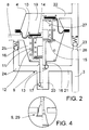
- the pressure regulator 4 has a membrane 10 delimiting the storage volume, which increases the storage volume counter to a spring 11, the adjustment taking place being transferred to a pin 12 connected to the membrane 10.
- This pin 12 receives a valve lifter 13 which counteracts under the force of a spring 14 a pin collar 15 is created.
- the valve tappet 13 projects through a valve opening 16 and has a valve closing body 17 at the projecting end, here with an O-ring.
- An existing between the valve opening 16 and membrane 10 membrane chamber 18 is connected via the return line 8 to the tank 2, so that there is essentially ambient pressure in this membrane chamber 18.
- a storage membrane chamber 19 which limits the storage volume is connected to the fuel pressure line 3, as is a valve chamber 20 which receives the valve closing body 17, the fuel pressure line 3 having a check valve 23 between a branch 21 to the valve chamber 20 and a branch 22 to the storage membrane chamber 19.
- a bypass duct 24 arranged for valve opening 16, the function of which will be described later, has a pressure valve 25.
- the fuel pump 1 delivers via the check valve 23 into the accumulator diaphragm chamber 19 and to the reducing pressure regulator 5.
- the pressure in the fuel pressure line 3 is higher than that of the reducing regulator 5 regulated, so that there is fuel under working pressure on the distributor rail 7.
- the fuel under pressure also reaches the closed pressure control valve 9 and loads the valve closing body 17 against the membrane chamber 18 under ambient pressure and holds the valve tappet 13 in the closed position until the spring 14 tensioning during the diaphragm pin adjustment has a larger one Has force than the closing force or a pin 26 of the valve tappet 13 meets the diaphragm bottom 27, so that the pressure control valve 19 through the membrane force is opened and suddenly opens until the valve tappet 13 bears against the pin collar 15.
- the fuel pressure line 3 upstream of the check valve 23 is acted upon by the ambient pressure prevailing in the membrane chamber 18, the check valve 23 closes and the fuel pump 1 only delivers against the ambient pressure with reduced power consumption.
- the pressure Downstream of the check valve 23, the pressure is maintained by the fuel storage volume in the storage membrane chamber 19 until the valve tappet 13 moves with the membrane pin 12, the pressure control valve 9 closes and the process is repeated.
- the closing force acting on the valve closing body 17 can be limited by the pressure valve 25 arranged in the bypass channel 24.
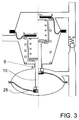
- Fig. 3 shows an alternative embodiment of the pressure control valve 9, in which, with the same structure as shown in Fig. 2, the valve tappet 13 is connected to a snap spring 28 which increases the closing force of the valve closing body 17 on the pressure control valve 9.
- Fig. 4 shows a further alternative embodiment, in which the pressure control valve 9 is designed as a proportional valve 29, i. H. with a larger fuel storage volume, the amount of fuel flowing back through the pressure control valve 9 becomes larger.
- the reducing regulator can be acted upon by the air intake pressure of the internal combustion engine via a line 30.
- the membrane of the present embodiment can also be replaced by a piston.
Landscapes
- Engineering & Computer Science (AREA)
- Physics & Mathematics (AREA)
- Fluid Mechanics (AREA)
- General Physics & Mathematics (AREA)
- Automation & Control Theory (AREA)
- Chemical & Material Sciences (AREA)
- Combustion & Propulsion (AREA)
- Mechanical Engineering (AREA)
- General Engineering & Computer Science (AREA)
- Fuel-Injection Apparatus (AREA)
Applications Claiming Priority (2)
| Application Number | Priority Date | Filing Date | Title |
|---|---|---|---|
| DE19510497 | 1995-03-23 | ||
| DE19510497A DE19510497A1 (de) | 1995-03-23 | 1995-03-23 | Brennstoffversorgungssystem für Brennkraftmaschinen |
Publications (2)
| Publication Number | Publication Date |
|---|---|
| EP0733795A2 true EP0733795A2 (fr) | 1996-09-25 |
| EP0733795A3 EP0733795A3 (fr) | 1997-07-09 |
Family
ID=7757430
Family Applications (1)
| Application Number | Title | Priority Date | Filing Date |
|---|---|---|---|
| EP95120482A Withdrawn EP0733795A3 (fr) | 1995-03-23 | 1995-12-22 | Système d'alimentation en carburant pour moteurs à combustion |
Country Status (3)
| Country | Link |
|---|---|
| US (1) | US5706785A (fr) |
| EP (1) | EP0733795A3 (fr) |
| DE (1) | DE19510497A1 (fr) |
Families Citing this family (8)
| Publication number | Priority date | Publication date | Assignee | Title |
|---|---|---|---|---|
| DE19805070C2 (de) * | 1998-02-09 | 1999-11-25 | Bosch Gmbh Robert | Kraftstoff-Fördermodul für eine Benzindirekteinspeisung einer Brennkraftmaschine mit einem Ventil |
| US5842455A (en) * | 1998-03-24 | 1998-12-01 | Walbro Corporation | Fuel accumulator and pressure limiting device |
| DE19936287C2 (de) | 1999-08-02 | 2003-04-30 | Bosch Gmbh Robert | Bedarfssteuerung für ein Kraftstoffördermodul mit variablem Systemdruck |
| US6401693B1 (en) * | 2000-09-01 | 2002-06-11 | Schrader-Bridgeport International, Inc. | Pressure spike attenuator for automotive fuel injection system |
| DE10143892A1 (de) * | 2001-09-07 | 2003-03-27 | Pierburg Gmbh | Vorducksteueranordnung |
| US7458362B2 (en) * | 2006-03-29 | 2008-12-02 | Denso Corporation | Fuel supply system for internal combustion engine |
| US7757672B2 (en) * | 2008-09-15 | 2010-07-20 | Gm Global Technology Operations, Inc. | Anti-clogging fuel pump module |
| US11754028B2 (en) * | 2021-06-23 | 2023-09-12 | Ford Global Technologies, Llc | Fuel system diaphragm valve |
Family Cites Families (14)
| Publication number | Priority date | Publication date | Assignee | Title |
|---|---|---|---|---|
| DE2752885A1 (de) * | 1977-11-26 | 1979-05-31 | Porsche Ag | Brennstoffversorgungssystem fuer eine gemischverdichtende, fremdgezuendete viertakt-brennkraftmaschine mit ladungsschichtung |
| GB2070802B (en) * | 1980-01-31 | 1984-08-22 | Nissan Motor | Control of fuel supply to an ic engine |
| US4310142A (en) * | 1980-03-13 | 1982-01-12 | Tom Mcguane Industries, Inc. | Fuel pressure regulator assembly |
| WO1992008886A1 (fr) * | 1990-11-20 | 1992-05-29 | Biocom Pty. Ltd. | Procede d'injection de carburant |
| DE4136833A1 (de) * | 1991-11-08 | 1993-05-13 | Bayerische Motoren Werke Ag | Anordnung zur kraftstoff-versorgung einer brennkraftmaschine |
| JPH05157015A (ja) * | 1991-12-04 | 1993-06-22 | Nippondenso Co Ltd | 燃料装置 |
| US5195494A (en) * | 1992-02-27 | 1993-03-23 | Walbro Corporation | Fuel delivery system with outlet pressure regulation |
| DE4224981C2 (de) * | 1992-07-29 | 2003-06-26 | Bosch Gmbh Robert | Einrichtung zum Fördern von Kraftstoff aus einem Vorratstank zur Brennkraftmaschine eines Kraftfahrzeuges |
| FR2695964B1 (fr) * | 1992-09-24 | 1995-07-21 | Walbro Corp | Circuit de distribution de carburant pour moteur a combustion interne. |
| JP2853504B2 (ja) * | 1993-03-16 | 1999-02-03 | 日産自動車株式会社 | 内燃機関の燃料噴射装置 |
| FR2709516B1 (fr) * | 1993-09-03 | 1995-10-20 | Peugeot | Circuit d'alimentation en carburant d'un moteur à combustion interne et dispositif formant régulateur de débit de carburant pouvant être utilisé dans un tel circuit d'alimentation. |
| US5398655A (en) * | 1994-01-14 | 1995-03-21 | Walbro Corporation | Manifold referenced returnless fuel system |
| US5529035A (en) * | 1994-11-08 | 1996-06-25 | Hitachi America, Ltd. | Cold start fuel injector with heater |
| FR2730526B1 (fr) * | 1995-02-13 | 1997-05-09 | Marwal Systems | Dispositif d'alimentation en carburant pour vehicule automobile avec regulation de pression |
-
1995
- 1995-03-23 DE DE19510497A patent/DE19510497A1/de not_active Withdrawn
- 1995-12-22 EP EP95120482A patent/EP0733795A3/fr not_active Withdrawn
-
1996
- 1996-03-25 US US08/621,224 patent/US5706785A/en not_active Expired - Fee Related
Also Published As
| Publication number | Publication date |
|---|---|
| EP0733795A3 (fr) | 1997-07-09 |
| US5706785A (en) | 1998-01-13 |
| DE19510497A1 (de) | 1996-09-26 |
Similar Documents
| Publication | Publication Date | Title |
|---|---|---|
| EP1352174B1 (fr) | Systeme d'injection de carburant avec regulation de la pression dans la conduite de retour | |
| DE2846269A1 (de) | Brennstoffadditiv-einspritzsystem fuer dieselmotoren | |
| DE102016207743A1 (de) | Einrichtung zur Zumessung eines gasförmigen Brennstoffs zu einem Injektor | |
| DE19510494A1 (de) | Brennstoffversorgungssystem für Brennkraftmaschinen | |
| EP0733795A2 (fr) | Système d'alimentation en carburant pour moteurs à combustion | |
| WO2011128163A1 (fr) | Ensemble pompe | |
| DE2622106C2 (de) | Kraftstoffeinspritzeinrichtung für Brennkraftmaschinen | |
| DE102008002462A1 (de) | Kraftstoffversorgungseinrichtung | |
| EP0069912B1 (fr) | Dispositif d'alimentation de combustible pour moteurs à conbustion interne | |
| DE2423109A1 (de) | Kraftstoffeinspritzanlage | |
| EP0483301B1 (fr) | Systeme d'alimentation en carburant pour un moteur a combustion interne | |
| WO1991019892A1 (fr) | Procede pour le reglage de la quantite de carburant d'un moteur a combustion interne | |
| DE29509775U1 (de) | Brennstoffversorgungssystem für Brennkraftmaschinen | |
| DE2444598C2 (de) | Kraftstoffeinspritzanlage | |
| EP0435965B1 (fr) | Systeme de commande pour l'arret d'un moteur a combustion interne | |
| DE29509774U1 (de) | Brennstoffversorgungssystem für Brennkraftmaschinen | |
| DE2349688A1 (de) | Kraftstoffeinspritzanlage | |
| DE3130911C2 (de) | Brennstoffversorgungseinrichtung | |
| DE19524413B4 (de) | Kraftstoffaufbereitungsanlage für gasförmigen Brennstoff | |
| DE2623122A1 (de) | Druckregelventil fuer eine kraftstoffeinspritzanlage | |
| DE3343693A1 (de) | Anordnung zum regulieren der leerlaufdrehzahl eines verbrennungsmotors | |
| DE19635068C2 (de) | Vorrichtung für ein Kraftstoffversorgungssystem einer aufgeladenen Brennkraftmaschine | |
| DE10257134A1 (de) | Vorrichtung zur Aufrechterhaltung eines Solldruckes im Kraftstoff-Hochdruckspeicher eines Speichereinspritzsystems | |
| DE10318941A1 (de) | Kraftstoffsystem für eine Brennkraftmaschine | |
| DE102010042573A1 (de) | Drosseleinrichtung |
Legal Events
| Date | Code | Title | Description |
|---|---|---|---|
| PUAI | Public reference made under article 153(3) epc to a published international application that has entered the european phase |
Free format text: ORIGINAL CODE: 0009012 |
|
| 17P | Request for examination filed |
Effective date: 19951222 |
|
| AK | Designated contracting states |
Kind code of ref document: A2 Designated state(s): DE ES FR GB IT |
|
| PUAL | Search report despatched |
Free format text: ORIGINAL CODE: 0009013 |
|
| AK | Designated contracting states |
Kind code of ref document: A3 Designated state(s): DE ES FR GB IT |
|
| 17Q | First examination report despatched |
Effective date: 19991130 |
|
| STAA | Information on the status of an ep patent application or granted ep patent |
Free format text: STATUS: THE APPLICATION HAS BEEN WITHDRAWN |
|
| 18W | Application withdrawn |
Withdrawal date: 20000414 |