EP0732814A2 - Système de communication bidirectionnel par satellite avec partage d'une même bande de fréquences par superposition des fréquences des signaux - Google Patents
Système de communication bidirectionnel par satellite avec partage d'une même bande de fréquences par superposition des fréquences des signaux Download PDFInfo
- Publication number
- EP0732814A2 EP0732814A2 EP96103664A EP96103664A EP0732814A2 EP 0732814 A2 EP0732814 A2 EP 0732814A2 EP 96103664 A EP96103664 A EP 96103664A EP 96103664 A EP96103664 A EP 96103664A EP 0732814 A2 EP0732814 A2 EP 0732814A2
- Authority
- EP
- European Patent Office
- Prior art keywords
- signal
- satellite
- transmission
- local
- station
- Prior art date
- Legal status (The legal status is an assumption and is not a legal conclusion. Google has not performed a legal analysis and makes no representation as to the accuracy of the status listed.)
- Withdrawn
Links
Images


Classifications
-
- H—ELECTRICITY
- H04—ELECTRIC COMMUNICATION TECHNIQUE
- H04B—TRANSMISSION
- H04B7/00—Radio transmission systems, i.e. using radiation field
- H04B7/14—Relay systems
- H04B7/15—Active relay systems
- H04B7/185—Space-based or airborne stations; Stations for satellite systems
- H04B7/1851—Systems using a satellite or space-based relay
- H04B7/18517—Transmission equipment in earth stations
-
- H—ELECTRICITY
- H04—ELECTRIC COMMUNICATION TECHNIQUE
- H04B—TRANSMISSION
- H04B7/00—Radio transmission systems, i.e. using radiation field
- H04B7/14—Relay systems
- H04B7/15—Active relay systems
- H04B7/185—Space-based or airborne stations; Stations for satellite systems
- H04B7/1851—Systems using a satellite or space-based relay
- H04B7/18513—Transmission in a satellite or space-based system
Definitions
- the present invention relates to a satellite communications system and method capable of efficiently using a frequency band of satellite communications.
- two signals of the same frequency band can be separated by utilizing the directivity of an antenna at each earth station. Even if the same satellite is used, two signals of orthogonally polarized vertical and horizontal waves can be discriminated by an orthogonal polarization band splitter.
- the same frequency band cannot be shared for the transmission of two signals of the same polarization via the same satellite.
- FIG. 12 An example of the prior art satellite communications system is illustrated in Fig. 12.
- This example shows bidirectional communications between two stations A and B (earth stations). Two signals are transmitted, one signal S A (A ⁇ B) being transmitted from station A to station B and the other signal S B (B ⁇ A) being transmitted from station B to station A. If the bands of two signals are superposed, both the signals cannot be received.
- Frequency division multiple access (FDMA) and time division multiple access (TDMA) have been used as a means for avoiding signal superposition.
- FDMA frequency division multiple access
- two stations A and B transmit signals S A and S B at different frequency bands in order to avoid signal superposition and allow bidirectional communications. It is therefore necessary to occupy the bandwidth (BW (A ⁇ B) + (BW (B ⁇ A) which is a sum of the bandwidth BW (A ⁇ B) required for signal transmission from station A to station B and the bandwidth BW (B ⁇ A) required for signal transmission from station B to station A.
- TDMA time division multiple access
- two stations A and B transmit signals S A and S B in a burst form at predetermined timings in such a synchronous manner that two signals are not superposed in the time domain at the repeater of a satellite.
- the transmission is controlled so that while the signal from station A is reaching the satellite, the signal from station B is not reaching the satellite, and vice versa. Since each station transmits a signal in a batch manner in a limited time, the necessary bandwidth increases.
- bandwidth (BW (A ⁇ B) + (BW (B ⁇ A) which is a sum of the bandwidth BW (A ⁇ B) required for transmission of the signal S A from station A to station B and the bandwidth BW (B ⁇ A) required for transmission of the signal S B from station B to station A.
- Complicated synchronizing equipments are also required.
- CDMA Code division multiple access
- interference compensation is known which is used as a means for correctly separating a reception signal (desired wave) from a reception obstacle signal (interference signal) superposed upon the reception signal.
- This technology is adopted to eliminate a reception failure in satellite communications to be caused by superposed waves in a satellite system and a terrestrial system.
- This technology basically relies upon an auxiliary antenna which has such a directivity that only waves of the terrestrial system can receive. Specifically, if waves (interference waves) of the terrestrial system superpose upon reception waves (desired wave) of the satellite system because of the side lobe characteristics of a satellite wave reception antenna (main antenna), another auxiliary antenna receiving only interference waves of the terrestrial system is used for cancelling the interference wave components contained in the reception waves of the main antenna.
- a conventional earth station in satellite communications is not provided with a function of cancelling a local transmission signal (satellite return signal) contained in its reception signal. Therefore, a plurality of signals superposed one upon another cannot be used on the same frequency band.
- a local transmission signal (satellite return signal) of stations A and B becomes an interference signal hindering normal reception, as different from conventional technologies.
- This interference signal comes from the same satellite as the desired wave so that it is not possible to receive only the interference signal by utilizing the antenna directivity.
- each station has no function of removing such an interference signal.
- a frequency band is intended to be used efficiently through incorporation of interference
- a local transmission signal (S A or S B ) cannot be separated from its reception signal by utilizing the antenna directivity characteristics and spatial diversity, as different from interference of a terrestrial wave which can be cancelled by conventional interference compensation technology.
- each local station since each earth station has its local transmission information, each local station generates a signal same as the local transmission signal components contained in its reception signal, and adds the generated signal having the same amplitude as, and the opposite phase to, those of the local transmission signal components to the reception signal to cancel or offset the local transmission signal components. In this manner, a signal of the same frequency band transmitted from a remote station can be correctly received.
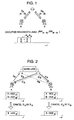
- Fig. 1 illustrates the concepts of the present invention.
- Fig. 2 is a diagram illustrating the operation of an embodiment of the present invention.
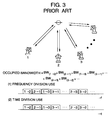
- Fig. 3 is a diagram illustrating conventional multi-site communications.
- Fig. 4 is a diagram illustrating multi-site communications.
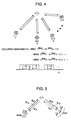
- Fig. 5 is a diagram illustrating a very small aperture terminal (VSAT) system.
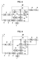
- Fig. 6 is a block diagram showing the structure of an embodiment of the present invention.
- Fig. 7 is a block diagram showing the structure of another embodiment of the present invention.
- Fig. 8 is a block diagram showing the structure of a further embodiment of the present invention.
- Fig. 9 is a block diagram showing the structure of a still further embodiment of the present invention.
- Fig. 10 is a diagram showing an example of a phase control circuit used by the embodiments of the present invention.
- Fig. 11 is a diagram showing another example of a phase control circuit used by the embodiments of the present invention.
- Fig. 12 is a diagram illustrating the concepts of conventional technology.
- Figs. 2 to 5 are diagrams used for describing the concepts of the present invention.
- Fig. 2 shows an example of bidirectional communications between two stations.
- both earth stations A and B receive a superposed signal of S' A and S' B from the satellite.
- Earth station A has a signal S A and cancels the satellite return signal S' A by using the signal S A to obtain a signal S' B transmitted from earth station B via the satellite.
- Earth station B has a signal S B and cancels the satellite return signal S' B by using the signal S B to obtain a signal S' A transmitted from earth station A via the satellite.
- the signal (S' A + S' B ) received from the satellite is added by an adder to a signal (S' A or S' B ) for cancelling a local transmission signal contained in the received signal (S' A + S' B ).
- Signals at input and output ports of the adder are given by the following equations.
- S(t) S 1 (t-t 0 )exp[j ⁇ 1 (t-t 0 )+ ⁇ 1 ⁇ ] + S 2 (t-t 2 )exp[j ⁇ 2 (t-t 2 )+ ⁇ 2 ⁇ ]
- t 0 is a time required for a radio wave to reach the satellite and return to earth station A or B.
- a storage means for delaying (storing) local transmission signal information by a time (about 0.24 sec) required for satellite return propagation is provided.
- the delay time varies with drifts of the satellite. This variation can be compensated by controlling the timing when the data in the memory is read. By using this baseband data stored in the buffer (memory), a modulated wave is generated.
- the amplitude and phase of the modulated wave are adjusted to have the same amplitude as, and the opposite phase to, those of the local transmission signal components contained in the reception signal, and are added to the reception signal. In this manner, the local transmission signal components contained in the reception signal can be cancelled and a desired signal can be correctly received.
- the signal received from the satellite is subjected to a frequency change of the local oscillator at the satellite repeater.
- a carrier is reproduced from the reception signal and used for generating the modulated wave for cancelling the local transmission signal. For the reproduction of a carrier, it is effective to set the carrier frequencies of stations A and B slightly different.
- the transmission signal is made in the form of frame and a frame marker indicating the position of the frame is affixed. It is also possible to adjust the delay time through synchronization between a received and separated clock and a clock (delay data read timing) for generating the modulated wave for cancelling the local transmission signal.
- a suppression factor of local transmission signal components can be improved by equalizing distortions caused by limited bandwidth and delay of the satellite return path (satellite repeater, local transmission ⁇ reception RF filter, and so on).
- band sharing is possible by assigning one band with each two-site communications group because multi-site communications can be basically regarded as two-site communications through broadcast communications.
- a band allocation of conventional FDMA becomes as shown in Fig. 3 at (1) where a notation 1 ⁇ 2 or the like means communications from a station 1 at a site 1 to a station 2 at a site 2.
- the bandwidth of this invention is halved as shown in Fig. 4.
- the communications of this invention illustrated in Fig. 4 can efficiently use the band in total.
- a frequency deviation at the satellite repeater can be obtained by comparing a carrier of an original signal transmitted from a local station with a carrier which is reproduced from the local transmission signal contained in its reception signal so that a local transmission signal cancelling circuit can generate a signal for cancelling the local transmission signal.
- the reliability of the whole system can be improved by controlling the frequency of the original signal at a local station in accordance with the frequency deviation at the satellite repeater, and setting the precise and stable frequency of the reception signal at the local station.
- Fig. 5 illustrates an application of this invention to a very small aperture terminal (VSAT) system.
- the VSAT system includes a HUB station having a large antenna and a high power amplifier, and a number of very small aperture terminals (VSATs).
- a signal S H from the HUB station has a high power
- a signal S V from each VSAT has a low power.
- the HUB station can receive easily a signal S' V from each VSAT via the satellite through cancellation of the local transmission signal (satellite return signal) S' H even if the signal has the same frequency band as the signal S H .
- each VSAT can receive the signal S' H from the HUB station without the signal cancelling circuit because the signal S' H is large.
- the signal from the HUB station can be stably received by inserting a proper non-linear circuit (such as an amplifier) at VSAT and positively using the performance of the non-linear circuit which has a small signal suppression effect with respect to a large signal.
- a proper non-linear circuit such as an amplifier
- a satellite communications earth station is provided with a function of cancelling local transmission signal components contained in its reception signal. Accordingly, a VSAT system using the same frequency band can be realized and frequency resources can be economized considerably.
- a power of a satellite repeater is limited as discussed previously, a power of radio waves received at an earth station from the satellite is small.
- a large reception antenna is used. For example, in the case of lowering the power at the satellite repeater by 3 dB at the maximum, the diameter of the antenna is increased by about 1.4 times.
- the frequency band can be used more efficiently because according to the invention, the increased number of communications channels can be accommodated in a limited frequency band.
- the invention is also applicable to a multi-site satellite communications system, with economized frequency band.
- the invention is also applicable to a VSAT system, with economized frequency band and stabilized system.
- a signal (interference signal) different from a signal to be demodulated from a reception signal is required to be cancelled.
- interference signal an interference signal
- only a station transmitting the interference signal and having interference signal information can demodulate, and stations other than the two stations in communications cannot demodulate, so that a privacy function can be obtained.
- Fig. 6 is a block diagram showing the structure of an embodiment of the invention.
- reference numeral 1 represents a local transmission baseband circuit
- reference numeral 2 represents a local transmission modulator
- reference numeral 3 represents a frequency converter (up-converter)
- reference numeral 4 represents a high power amplifier
- reference numeral 5 represents an antenna.
- the local transmission baseband circuit 1 digitizes transmission information such as audio, video, and data, and error-correction encodes it for the correction of any error generated on a transmission channel to generate a transmission bit train which is inputted to the local transmission modulator 2.
- the local transmission modulator 2 modulates a carrier outputted from an oscillator at the local station with the transmission bit train to obtain a modulated transmission wave which is inputted to the up-converter 3.
- the up-converter converts the frequency of the modulated transmission wave into a frequency (RF frequency) suitable for the transmission of radio waves toward the satellite.
- RF frequency a frequency suitable for the transmission of radio waves toward the satellite.
- this frequency is a 14 GHz band for Ku band and a 6 GHz band for C band.
- the modulated and frequency-converted transmission wave is inputted to the high power amplifier 4 which amplifiers the wave to have a power necessary for the transmission.
- the amplified signal is inputted to the antenna 5 from which radio waves are transmitted toward the satellite.
- the constituents 1 to 5 are similar to those of a transmission system of a conventional satellite communications earth station, and the detailed description thereof is omitted.
- Reference numeral 6 represents a low noise amplifier
- reference numeral 7 represents a frequency converter (down-converter)
- reference numeral 8 represents a remote transmission signal demodulator
- reference numeral 9 represents a remote transmission signal baseband circuit.
- a signal transmitted from an earth station is frequency-converted by the satellite repeater into a frequency different from the frequency of the transmitted signal, and the radio wave (S' V + S' H ) is transmitted toward the antenna 5.
- the converted frequency is a 12 GHz band for Ku band and a 4 GHz band for C band.
- a weak signal received from the satellite by the antenna 5 is inputted to the low noise amplifier 8 to amplify it.
- the signal amplified by the low noise amplifier 6 is inputted to the down-converter 7 which converts the frequency of the signal amplified by the low noise amplifier 6 into a frequency (IF frequency) suitable for signal processing such as demodulation.
- the frequency-converted signal is inputted to the remote transmission signal demodulator 8 which demodulates the modulated wave of the IF frequency and converts it into a reception bit train.
- the reception bit train is inputted to the remote transmission signal baseband circuit 9 which performs an error-correction process and the like to obtain transmission information transmitted from the remote station.
- the constituents 5 to 9 are similar to those of a transmission system of a conventional satellite communications earth station, and the detailed description thereof is omitted.
- Reference numeral 10 represents a delay (memory) circuit for local transmission wave cancelling signal generation
- reference numeral 11 represents a carrier reproducing circuit
- reference numeral 12 represents a modulator for local transmission wave cancelling signal generation
- reference numeral 13 represents an amplitude/phase control circuit for local transmission wave cancelling signal generation
- reference numeral 18 represents an adder.
- the transmission bit train (an output from the baseband circuit 1) used at the transmission system for modulation is also inputted to the delay (memory) circuit 10.
- the delay (memory) circuit 10 stores the transmission bit train in order to delay it by a time required for the transmission wave S H to transmit from the earth station to the satellite and reach the earth station via the satellite repeater as the local transmission wave S' H , and inputs the transmission bit train delayed by a necessary time to the modulator 12.
- the signal (S' V + S' H ) converted into the IF frequency by the frequency converter 7 of the reception system is also distributed to the carrier reproducing circuit 11.
- the carrier reproducing circuit 11 reproduces the carrier (S' H ) of the local transmission wave components contained in the reception signal of the IF frequency, and inputs it to the modulator 12.
- the modulator 12 modulates like in the transmission system the carrier (S' H ) inputted from the carrier reproducing circuit 111 with the transmission bit train (S' H ) inputted from the delay (memory) circuit 10 to thereby generate a modulated wave for local transmission wave cancelling signal generation which is inputted to the amplitude/phase control circuit 13.
- the amplitude/phase control circuit 13 controls the amplitude and phase of the modulated wave for local transmission wave cancelling signal generation to make the modulated wave have the same amplitude as, and the opposite phase to, those of the local transmission signal components (S' H ) contained in the reception signal (a signal from the down-converter 7 to the adder 18).
- the local transmission wave cancelling signal (-S' H ) with the adjusted amplitude and phase is inputted to the adder 18 which adds the signal (S' V + S' H ) from the down-converter 7 to the signal (-S' H ) from the amplitude/phase control circuit 13. Addition by the adder 18 suppresses the local transmission signal components contained in the reception signal by the cancelling effects and can separate the remote transmission signal components. Therefore, the remote transmission signal demodulator 8 and remote transmission signal baseband circuit 9 at the later stages can operate normally.
- the above-described arrangement adds a function of cancelling the local transmission signal components to a conventional satellite communication earth station.
- Fig. 7 is a block diagram showing the structure of another embodiment of the invention.
- a remote transmission signal is demodulated and error-corrected and the degree of error correction is fed back to the remote station to reduce errors.
- reference numeral 1 represents a local transmission baseband circuit
- reference numeral 2 represents a local transmission modulator
- reference numeral 3 represents a frequency converter (up-converter)
- reference numeral 4 represents a high power amplifier
- reference numeral 5 represents an antenna.
- the local transmission baseband circuit 1 digitizes transmission information such as audio, video, and data, and error-correction encodes it for the correction of any error generated on a transmission channel to generate a transmission bit train which is inputted to the local transmission modulator 2.
- the local transmission modulator 2 modulates a carrier outputted from an oscillator at the local station with the transmission bit train to obtain a modulated transmission wave which is inputted to the up-converter 3.
- the up-converter converts the frequency of the modulated transmission wave into an RF frequency suitable for the transmission of radio waves toward the satellite.
- the modulated and frequency-converted transmission wave is inputted to the high power amplifier 4 which amplifiers the wave to have a power necessary for the transmission.
- the amplified signal is inputted to the antenna 5 from which radio waves are transmitted toward the satellite.
- the constituents 1 to 5 are similar to those of a transmission system of a conventional satellite communications earth station.
- Reference numeral 6 represents a low noise amplifier
- reference numeral 7 represents a frequency converter (down-converter)
- reference numeral 8 represents a remote transmission signal demodulator
- reference numeral 9 represents a remote transmission signal baseband circuit.
- a signal transmitted from an earth station is frequency-converted by the satellite repeater into a frequency different from the frequency of the transmitted signal, and the radio wave is transmitted toward the antenna 5.
- a weak signal received from the satellite by the antenna 5 is inputted to the low noise amplifier 8 to amplify it.
- the signal amplified by the low noise amplifier 6 is inputted to the down-converter 7 which converts the frequency of the signal amplified by the low noise amplifier 6 into an IF frequency suitable for signal processing such as demodulation.
- the frequency-converted signal is inputted to the remote transmission signal demodulator 8 which demodulates the modulated wave of the IF frequency and converts it into a reception bit train.
- the reception bit train is inputted to the remote transmission signal baseband circuit 9 which performs an error-correction process and the like to obtain transmission information transmitted from the remote station.
- the constituents 5 to 9 are similar to those of a transmission system of a conventional satellite communications earth station.
- Reference numeral 10 represents a delay (memory) circuit for local transmission wave cancelling signal generation
- reference numeral 11 represents a carrier reproducing circuit
- reference numeral 12 represents a modulator for local transmission wave cancelling signal generation
- reference numeral 13 represents an amplitude/phase control circuit for local transmission wave cancelling signal generation
- reference numeral 14 represents a controller
- reference numeral 18 represents an adder.
- the transmission bit train (an output from the baseband circuit 1) used at the transmission system for modulation is also inputted to the delay (memory) circuit 10.
- the delay (memory) circuit 10 stores the transmission bit train in order to delay it by a time required for the transmission wave to transmit from the earth station to the satellite and reach the earth station via the satellite repeater as the local transmission wave, and inputs the transmission bit train delayed by a necessary time to the modulator 12.
- the signal converted into the IF frequency by the frequency converter 7 of the reception system is also distributed to the carrier reproducing circuit 11.
- the carrier reproducing circuit 11 reproduces the carrier of the local transmission wave components contained in the reception signal of the IF frequency, and inputs it to the modulator 12.
- the modulator 12 modulates like in the transmission system the carrier inputted from the carrier reproducing circuit 111 with the transmission bit train inputted from the delay (memory) circuit 10 to thereby generate a modulated wave for local transmission wave cancelling signal generation which is inputted to the amplitude/phase control circuit 13.
- the amplitude/phase control circuit 13 controls the amplitude and phase of the modulated wave for local transmission wave cancelling signal generation to make the modulated wave have the same amplitude as, and the opposite phase to, those of the local transmission signal components contained in the reception signal (a signal from the down-converter 7 to the adder 18).
- the local transmission wave cancelling signal with the adjusted amplitude and phase is inputted to the adder 18.
- the bit error rate obtained through error-correction by the remote transmission signal baseband circuit 9 is supplied to the controller 14. If the bit error rate increases, it is judged that the local transmission signal cancelling is not sufficient. In this case, the controller 14 controls the amplitude/phase control circuit 13 to change the amplitude and phase of the signal modulated by the modulator 12 and minimize the bit error rate.
- the adder 18 adds the signal from the down-converter 7 to the signal from the amplitude/phase control circuit 13. Addition by the adder 18 suppresses the local transmission signal components contained in the reception signal by the cancelling effects and can separate the remote transmission signal components. Therefore, the remote transmission signal demodulator 8 and remote transmission signal baseband circuit 9 at the later stages can operate normally.
- the above-described arrangement adds a function of cancelling the local transmission signal components to a conventional satellite communication earth station, and also adds a function of feeding back code error information of the received remote transmission signal to the amplitude/phase control unit for local transmission signal components cancelling in order to judge the cancelling effects.
- Fig. 8 is a block diagram showing the structure of a further embodiment of the invention.
- a signal level difference between signals before and after a local transmission signal component cancelling circuit is used to control the cancelling circuit, by detecting local transmission signal components left uncancelled in the reception signal.
- reference numeral 1 represents a local transmission baseband circuit
- reference numeral 2 represents a local transmission modulator
- reference numeral 3 represents a frequency converter (up-converter)
- reference numeral 4 represents a high power amplifier
- reference numeral 5 represents an antenna.
- the local transmission baseband circuit 1 digitizes transmission information such as audio, video, and data, and error-correction encodes it for the correction of any error generated on a transmission channel to generate a transmission bit train which is inputted to the local transmission modulator 2.
- the local transmission modulator 2 modulates a carrier outputted from an oscillator at the local station with the transmission bit train to obtain a modulated transmission wave which is inputted to the up-converter 3.
- the up-converter converts the frequency of the modulated transmission wave into an RF frequency suitable for the transmission of radio waves toward the satellite.
- the modulated and frequency-converted transmission wave is inputted to the high power amplifier 4 which amplifiers the wave to have a power necessary for the transmission.
- the amplified signal is inputted to the antenna 5 from which radio waves are transmitted toward the satellite.
- the constituents 1 to 5 are similar to those of a transmission system of a conventional satellite communications earth station.
- Reference numeral 6 represents a low noise amplifier
- reference numeral 7 represents a frequency converter (down-converter)
- reference numeral 8 represents a remote transmission signal demodulator
- reference numeral 9 represents a remote transmission signal baseband circuit.
- a signal transmitted from an earth station is frequency-converted by the satellite repeater into a frequency different from the frequency of the transmitted signal, and the radio wave is transmitted toward the antenna 5.
- a weak signal received from the satellite by the antenna 5 is inputted to the low noise amplifier 8 to amplify it.
- the signal amplified by the low noise amplifier 6 is inputted to the down-converter 7 which converts the frequency of the signal amplified by the low noise amplifier 6 into an IF frequency suitable for signal processing such as demodulation.
- the frequency-converted signal is inputted to the remote transmission signal demodulator 8 which demodulates the modulated wave of the IF frequency and converts it into a reception bit train.
- the reception bit train is inputted to the remote transmission signal baseband circuit 9 which performs an error-correction process and the like to obtain transmission information transmitted from the remote station.
- the constituents 5 to 9 are similar to those of a transmission system of a conventional satellite communications earth station.
- Reference numeral 10 represents a delay (memory) circuit for local transmission wave cancelling signal generation
- reference numeral 11 represents a carrier reproducing circuit
- reference numeral 12 represents a modulator for local transmission wave cancelling signal generation
- reference numeral 13 represents an amplitude/phase control circuit for local transmission wave cancelling signal generation
- reference numeral 14 represents a controller
- reference numerals 15 and 16 represent power detecting circuits
- reference numeral 18 represents an adder.
- the transmission bit train (an output from the baseband circuit 1) used at the transmission system for modulation is also inputted to the delay (memory) circuit 10.
- the delay (memory) circuit 10 stores the transmission bit train in order to delay it by a time required for the transmission wave to transmit from the earth station to the satellite and reach the earth station via the satellite repeater as the local transmission wave, and inputs the transmission bit train delayed by a necessary time to the modulator 12.
- the signal converted into the IF frequency by the frequency converter 7 of the reception system is also distributed to the carrier reproducing circuit 11.
- the carrier reproducing circuit 11 reproduces the carrier of the local transmission wave components contained in the reception signal of the IF frequency, and inputs it to the modulator 12.
- the modulator 12 modulates like in the transmission system the carrier inputted from the carrier reproducing circuit 111 with the transmission bit train inputted from the delay (memory) circuit 10 to thereby generate a modulated wave for local transmission wave cancelling signal generation which is inputted to the amplitude/phase control circuit 13.
- the amplitude/phase control circuit 13 controls the amplitude and phase of the modulated wave for local transmission wave cancelling signal generation to make the modulated wave have the same amplitude as, and the opposite phase to, those of the local transmission signal components contained in the reception signal (a signal from the down-converter 7 to the adder 18).
- the local transmission wave cancelling signal with the adjusted amplitude and phase is inputted to the adder 18.
- Power information of signals before and after the addition for local transmission signal cancelling is supplied to the controller 14.
- the controller 14 controls the amplitude/phase control circuit 13 to change the amplitude and phase in order to maximize a difference between powers before and after the addition, excepting the attenuation amount in the adder 18 itself. For example, this power difference is about 3 dB at the maximum in two-site communications, and several dB to several tens dB in the case of a HUB station of a VSAT system.
- the power detecting circuit 15 detects a signal level before the addition and supplies it to the controller 14, whereas the power detecting circuit 16 detects a signal level after the addition and supplies it to the controller 14.
- the power detection circuits 15 and 16 are not necessary in some cases by using an AGC control value if an AGC circuit is used in the IF frequency band.
- the adder 18 adds the signal from the down-converter 7 to the signal from the amplitude/phase control circuit 13. Addition by the adder 18 suppresses the local transmission signal components contained in the reception signal by the cancelling effects and can separate the remote transmission signal components. Therefore, the remote transmission signal demodulator 8 and remote transmission signal baseband circuit 9 at the later stages can operate normally.
- the above-described arrangement adds a function of cancelling the local transmission signal components to a conventional satellite communication earth station.
- the signal level difference between signals before and after a local transmission signal component cancelling circuit is used to control the cancelling circuit, by detecting local transmission signal components left uncancelled in the reception signal.
- Fig. 9 is a block diagram showing the structure of a still further embodiment of the invention.
- This embodiment is provided with a training function for improving the local transmission signal component cancelling effects by compensating for transmission channel distortions.
- the cancelling signal is generated after the distortion characteristics of a satellite return transmission path including a satellite repeater and local transmission/reception RF systems are equalized.
- each partner earth station transmits a signal and receives a local transmission signal or satellite return signal.
- an adaptive filter through which a cancelling signal passes is subject to learning of optimization of the filter coefficients and maximization of the cancelling effects. With this operation at each partner earth station prior to actual communications, the cancelling can be performed more sufficiently and the bit error rate can be improved.
- reference numeral 1 represents a local transmission baseband circuit
- reference numeral 2 represents a local transmission modulator
- reference numeral 3 represents a frequency converter (up-converter)
- reference numeral 4 represents a high power amplifier
- reference numeral 5 represents an antenna.
- the local transmission baseband circuit 1 digitizes transmission information such as audio, video, and data, and error-correction encodes it for the correction of any error generated on a transmission channel to generate a transmission bit train which is inputted to the local transmission modulator 2.
- the local transmission modulator 2 modulates a carrier outputted from an oscillator at the local station with the transmission bit train to obtain a modulated transmission wave which is inputted to the up-converter 3.
- the up-converter converts the frequency of the modulated transmission wave into an RF frequency suitable for the transmission of radio waves toward the satellite.
- the modulated and frequency-converted transmission wave is inputted to the high power amplifier 4 which amplifiers the wave to have a power necessary for the transmission.
- the amplified signal is inputted to the antenna 5 from which radio waves are transmitted toward the satellite.
- the constituents 1 to 5 are similar to those of a transmission system of a conventional satellite communications earth station.
- Reference numeral 6 represents a low noise amplifier
- reference numeral 7 represents a frequency converter (down-converter)
- reference numeral 8 represents a remote transmission signal demodulator
- reference numeral 9 represents a remote transmission signal baseband circuit.
- a signal transmitted from an earth station is frequency-converted by the satellite repeater into a frequency different from the frequency of the transmitted signal, and the radio wave is transmitted toward the antenna 5.
- a weak signal received from the satellite by the antenna 5 is inputted to the low noise amplifier 8 to amplify it.
- the signal amplified by the low noise amplifier 6 is inputted to the down-converter 7 which converts the frequency of the signal amplified by the low noise amplifier 6 into an IF frequency suitable for signal processing such as demodulation.
- the frequency-converted signal is inputted to the remote transmission signal demodulator 8 which demodulates the modulated wave of the IF frequency and converts it into a reception bit train.
- the reception bit train is inputted to the remote transmission signal baseband circuit 9 which performs an error-correction process and the like to obtain transmission information transmitted from the remote station.
- the constituents 5 to 9 are similar to those of a transmission system of a conventional satellite communications earth station.
- Reference numeral 10 represents a delay (memory) circuit for local transmission wave cancelling signal generation
- reference numeral 11 represents a carrier reproducing circuit
- reference numeral 12 represents a modulator for local transmission wave cancelling signal generation
- reference numeral 13 represents an amplitude/phase control circuit for local transmission wave cancelling signal generation
- reference numeral 14 represents a controller
- reference numeral 17 represents an adaptive filer
- reference numeral 18 represents an adder.
- the transmission bit train (an output from the baseband circuit 1) used at the transmission system for modulation is also inputted to the delay (memory) circuit 10.
- the delay (memory) circuit 10 stores the transmission bit train in order to delay it by a time required for the transmission wave to transmit from the earth station to the satellite and reach the earth station via the satellite repeater as the local transmission wave, and inputs the transmission bit train delayed by a necessary time to the modulator 12.
- the signal converted into the IF frequency by the frequency converter 7 of the reception system is also distributed to the carrier reproducing circuit 11.
- the carrier reproducing circuit 11 reproduces the carrier of the local transmission wave components contained in the reception signal of the IF frequency, and inputs it to the modulator 12.
- the modulator 12 modulates like in the transmission system the carrier inputted from the carrier reproducing circuit 111 with the transmission bit train inputted from the delay (memory) circuit 10 to thereby generate a modulated wave for local transmission wave cancelling signal generation which is inputted to the adaptive filter 17.
- the adaptive filter 17 is used for enhancing the cancelling effects, by adding the same distortion as that generated on the satellite return path to the local transmission signal cancelling signal to make this signal have the same waveform as the local transmission signal. Under the control of the controller 14, the adaptive filter 17 changes its filter characteristics to maximize the local transmission signal cancelling effects. Optimization of the filter characteristics of the adaptive filter 17 can be made more complete by receiving only the local transmission signal at each partner earth station before the start of bidirectional communications.
- An output of the adaptive filter 17 is inputted to the amplitude/phase control circuit 13.
- the amplitude/phase control circuit 13 controls the amplitude and phase of the modulated wave for local transmission wave cancelling signal generation to make the modulated wave have the same amplitude as, and the opposite phase to, those of the local transmission signal components contained in the reception signal (a signal from the down-converter 7 to the adder 18).
- the local transmission wave cancelling signal with the adjusted amplitude and phase is inputted to the adder 18.
- the controller 14 is supplied with the signal after the addition and the error correction information from the baseband circuit 9.
- the controller 14 controls the amplitude/phase circuit 13 and adaptive filter 17.
- the adder 18 adds the signal from the down-converter 7 to the signal from the amplitude/phase control circuit 13. Addition by the adder 18 suppresses the local transmission signal components contained in the reception signal by the cancelling effects and can separate the remote transmission signal components. Therefore, the remote transmission signal demodulator 8 and remote transmission signal baseband circuit 9 at the later stages
- the above-described arrangement adds a function of cancelling the local transmission signal components to a conventional satellite communication earth station, and also provides the training function for improving the local transmission signal component cancelling effects by compensating for transmission channel distortions.
- Figs. 10 and 11 show examples of a phase control circuit to be used by the embodiments of the invention. It is necessary for the invention to control the amplitude and phase of the local transmission signal cancelling signal.
- the amplitude can be easily controlled by using a normal variable attenuator or variable amplifier.
- the phase may be controlled by using an IF frequency. If the modulator for local transmission signal cancelling signal generation is made of a digital modulator, the phase can be controlled through digital calculations.
- Fig. 10 shows a phase control circuit using an IF frequency
- Fig. 11 shows a phase control circuit using digital calculations.
- Two input signals (I) and (Q) 42 and 43 are supplied to the modulator.
- the input signal 42 is delayed by a delay circuit 28 and thereafter its waveform is shaped by a digital filter 29 which outputs a signal I(t).
- the input signal 43 is delayed by a delay circuit 29 and thereafter its waveform is shaped by a digital filter 31 which outputs a signal Q(t).
- An output of a phase rotation calculation circuit 32 is converted into an analog signal by a D/A converter 34 and outputted as a signal 47.
- a phase control input ( ⁇ ) 44 is converted by a coefficient storage circuit 33 into multiplier coefficients ( cos ⁇ ) and ( sin ⁇ ) 45 and 46.
- phase rotation calculation circuit 32 The operation of the phase rotation calculation circuit 32 will be detailed.
- An input signal S(t) to the phase rotation calculation circuit 32 is given by the following equation (7):
- S T (t) I(t) + jQ(t)
- the calculation of rotating the phase of the signal S(t) by ⁇ can be given by the following equation (8):
- the phase rotation calculation circuit 32 shown in Fig. 11 calculates the equation (8).
- the outputs of coefficient multipliers 35 to 38 represent the first to fourth terms of the equation (8), respectively. These outputs are added together by adders 39, 40, and 41 to obtain S T (t)exp(j ⁇ ).
- the phase rotation calculation circuit is configured as described above.
- the running cost (use charge of a satellite repeater) can be reduced considerably, contributing to an efficient usage of valuable frequency resources.
- An apparatus which realizes the invention can be made of a simple circuit added to a conventional satellite communications apparatus. Accordingly, the running cost (use charge of a satellite repeater) can be reduced considerably.
- a frequency deviation at a satellite repeater can be known from the frequency of a carrier of a received local transmission signal. It is therefore possible to control the frequency of the local transmission signal at a HUB station and compensate for the frequency deviation. In this case, each VSAT station can stabilize the reception frequency, improving the stabilization of the whole system.
- the invention is particularly effective for high speed two-site bidirectional communications requiring broad frequency bandwidths.
- Cancellation can not be executed if each station in two-site bidirectional communications has no local transmission information. Accordingly, each station is provided with a privacy function.
Landscapes
- Engineering & Computer Science (AREA)
- Physics & Mathematics (AREA)
- Astronomy & Astrophysics (AREA)
- Aviation & Aerospace Engineering (AREA)
- General Physics & Mathematics (AREA)
- Computer Networks & Wireless Communication (AREA)
- Signal Processing (AREA)
- Radio Relay Systems (AREA)
Applications Claiming Priority (3)
| Application Number | Priority Date | Filing Date | Title |
|---|---|---|---|
| JP55830/95 | 1995-03-15 | ||
| JP5583095 | 1995-03-15 | ||
| JP7055830A JPH08251094A (ja) | 1995-03-15 | 1995-03-15 | 衛星通信システム及び方法 |
Publications (2)
| Publication Number | Publication Date |
|---|---|
| EP0732814A2 true EP0732814A2 (fr) | 1996-09-18 |
| EP0732814A3 EP0732814A3 (fr) | 2000-07-12 |
Family
ID=13009899
Family Applications (1)
| Application Number | Title | Priority Date | Filing Date |
|---|---|---|---|
| EP96103664A Withdrawn EP0732814A3 (fr) | 1995-03-15 | 1996-03-08 | Système de communication bidirectionnel par satellite avec partage d'une même bande de fréquences par superposition des fréquences des signaux |
Country Status (4)
| Country | Link |
|---|---|
| US (1) | US5860057A (fr) |
| EP (1) | EP0732814A3 (fr) |
| JP (1) | JPH08251094A (fr) |
| CN (1) | CN1077359C (fr) |
Cited By (9)
| Publication number | Priority date | Publication date | Assignee | Title |
|---|---|---|---|---|
| EP0878067A1 (fr) * | 1995-08-01 | 1998-11-18 | Viasat Inc. | Annulation par autobrouillage d'une communication relayee entre deux correspondants |
| EP1060567A1 (fr) * | 1998-01-20 | 2000-12-20 | Viasat Inc. | Suppression d'autobrouillage pour reseaux de communication a relais |
| US6725017B2 (en) | 2001-12-05 | 2004-04-20 | Viasat, Inc. | Multi-channel self-interference cancellation method and apparatus for relayed communication |
| EP1421703A1 (fr) * | 2001-08-08 | 2004-05-26 | ViaSat, Inc. | Procede et appareil de communication par station de relais faisant intervenir des signaux passe-bande pour annuler l'auto-brouillage |
| WO2004107596A1 (fr) * | 2003-06-03 | 2004-12-09 | Siemens Aktiengesellschaft | Procede pour eliminer l'autobrouillage dans un systeme tdd |
| WO2006099338A1 (fr) * | 2005-03-11 | 2006-09-21 | Atc Technologies, Llc | Modification de valeurs de transmission pour la compensation des interferences dans des communications en liaison descendante par satellite |
| US7853197B2 (en) | 1996-10-11 | 2010-12-14 | Carmen Tawil | Apparatus and method for reusing satellite broadcast spectrum for terrestrially broadcast signals |
| WO2019090157A1 (fr) * | 2017-11-02 | 2019-05-09 | Intelsat US LLC | Procédés et systèmes destinés à augmenter l'efficacité de bande passante dans des communications par satellite |
| CN112073116A (zh) * | 2020-09-16 | 2020-12-11 | 电信科学技术第一研究所有限公司 | 一种卫星载波叠加信号的帧结构及其解调方法 |
Families Citing this family (31)
| Publication number | Priority date | Publication date | Assignee | Title |
|---|---|---|---|---|
| KR100206310B1 (ko) * | 1997-01-17 | 1999-07-01 | 윤종용 | 지상위치측정시스템 수신기의 상태/알람 관리와 시스템시간 방송 방법 및 그 장치 |
| US6377612B1 (en) * | 1998-07-30 | 2002-04-23 | Qualcomm Incorporated | Wireless repeater using polarization diversity in a wireless communications system |
| JP4087023B2 (ja) * | 1998-09-22 | 2008-05-14 | シャープ株式会社 | ミリ波帯信号送受信システムおよびミリ波帯信号送受信システムを具備した家屋 |
| US20020168972A1 (en) * | 2001-05-11 | 2002-11-14 | Justiss James E. | Antenna feedforward interference cancellation system |
| US6996164B1 (en) | 2002-01-15 | 2006-02-07 | Viasat, Inc. | Self-interference removal using converter compensation in a relayed communication system |
| KR100977077B1 (ko) * | 2002-05-29 | 2010-08-19 | 톰슨 라이센싱 | 위성 통신 시스템에서 무선 리턴 채널 신호의 송신을가능하게 하는 방법 및 장치 |
| KR20050121657A (ko) * | 2003-04-22 | 2005-12-27 | 마쯔시다덴기산교 가부시키가이샤 | 무선 액세스 시스템 및 방법 |
| US20050020217A1 (en) * | 2003-07-23 | 2005-01-27 | Ramin Khoini-Poorfard | Communication terminal with low carrier feedthrough and communication system using such a terminal |
| US20050020205A1 (en) * | 2003-07-23 | 2005-01-27 | Ramin Khoini-Poorfard | Apparatus and method for carrier feedthrough cancellation in RF upconverters |
| US7340213B2 (en) * | 2003-07-30 | 2008-03-04 | Atc Technologies, Llc | Intra- and/or inter-system interference reducing systems and methods for satellite communications systems |
| WO2005119936A2 (fr) * | 2004-05-26 | 2005-12-15 | Wireless Extenders, Inc. | Repeteur sans fil mettant en oeuvre la detection et la protection des oscillations de faible niveau pour un systeme de communication duplex |
| JP4214992B2 (ja) * | 2004-12-13 | 2009-01-28 | パナソニック株式会社 | 高周波受信器とこれに用いる集積回路及び、これらを用いた携帯機器、ならびにこれに用いる送信器と、前記高周波受信器および前記携帯機器の製造方法 |
| KR100785764B1 (ko) * | 2005-05-11 | 2007-12-18 | 한국전자통신연구원 | 인체 안테나를 이용한 지상파 dmb 수신 장치 및 그 방법 |
| JP4769657B2 (ja) * | 2006-07-28 | 2011-09-07 | 京セラ株式会社 | 無線通信方法及び無線通信端末 |
| JP4829049B2 (ja) * | 2006-08-30 | 2011-11-30 | 京セラ株式会社 | 無線通信方法及び無線基地局 |
| EP1906557B1 (fr) * | 2006-09-26 | 2012-11-07 | Eutelsat SA | Système de charge utile pour satellites |
| CN101374041B (zh) * | 2007-08-21 | 2012-07-18 | 中兴通讯股份有限公司 | 包括不同小区中多ofdm的兼容系统及频谱共享方法 |
| US8233562B2 (en) * | 2007-09-05 | 2012-07-31 | Comtech Ef Data Corp. | System and method for closed-loop signal distortion |
| KR100986189B1 (ko) | 2010-08-23 | 2010-10-07 | 엘아이지넥스원 주식회사 | 신호 복원 장치 및 그 방법 |
| JP5822719B2 (ja) * | 2011-12-28 | 2015-11-24 | 三菱電機株式会社 | 衛星中継装置および衛星通信システム |
| JP2015185916A (ja) * | 2014-03-20 | 2015-10-22 | 日本電気株式会社 | 通信装置および通信システム |
| CN105242067B (zh) * | 2015-10-22 | 2018-02-13 | 哈尔滨工业大学 | 一种基于光纤布拉格光栅的膜片式高精细度法布里‑珀罗光纤加速度传感器 |
| CN106612140B (zh) * | 2015-10-27 | 2020-04-24 | 北京信威通信技术股份有限公司 | 一种卫星移动通信多系统共存的系统 |
| CN106612139B (zh) * | 2015-10-27 | 2020-04-07 | 北京九天微星通信技术有限公司 | 一种卫星移动通信多系统共存的方法 |
| CN107872268A (zh) * | 2016-09-26 | 2018-04-03 | 北京大学(天津滨海)新代信息技术研究院 | 一种用于卫星通信系统消除干扰的方法 |
| JP6847302B2 (ja) * | 2018-04-04 | 2021-03-24 | 三菱電機株式会社 | データ通信方法、hub局及び地球局 |
| CN109347535A (zh) * | 2018-07-02 | 2019-02-15 | 成都国恒空间技术工程有限公司 | 一种pcma非盲解调发送信号延时调整的方法 |
| CN109768823B (zh) * | 2018-12-28 | 2020-05-15 | 长沙天仪空间科技研究院有限公司 | 一种窄带多通道卫星通信系统 |
| CN111835402A (zh) * | 2020-06-05 | 2020-10-27 | 北京空间飞行器总体设计部 | 一种数据传输链路性能的验证方法及系统 |
| EP4175195A1 (fr) * | 2021-10-29 | 2023-05-03 | Rohde & Schwarz GmbH & Co. KG | Annulation des interférences pour la communication par satellite |
| CN115173877B (zh) * | 2022-06-17 | 2023-07-18 | 清华大学 | 通信卫星转发器及锁相转发系统 |
Citations (4)
| Publication number | Priority date | Publication date | Assignee | Title |
|---|---|---|---|---|
| US4450582A (en) * | 1981-09-14 | 1984-05-22 | Vitalink Communications Corporation | Method and apparatus for increasing the capacity of a satellite transponder by reuse of bandwidth |
| JPS61202533A (ja) * | 1985-03-05 | 1986-09-08 | Mitsubishi Electric Corp | 無線中継装置 |
| EP0707389A2 (fr) * | 1994-09-16 | 1996-04-17 | Hughes Aircraft Company | Appareil et méthode de transmission de signaux de liaison de retour dans un réseau de satellites de diffusion |
| WO1997005711A1 (fr) * | 1995-08-01 | 1997-02-13 | Viasat, Inc. | Annulation par autobrouillage d'une communication relayee entre deux correspondants |
Family Cites Families (8)
| Publication number | Priority date | Publication date | Assignee | Title |
|---|---|---|---|---|
| US3596002A (en) * | 1968-10-24 | 1971-07-27 | Telefunken Patent | System for transmitting binary-coded data |
| US3963990A (en) * | 1974-02-27 | 1976-06-15 | Communications Satellite Corporation (Comsat) | Interference reduction circuit |
| JPS59103433A (ja) * | 1982-12-06 | 1984-06-14 | Nippon Telegr & Teleph Corp <Ntt> | 干渉波補償装置 |
| JPS601932A (ja) * | 1983-06-18 | 1985-01-08 | Mitsubishi Electric Corp | 電波送受信装置 |
| US5235612A (en) * | 1990-12-21 | 1993-08-10 | Motorola, Inc. | Method and apparatus for cancelling spread-spectrum noise |
| JP2957289B2 (ja) * | 1991-02-04 | 1999-10-04 | 防衛庁技術研究本部長 | 送受信装置 |
| US5444864A (en) * | 1992-12-22 | 1995-08-22 | E-Systems, Inc. | Method and apparatus for cancelling in-band energy leakage from transmitter to receiver |
| FR2700649B1 (fr) * | 1993-01-20 | 1995-04-07 | Dassault Electronique | Procédé et dispositifs de transmission d'informations, notamment par satellite. |
-
1995
- 1995-03-15 JP JP7055830A patent/JPH08251094A/ja active Pending
-
1996
- 1996-03-08 EP EP96103664A patent/EP0732814A3/fr not_active Withdrawn
- 1996-03-13 US US08/614,536 patent/US5860057A/en not_active Expired - Fee Related
- 1996-03-15 CN CN96107342A patent/CN1077359C/zh not_active Expired - Fee Related
Patent Citations (4)
| Publication number | Priority date | Publication date | Assignee | Title |
|---|---|---|---|---|
| US4450582A (en) * | 1981-09-14 | 1984-05-22 | Vitalink Communications Corporation | Method and apparatus for increasing the capacity of a satellite transponder by reuse of bandwidth |
| JPS61202533A (ja) * | 1985-03-05 | 1986-09-08 | Mitsubishi Electric Corp | 無線中継装置 |
| EP0707389A2 (fr) * | 1994-09-16 | 1996-04-17 | Hughes Aircraft Company | Appareil et méthode de transmission de signaux de liaison de retour dans un réseau de satellites de diffusion |
| WO1997005711A1 (fr) * | 1995-08-01 | 1997-02-13 | Viasat, Inc. | Annulation par autobrouillage d'une communication relayee entre deux correspondants |
Non-Patent Citations (2)
| Title |
|---|
| MINAMISONO K ET AL: "AN INTERFERENCE CANCELLATION METHOD FOR SMALL EARTH STATIONS" ELECTRONICS & COMMUNICATIONS IN JAPAN, PART I - COMMUNICATIONS,US,SCRIPTA TECHNICA. NEW YORK, vol. 76, no. 1, 1 January 1993 (1993-01-01), pages 84-93, XP000408627 ISSN: 8756-6621 * |
| PATENT ABSTRACTS OF JAPAN vol. 011, no. 033 (E-476), 30 January 1987 (1987-01-30) & JP 61 202533 A (MITSUBISHI ELECTRIC CORP), 8 September 1986 (1986-09-08) * |
Cited By (26)
| Publication number | Priority date | Publication date | Assignee | Title |
|---|---|---|---|---|
| EP0878067A1 (fr) * | 1995-08-01 | 1998-11-18 | Viasat Inc. | Annulation par autobrouillage d'une communication relayee entre deux correspondants |
| EP0878067A4 (fr) * | 1995-08-01 | 2001-11-14 | Viasat Inc | Annulation par autobrouillage d'une communication relayee entre deux correspondants |
| US7853197B2 (en) | 1996-10-11 | 2010-12-14 | Carmen Tawil | Apparatus and method for reusing satellite broadcast spectrum for terrestrially broadcast signals |
| EP1060567A1 (fr) * | 1998-01-20 | 2000-12-20 | Viasat Inc. | Suppression d'autobrouillage pour reseaux de communication a relais |
| EP1060567A4 (fr) * | 1998-01-20 | 2001-11-14 | Viasat Inc | Suppression d'autobrouillage pour reseaux de communication a relais |
| EP1244222A1 (fr) * | 1998-01-20 | 2002-09-25 | ViaSat, Inc. | Suppression d'autobrouillage pour réseaux de communication a relais |
| EP1421703A1 (fr) * | 2001-08-08 | 2004-05-26 | ViaSat, Inc. | Procede et appareil de communication par station de relais faisant intervenir des signaux passe-bande pour annuler l'auto-brouillage |
| US6907093B2 (en) | 2001-08-08 | 2005-06-14 | Viasat, Inc. | Method and apparatus for relayed communication using band-pass signals for self-interference cancellation |
| EP1421703A4 (fr) * | 2001-08-08 | 2009-07-29 | Viasat Inc | Procede et appareil de communication par station de relais faisant intervenir des signaux passe-bande pour annuler l'auto-brouillage |
| US6725017B2 (en) | 2001-12-05 | 2004-04-20 | Viasat, Inc. | Multi-channel self-interference cancellation method and apparatus for relayed communication |
| WO2004107596A1 (fr) * | 2003-06-03 | 2004-12-09 | Siemens Aktiengesellschaft | Procede pour eliminer l'autobrouillage dans un systeme tdd |
| WO2006099338A1 (fr) * | 2005-03-11 | 2006-09-21 | Atc Technologies, Llc | Modification de valeurs de transmission pour la compensation des interferences dans des communications en liaison descendante par satellite |
| US7796986B2 (en) | 2005-03-11 | 2010-09-14 | Atc Technologies, Llc | Modification of transmission values to compensate for interference in a satellite down-link communications |
| US10382984B2 (en) | 2017-11-02 | 2019-08-13 | Intelsat US LLC | Methods and systems for increasing bandwidth efficiency in satellite communications |
| WO2019090167A1 (fr) * | 2017-11-02 | 2019-05-09 | Intelsat US LLC | Procédés et systèmes d'augmentation d'efficacité de bande passante dans des communications par satellite |
| WO2019090157A1 (fr) * | 2017-11-02 | 2019-05-09 | Intelsat US LLC | Procédés et systèmes destinés à augmenter l'efficacité de bande passante dans des communications par satellite |
| US10554471B2 (en) | 2017-11-02 | 2020-02-04 | Intelsat US LLC | Methods and systems for increasing bandwidth efficiency in satellite communications |
| US10708792B2 (en) | 2017-11-02 | 2020-07-07 | Intelsat US LLC | Methods and systems for increasing bandwidth efficiency in satellite communications |
| US10904775B2 (en) | 2017-11-02 | 2021-01-26 | Intelsat US LLC | Methods and systems for increasing bandwidth efficiency in satellite communications |
| US11122449B2 (en) | 2017-11-02 | 2021-09-14 | Intelsat US LLC | Methods and systems for increasing bandwidth efficiency in satellite communications |
| EP3982557A1 (fr) * | 2017-11-02 | 2022-04-13 | Intelsat US LLC | Procédés et systèmes d'augmentation d'efficacité de bande passante dans des communications par satellite |
| US11317303B2 (en) | 2017-11-02 | 2022-04-26 | Intelsat US LLC | Methods and systems for increasing bandwidth efficiency in satellite communications |
| EP4024727A1 (fr) * | 2017-11-02 | 2022-07-06 | Intelsat US LLC | Procédés et systèmes destinés à augmenter l'efficacité de bande passante dans des communications par satellite |
| US11792661B2 (en) | 2017-11-02 | 2023-10-17 | Intelsat US LLC | Methods and systems for increasing bandwidth efficiency in satellite communications |
| CN112073116A (zh) * | 2020-09-16 | 2020-12-11 | 电信科学技术第一研究所有限公司 | 一种卫星载波叠加信号的帧结构及其解调方法 |
| CN112073116B (zh) * | 2020-09-16 | 2022-04-29 | 电信科学技术第一研究所有限公司 | 一种卫星载波叠加信号的帧结构及其解调方法 |
Also Published As
| Publication number | Publication date |
|---|---|
| EP0732814A3 (fr) | 2000-07-12 |
| JPH08251094A (ja) | 1996-09-27 |
| CN1077359C (zh) | 2002-01-02 |
| CN1139844A (zh) | 1997-01-08 |
| US5860057A (en) | 1999-01-12 |
Similar Documents
| Publication | Publication Date | Title |
|---|---|---|
| US5860057A (en) | Satellite communications system and method | |
| US5592471A (en) | Mobile radio receivers using time diversity to avoid service outages in multichannel broadcast transmission systems | |
| US6011952A (en) | Self-interference cancellation for relayed communication networks | |
| CA1293999C (fr) | Station terrienne pouvant utiliser avec efficacite une bande de frequencesutilisee par un satellite | |
| US5596439A (en) | Self-interference cancellation for two-party relayed communication | |
| US7423987B2 (en) | Feeder link configurations to support layered modulation for digital signals | |
| US6078800A (en) | Method and device for reducing RF transmission interference and use thereof in an interactive television network | |
| JPH09252278A (ja) | 無線同報通信システム | |
| US9059780B1 (en) | Device and method for nodal multiple access into communications channels | |
| US8855692B2 (en) | Signal cancellation in a satellite communication system | |
| JP2000341243A (ja) | Ofdm伝送信号中継装置及び受信装置 | |
| Calcutt et al. | Satellite communications: principles and applications | |
| KR20050004229A (ko) | 위성 통신 시스템에서 무선 리턴 채널 신호의 송신을가능하게 하는 방법 및 장치 | |
| EA002604B1 (ru) | Цифровая вещательная система, использующая спутниковое прямое вещание и наземный ретранслятор | |
| US20100136902A1 (en) | Signal Power Summation Using Satellite Transponders Having Orthogonal Polarizations | |
| US4466132A (en) | Cross-polarization crosstalk elimination circuit | |
| Ishida | Common‐band satellite communication system | |
| JP2848161B2 (ja) | 無線通信方式 | |
| JP2848160B2 (ja) | 無線通信方式 | |
| JPH11145886A (ja) | 再生中継装置 | |
| JPS6336692B2 (fr) | ||
| EP0026085A1 (fr) | Système de communication par satellite | |
| Suzuki et al. | Multi-carrier mobile TDMA system with active array antenna | |
| JPS6255337B2 (fr) | ||
| Davison et al. | Satellite Distribution |
Legal Events
| Date | Code | Title | Description |
|---|---|---|---|
| PUAI | Public reference made under article 153(3) epc to a published international application that has entered the european phase |
Free format text: ORIGINAL CODE: 0009012 |
|
| 17P | Request for examination filed |
Effective date: 19960308 |
|
| AK | Designated contracting states |
Kind code of ref document: A2 Designated state(s): DE FR GB IT |
|
| PUAL | Search report despatched |
Free format text: ORIGINAL CODE: 0009013 |
|
| AK | Designated contracting states |
Kind code of ref document: A3 Designated state(s): DE FR GB IT |
|
| RIC1 | Information provided on ipc code assigned before grant |
Free format text: 7H 04B 7/185 A, 7H 04B 7/208 B |
|
| 17Q | First examination report despatched |
Effective date: 20031104 |
|
| STAA | Information on the status of an ep patent application or granted ep patent |
Free format text: STATUS: THE APPLICATION IS DEEMED TO BE WITHDRAWN |
|
| 18D | Application deemed to be withdrawn |
Effective date: 20050215 |