EP1906557B1 - Système de charge utile pour satellites - Google Patents
Système de charge utile pour satellites Download PDFInfo
- Publication number
- EP1906557B1 EP1906557B1 EP06291514A EP06291514A EP1906557B1 EP 1906557 B1 EP1906557 B1 EP 1906557B1 EP 06291514 A EP06291514 A EP 06291514A EP 06291514 A EP06291514 A EP 06291514A EP 1906557 B1 EP1906557 B1 EP 1906557B1
- Authority
- EP
- European Patent Office
- Prior art keywords
- transponders
- output
- input
- amplifier
- power
- Prior art date
- Legal status (The legal status is an assumption and is not a legal conclusion. Google has not performed a legal analysis and makes no representation as to the accuracy of the status listed.)
- Not-in-force
Links
Images
Classifications
-
- H—ELECTRICITY
- H04—ELECTRIC COMMUNICATION TECHNIQUE
- H04B—TRANSMISSION
- H04B7/00—Radio transmission systems, i.e. using radiation field
- H04B7/14—Relay systems
- H04B7/15—Active relay systems
- H04B7/185—Space-based or airborne stations; Stations for satellite systems
- H04B7/1851—Systems using a satellite or space-based relay
- H04B7/18515—Transmission equipment in satellites or space-based relays
Definitions
- the invention relates to a payload system for satellites comprising a plurality of transponder devices each comprising an input section including uplink antenna means, low noise amplifier means, converter means, and an output section including input filter means,high power amplifier means, output filter means and downlink antenna means.
- each transponder It is known to associate each transponder to a high power amplifier of a given power. These known payload systems have the inconvenience that the power to be transmitted by each transponder can be reduced if less power is required but cannot be increased beyond the maximum power of the amplifier. This means that the high power amplifier is dimensioned for the maximum power envisaged. Power which is not used by the high power amplifier of a transponder cannot be allocated to another one which may require extra power. The capacity of each transponder is limited by the maximum power of its high power amplifier.
- One object of the present invention is to eliminate this inconvenience.
- the proposed payload system is characterized in that at least a part of the transponders share their high power amplifier means and in that the high power amplifiers of each said part of transponders have a maximum power smaller than the total power which can be transmitted by the payload.
- the system is characterized in that said part of transponders comprise a multiport amplifier including an input matrix with an input for each of said part of transponders, a bank of high power amplifiers each for one of said part of transponders and an output matrix having an output port for each of said transponders.
- the system is characterized in that the input section of the system comprising the antenna means, the low noise amplifier means and the converter means is common to all transponders and in that the output section comprising the input filter means, the amplification chain means and the output filter means differs for the transponders and in that the high power amplifier means of these transponders are shared by the provision of a multiport amplifier.
- the system is characterized in that the input section and the output section differs for the different transponders and in that the high power amplifier means of the transponders are shared by the provision of a multiport amplifier.
- US-A-5771 444 and US-A-3 917 998 disclose pooling of high power amplifers by means of a Butler matrix preceding and following a set of amplifying devices. These documents relate to the context of satellite communications.
- satellites include two subsystems, the platform and the payload.
- the platform supports the payload with the functions to constitute the structure including the deployment mechanisms for the antennas and solar arrays, the on board control system to ensure satellite autonomy, the electrical power system, the telecommand, telemetry and data handling system, the thermal control system and the attitude and orbital control system including the propulsion subsystem.
- the payload is dependent on the mission which in this case shall be that for a communication system to which it is associated.
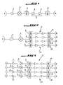
- a communications payload consists of a number of transponders the functional block diagram of which is given in figure 1 .
- a transponder comprises an uplink antenna 1, a low noise amplifier (LNA)2, a converter 3 an input filter or demultiplexer 4, an amplification chain 5 including a channel amplifier 6 and a high power amplifier (HPA) 7, an output filter or multiplexer 8 and a downlink antenna 9.
- LNA low noise amplifier
- HPA high power amplifier
- Figures 2 and 3 show payload architectures to which the invention is specifically applicable.
- the uplink antenna 1, the low noise amplifier 2 and the converter 3 are shared between four transponders.
- the input filter or demultiplexer 4 splits the input into the four transponder channels with bandwidth dedicated to each channel and each is processed by an amplification chain 5 which typically includes the channel amplifier 6 and the high power amplifier (HPA) 7.
- Each channel has its own output filter 8 and a downlink antenna 9. Accordingly, the uplink service area is common to all transponders, but the downlink service areas differ for the transponders.
- both the uplink service area and the downlink service area differ for the different transponders. It could also include a connectivity matrix to allow interconnections between the different coverages.
- the high power amplifier (HPA) 7 represents an important resource that is heavy, dissipate a considerable amount of heat and consumes most of the DC power in the payload. It is consequently a dimensioning factor of the satellite. It is important to use these resources efficiently. This is the object of the present invention. Indeed, since the power of a transponder cannot be increased beyond the maximum power of the high power amplifier, the latter is to be dimensioned for the maximum (peak) power envisaged. Additionally power not used by the high power amplifier of a transponder cannot be allocated to another which may require extra power. The capacity of a transponder is accordingly limited by the maximum power of the high power amplifiers which implies that, in general, the total power of the HPAs, as a whole, is underutilised.
- An aspect of the invention is to eliminate this disadvantage in order to enable the transmission of power greater than the maximum power of a transponder high power amplifier and to fully utilise the on board resources.
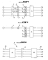
- the figures 4 and 5 show the payload architectures proposed for this purpose particularly suitable for the architectures depicted on figures respectively 2 and 3.
- the payload comprises a multiport amplifier (MPA) 11 such as the one known as Butler amplifier.
- MPA multiport amplifier
- Such a multiport amplifier 11 comprises, as shown on figure 6 , an input Butler matrix 12 which comprises in accordance to the example of the payload structures on figures 4 and 5 four inputs 13a, b, c, d, a bank of four high power amplifiers 14 and an output Butler matrix 15 with four outputs 16a,b,c,d.
- the principle of the multiport amplifier 11 is that a signal at an input port for instance 13a will be split in the input Butler Matrix 12 in amplitude with the appropriate phasing such that all amplifiers 14 will amplify an equal part of the signal.
- the signals from all of the high power amplifiers 14 are then combined by the output Butler Matrix 15 such that the vectorial addition of the signals produce an output at for instance port 16a and ideally nothing at the ports 16b,c,d.
- an input at input port 13b produces an output only at port 16b, an input signal at input port 13c, an output only at output port 16c and an input signal at input port 13d, an output only at output port 16d.
- the total radio frequency (RF) power of the multiport amplifier is determined by the total RF power available for all the high power amplifiers 14.
- the Butler input Matrix 12 represents a passive network which processes the signal entering one of the input ports 13 and simultaneously produces on each of its output ports a signal with equal power and a specific phase distribution.
- each transponder is associated to one high power amplifier, in the shown example of a payload system, a number of four transponders is associated to four shared high power amplifiers in a multiport amplifier.
- the maximum power in the multiport amplifier is fixed but since this is now associated to four transponders, there is a pooling effect. Power can be assigned to each transponder according to the needs and the power not used by some transponder can be assigned to others as long as the total shared power does not exceed the rating of the multiport amplifier.
- the use of the multiport amplifier offers an efficient way to manage the resources of the payload according to the operational requirements.
- the high power amplifier is not dimensioned for the worst case power required but for the total requirement of a number of transponders. This gives an operational flexibility normally not available where the dimensioning is performed on the maximum requirement on a per transponder basis with the associated inefficiency rather than on the total power average over the number of transponders employing the multiport amplifier.
- the channel amplifier 6 it is placed in these configurations at the multiport amplifier input.
- the channel amplifier can be used to control the drive to the specific multiport amplifier input rather than the specific high power amplifier. Changing the power requirement for a given signal can thus be achieved either by reducing the power from the earth station uplinking the signal or by reducing the gain of the appropriate channel amplifier by telecommand.
- the channel amplifiers are not shown in figure 5 .
- the invention such as disclosed here above can be applied to a broadcasting system wherein the satellite is broadcasting over a number of countries.
- the architecture of such a broadcasting system is the one shown on figure 5 with the downlinks each covering a different country for instance Germany, Spain, France, Italy, Tru and the United Kingdom.
- the communication system according to the invention has important advantages. Full connectivity and selectivity are possible sharing the power amongst the transponders on a service area or service areas with no impact on the output network.
- the output selectivity network is completely unnecessary in this architecture yet the selectivity is enhanced.
- one transponder is provided per service area but this need not be the case. This is an extremely powerful operational feature which is otherwise too complicated to implement with an associated strong mass and cost impact.
- OMUX output multiplexer
- the output flexibility is further enhanced since there are no specificities related to the frequency plan. This opens opportunities that are normally not yet possible with a conventional payload.
- any number of transponders of the given set can be activated with the full multiport amplifier power allocation with no impact on the output network.
- the available power can be efficiently divided amongst transponders. This is an extremely powerful operational feature that is otherwise too complicated if not impossible to implement with an associated strong mass and expensive.
- the output losses remain minimal despite the operational flexibility ensuring that as much as possible of the multipower amplifier power is usefully employed. This is important in terms of the performance and the associated financial upside. Since countries have different areas, the antenna gain associated with the service areas is different.
- Using the multiport amplifier concept allows compensation such that the performance on each employed service area is set to be equal if required or individually set to the required level. If equal performance is required, the multiport amplifier allows the increase of performance of the weakest service area which would otherwise be impossible to achieve.
- the multiport amplifier also enhances reliability since the power available could exceed that required tolerating high power amplifier failure without interruption of service. This is an interesting operational and commercial feature that is not normally possible with a conventional payload.
- the Communiation System according to the invention is furthermore advantageously applicable to a Broadband System with a large multi-spot service area.
- the total RF power for spot sharing the multiport amplifier is defined and can be shared in orbit among the corresponding spots.
- This concept provides operational flexibility such that the given power can be split between the spots of the associated multiport amplifier to cater for the operational variation of the capacity requirement.
- the multiport amplifier is used to provide capacity where and when required. If one spot requires more capacity than another spot or other spots are used below average capacity, then capacity can be diverted to the spot requiring the extra capacity.
- the power allocation for a transponder can exceed the power available from the equivalent power amplifier in a multiport amplifier, if and when necessary. This is not possible in a classical payload.
- the flexibility to allocate the full resources between a number of transponders in orbit is a relatively easy feature to accomplish with a multiport amplifier which, in general, is too complicated to implement with a conventional payload.
- the multiport amplifier concept has the advantages that it eases the design of the satellite considerably, that it eases the business case in the planning stations because of the operational flexibility and larger range of operational scenarios that the system can cater for, and that it enhances the operational flexibility in orbit during the satellite life time due to changes of the market and commercial developments that could be impossible to foresee before the satellite definition phase.
Landscapes
- Engineering & Computer Science (AREA)
- Physics & Mathematics (AREA)
- Astronomy & Astrophysics (AREA)
- Aviation & Aerospace Engineering (AREA)
- General Physics & Mathematics (AREA)
- Computer Networks & Wireless Communication (AREA)
- Signal Processing (AREA)
- Amplifiers (AREA)
- Radio Relay Systems (AREA)
Claims (4)
- Système de charge utile pour satellites comprenant une pluralité de dispositifs à transpondeurs comportant chacun une section d'entrée incluant des moyens d'antenne en liaison montante (1) recevant à partir d'au moins une zone de service de liaison montante, un moyen d'amplificateur de bruit faible (2), un moyen de conversion (3) et une section de sortie incluant un moyen de filtrage d'entrée (4), un moyen d'amplificateurs haute puissance et des moyens d'antenne en liaison descendante (9) émettant vers de multiples zones de service de liaison descendante, dans lequel au moins une partie des transpondeurs partagent leur moyen d'amplificateur haute puissance dans la mesure où ladite partie de transpondeurs comprend un amplificateur multiport (11) incluant des amplificateurs de canal (6), une matrice Butler d'entrée (12) avec une entrée pour chaque transpondeur de ladite partie de transpondeurs, chaque entrée acceptant un signal, une banque d'amplificateurs haute puissance (14), dont chacun est destiné à un transpondeur de ladite partie de transpondeurs, les amplificateurs haute puissance de chaque transpondeur de ladite partie de transpondeurs présentant une puissance maximale inférieure à la puissance totale qui peut être transmise par la charge utile, et une matrice Butler de sortie (15) qui rassemble les composantes de chaque signal au niveau d'un port de sortie donné de la matrice Butler de sortie, chaque signal d'entrée au niveau de ladite partie de transpondeurs étant divisé dans la matrice Butler d'entrée (12) en amplitude avec la mise en phase appropriée, de sorte que tous les amplificateurs (14) amplifieront une partie égale du signal, caractérisé en ce que les amplificateurs de canal (6) sont placés au niveau d'entrées d'amplificateur multiport (11) respectives, et en ce que les moyens d'antenne en liaison descendante (9) sont placés au niveau de sorties d'amplificateur multiport respectives, moyennant quoi chaque sortie de l'amplificateur multiport est associée à une différente zone de service de liaison descendante, sans utiliser un multiplexeur de sortie intermédiaire ou un réseau de sélectivité de sortie pour la sélection de zones de service de liaison descendante.
- Système de charge utile selon la revendication 1, caractérisé en ce que la section d'entrée et la section de sortie diffèrent pour les différents transpondeurs.
- Système de charge utile selon la revendication 1, caractérisé en ce que la section d'entrée et la section de sortie diffèrent pour les différents transpondeurs et la puissance de sortie peut être divisée inégalement entre les différents moyens d'antenne en liaison descendante au moyen des amplificateurs de canal.
- Système de charge utile selon la revendication 1, caractérisé en ce que la section d'entrée et la section de sortie diffèrent pour les différents transpondeurs et la puissance de sortie peut être divisée inégalement entre les différentes parties de transpondeurs au moyen des amplificateurs de canal (6).
Priority Applications (3)
| Application Number | Priority Date | Filing Date | Title |
|---|---|---|---|
| EP06291514A EP1906557B1 (fr) | 2006-09-26 | 2006-09-26 | Système de charge utile pour satellites |
| ES06291514T ES2398702T3 (es) | 2006-09-26 | 2006-09-26 | Sistema de carga útil para satélites |
| US11/860,648 US8340573B2 (en) | 2006-09-26 | 2007-09-25 | Payload system for satellites |
Applications Claiming Priority (1)
| Application Number | Priority Date | Filing Date | Title |
|---|---|---|---|
| EP06291514A EP1906557B1 (fr) | 2006-09-26 | 2006-09-26 | Système de charge utile pour satellites |
Publications (2)
| Publication Number | Publication Date |
|---|---|
| EP1906557A1 EP1906557A1 (fr) | 2008-04-02 |
| EP1906557B1 true EP1906557B1 (fr) | 2012-11-07 |
Family
ID=37708205
Family Applications (1)
| Application Number | Title | Priority Date | Filing Date |
|---|---|---|---|
| EP06291514A Not-in-force EP1906557B1 (fr) | 2006-09-26 | 2006-09-26 | Système de charge utile pour satellites |
Country Status (3)
| Country | Link |
|---|---|
| US (1) | US8340573B2 (fr) |
| EP (1) | EP1906557B1 (fr) |
| ES (1) | ES2398702T3 (fr) |
Families Citing this family (3)
| Publication number | Priority date | Publication date | Assignee | Title |
|---|---|---|---|---|
| FR2942775B1 (fr) * | 2009-03-05 | 2011-03-25 | Astrium Sas | Vehicule spatial muni d'un systeme d'amplification et procede d'equilibrage |
| US8494445B2 (en) * | 2010-02-03 | 2013-07-23 | Viasat, Inc. | Flexible coverage areas for forward link signals in a spot beam satellite communication system |
| US10063294B2 (en) | 2014-02-13 | 2018-08-28 | Commscope Technologies Llc | Spatial separation sub-system for supporting multiple-input/multiple-output operations in distributed antenna systems |
Citations (1)
| Publication number | Priority date | Publication date | Assignee | Title |
|---|---|---|---|---|
| US6397039B1 (en) * | 1998-09-14 | 2002-05-28 | Space Systems/Loral, Inc. | Satellite communication system using multiple ground station RF power control in a single downlink beam |
Family Cites Families (12)
| Publication number | Priority date | Publication date | Assignee | Title |
|---|---|---|---|---|
| US3917998A (en) * | 1973-11-02 | 1975-11-04 | Communications Satellite Corp | Butler matrix transponder |
| FR2652452B1 (fr) * | 1989-09-26 | 1992-03-20 | Europ Agence Spatiale | Dispositif d'alimentation d'une antenne a faisceaux multiples. |
| US5289193A (en) * | 1990-11-29 | 1994-02-22 | Alcatel Espace | Reconfigurable transmission antenna |
| US5574967A (en) * | 1994-01-11 | 1996-11-12 | Ericsson Ge Mobile Communications, Inc. | Waste energy control and management in power amplifiers |
| JPH08251094A (ja) * | 1995-03-15 | 1996-09-27 | Hitachi Ltd | 衛星通信システム及び方法 |
| US5675285A (en) * | 1995-12-21 | 1997-10-07 | Lucent Technologies Inc. | Multichannel predistortion linearizer for multiple amplifiers with multiple antennas |
| FR2762728B1 (fr) * | 1997-04-24 | 1999-05-28 | Alsthom Cge Alcatel | Dispositif a amplificateurs de puissance a faible degradation en cas de pannes |
| US6438354B2 (en) * | 1998-12-23 | 2002-08-20 | Hughes Electronics Corporation | Reconfigurable satellite and antenna coverage communications backup capabilities |
| US20030095513A1 (en) * | 1999-12-15 | 2003-05-22 | Nortel Networks Corporation | Traffic management system and method for multi-carrier CDMA wireless networks |
| US20030134595A1 (en) * | 2002-01-11 | 2003-07-17 | Dicamillo Nicholas F. | Optimization of eirp via efficient redundancy pooling concepts |
| KR100703337B1 (ko) * | 2002-07-13 | 2007-04-03 | 삼성전자주식회사 | 이동통신 시스템에서 적응 방식의 전력 풀링 장치 및 방법 |
| FR2857524B1 (fr) * | 2003-07-11 | 2005-09-23 | Cit Alcatel | Dispositif d'amplification pour satellite |
-
2006
- 2006-09-26 EP EP06291514A patent/EP1906557B1/fr not_active Not-in-force
- 2006-09-26 ES ES06291514T patent/ES2398702T3/es active Active
-
2007
- 2007-09-25 US US11/860,648 patent/US8340573B2/en not_active Expired - Fee Related
Patent Citations (1)
| Publication number | Priority date | Publication date | Assignee | Title |
|---|---|---|---|---|
| US6397039B1 (en) * | 1998-09-14 | 2002-05-28 | Space Systems/Loral, Inc. | Satellite communication system using multiple ground station RF power control in a single downlink beam |
Also Published As
| Publication number | Publication date |
|---|---|
| US8340573B2 (en) | 2012-12-25 |
| EP1906557A1 (fr) | 2008-04-02 |
| US20080076350A1 (en) | 2008-03-27 |
| ES2398702T3 (es) | 2013-03-21 |
Similar Documents
| Publication | Publication Date | Title |
|---|---|---|
| EP3231085B1 (fr) | Charge utile numérique ayant des amplificateurs de puissance élevée variable | |
| EP0624008B1 (fr) | Charge utile d'un satellite pour un système de communication mobile | |
| US4879711A (en) | Satellite communications system employing frequency reuse | |
| EP2442460B1 (fr) | Zones de couverture flexibles pour signaux de liaison retour dans un système de communication satellite à faisceau étroit | |
| US6496682B2 (en) | Satellite communication system employing unique spot beam antenna design | |
| US11699850B2 (en) | Method and apparatus for beam steering and switching | |
| JP2003249884A (ja) | 柔軟性ハブ−スポーク衛星通信ネットワークを実装するための装置および方法 | |
| EP3132494B1 (fr) | Architecture de charge utile de satellite à large bande | |
| EP1328073A2 (fr) | Implémentation d'une charge utile à fréquence intermédiaire | |
| US6397039B1 (en) | Satellite communication system using multiple ground station RF power control in a single downlink beam | |
| CN117256110A (zh) | 用于在波束成形系统和卫星的操作模式之间切换的技术 | |
| EP1906557B1 (fr) | Système de charge utile pour satellites | |
| US7768956B2 (en) | Method for the optimization of the payload of a multispot telecommunication satellite | |
| US20030134595A1 (en) | Optimization of eirp via efficient redundancy pooling concepts | |
| US6633745B1 (en) | Satellite cluster comprising a plurality of modular satellites | |
| US7256735B2 (en) | Satellite amplifier system | |
| US11888578B2 (en) | Modular channelizer | |
| EP1328074A2 (fr) | Méchanisme de commutation pour liaison descendante dans un satellite | |
| Ueba et al. | Progress in and prospects of on-board communication equipment technologies for communications satellites in Japan | |
| US20160301463A1 (en) | Broadband satellite payload architecture | |
| Thomas | Flexibility in high throughput satellites | |
| Anzalchi et al. | Generic flexible payload technology for enhancing in-orbit satellite payload flexibility | |
| Lutz et al. | Satellite Technology | |
| Belanger et al. | The communications payload of the MSAT spacecraft | |
| Siess et al. | Odyssey communication system |
Legal Events
| Date | Code | Title | Description |
|---|---|---|---|
| PUAI | Public reference made under article 153(3) epc to a published international application that has entered the european phase |
Free format text: ORIGINAL CODE: 0009012 |
|
| AK | Designated contracting states |
Kind code of ref document: A1 Designated state(s): AT BE BG CH CY CZ DE DK EE ES FI FR GB GR HU IE IS IT LI LT LU LV MC NL PL PT RO SE SI SK TR |
|
| AX | Request for extension of the european patent |
Extension state: AL BA HR MK YU |
|
| 17P | Request for examination filed |
Effective date: 20080929 |
|
| 17Q | First examination report despatched |
Effective date: 20081030 |
|
| AKX | Designation fees paid |
Designated state(s): AT BE BG CH CY CZ DE DK EE ES FI FR GB GR HU IE IS IT LI LT LU LV MC NL PL PT RO SE SI SK TR |
|
| GRAP | Despatch of communication of intention to grant a patent |
Free format text: ORIGINAL CODE: EPIDOSNIGR1 |
|
| GRAS | Grant fee paid |
Free format text: ORIGINAL CODE: EPIDOSNIGR3 |
|
| GRAA | (expected) grant |
Free format text: ORIGINAL CODE: 0009210 |
|
| AK | Designated contracting states |
Kind code of ref document: B1 Designated state(s): AT BE BG CH CY CZ DE DK EE ES FI FR GB GR HU IE IS IT LI LT LU LV MC NL PL PT RO SE SI SK TR |
|
| REG | Reference to a national code |
Ref country code: GB Ref legal event code: FG4D |
|
| REG | Reference to a national code |
Ref country code: CH Ref legal event code: EP Ref country code: AT Ref legal event code: REF Ref document number: 583359 Country of ref document: AT Kind code of ref document: T Effective date: 20121115 |
|
| REG | Reference to a national code |
Ref country code: IE Ref legal event code: FG4D |
|
| REG | Reference to a national code |
Ref country code: DE Ref legal event code: R096 Ref document number: 602006032888 Country of ref document: DE Effective date: 20130103 |
|
| REG | Reference to a national code |
Ref country code: SE Ref legal event code: TRGR |
|
| REG | Reference to a national code |
Ref country code: AT Ref legal event code: MK05 Ref document number: 583359 Country of ref document: AT Kind code of ref document: T Effective date: 20121107 |
|
| REG | Reference to a national code |
Ref country code: ES Ref legal event code: FG2A Ref document number: 2398702 Country of ref document: ES Kind code of ref document: T3 Effective date: 20130321 |
|
| REG | Reference to a national code |
Ref country code: NL Ref legal event code: VDEP Effective date: 20121107 |
|
| REG | Reference to a national code |
Ref country code: LT Ref legal event code: MG4D |
|
| PG25 | Lapsed in a contracting state [announced via postgrant information from national office to epo] |
Ref country code: NL Free format text: LAPSE BECAUSE OF FAILURE TO SUBMIT A TRANSLATION OF THE DESCRIPTION OR TO PAY THE FEE WITHIN THE PRESCRIBED TIME-LIMIT Effective date: 20121107 Ref country code: LT Free format text: LAPSE BECAUSE OF FAILURE TO SUBMIT A TRANSLATION OF THE DESCRIPTION OR TO PAY THE FEE WITHIN THE PRESCRIBED TIME-LIMIT Effective date: 20121107 Ref country code: IS Free format text: LAPSE BECAUSE OF FAILURE TO SUBMIT A TRANSLATION OF THE DESCRIPTION OR TO PAY THE FEE WITHIN THE PRESCRIBED TIME-LIMIT Effective date: 20130307 Ref country code: FI Free format text: LAPSE BECAUSE OF FAILURE TO SUBMIT A TRANSLATION OF THE DESCRIPTION OR TO PAY THE FEE WITHIN THE PRESCRIBED TIME-LIMIT Effective date: 20121107 |
|
| PG25 | Lapsed in a contracting state [announced via postgrant information from national office to epo] |
Ref country code: LV Free format text: LAPSE BECAUSE OF FAILURE TO SUBMIT A TRANSLATION OF THE DESCRIPTION OR TO PAY THE FEE WITHIN THE PRESCRIBED TIME-LIMIT Effective date: 20121107 Ref country code: PT Free format text: LAPSE BECAUSE OF FAILURE TO SUBMIT A TRANSLATION OF THE DESCRIPTION OR TO PAY THE FEE WITHIN THE PRESCRIBED TIME-LIMIT Effective date: 20130307 Ref country code: BE Free format text: LAPSE BECAUSE OF FAILURE TO SUBMIT A TRANSLATION OF THE DESCRIPTION OR TO PAY THE FEE WITHIN THE PRESCRIBED TIME-LIMIT Effective date: 20121107 Ref country code: PL Free format text: LAPSE BECAUSE OF FAILURE TO SUBMIT A TRANSLATION OF THE DESCRIPTION OR TO PAY THE FEE WITHIN THE PRESCRIBED TIME-LIMIT Effective date: 20121107 Ref country code: SI Free format text: LAPSE BECAUSE OF FAILURE TO SUBMIT A TRANSLATION OF THE DESCRIPTION OR TO PAY THE FEE WITHIN THE PRESCRIBED TIME-LIMIT Effective date: 20121107 Ref country code: GR Free format text: LAPSE BECAUSE OF FAILURE TO SUBMIT A TRANSLATION OF THE DESCRIPTION OR TO PAY THE FEE WITHIN THE PRESCRIBED TIME-LIMIT Effective date: 20130208 |
|
| PG25 | Lapsed in a contracting state [announced via postgrant information from national office to epo] |
Ref country code: AT Free format text: LAPSE BECAUSE OF FAILURE TO SUBMIT A TRANSLATION OF THE DESCRIPTION OR TO PAY THE FEE WITHIN THE PRESCRIBED TIME-LIMIT Effective date: 20121107 |
|
| PG25 | Lapsed in a contracting state [announced via postgrant information from national office to epo] |
Ref country code: DK Free format text: LAPSE BECAUSE OF FAILURE TO SUBMIT A TRANSLATION OF THE DESCRIPTION OR TO PAY THE FEE WITHIN THE PRESCRIBED TIME-LIMIT Effective date: 20121107 Ref country code: BG Free format text: LAPSE BECAUSE OF FAILURE TO SUBMIT A TRANSLATION OF THE DESCRIPTION OR TO PAY THE FEE WITHIN THE PRESCRIBED TIME-LIMIT Effective date: 20130207 Ref country code: SK Free format text: LAPSE BECAUSE OF FAILURE TO SUBMIT A TRANSLATION OF THE DESCRIPTION OR TO PAY THE FEE WITHIN THE PRESCRIBED TIME-LIMIT Effective date: 20121107 Ref country code: CZ Free format text: LAPSE BECAUSE OF FAILURE TO SUBMIT A TRANSLATION OF THE DESCRIPTION OR TO PAY THE FEE WITHIN THE PRESCRIBED TIME-LIMIT Effective date: 20121107 Ref country code: EE Free format text: LAPSE BECAUSE OF FAILURE TO SUBMIT A TRANSLATION OF THE DESCRIPTION OR TO PAY THE FEE WITHIN THE PRESCRIBED TIME-LIMIT Effective date: 20121107 |
|
| PG25 | Lapsed in a contracting state [announced via postgrant information from national office to epo] |
Ref country code: RO Free format text: LAPSE BECAUSE OF FAILURE TO SUBMIT A TRANSLATION OF THE DESCRIPTION OR TO PAY THE FEE WITHIN THE PRESCRIBED TIME-LIMIT Effective date: 20121107 |
|
| PLBE | No opposition filed within time limit |
Free format text: ORIGINAL CODE: 0009261 |
|
| STAA | Information on the status of an ep patent application or granted ep patent |
Free format text: STATUS: NO OPPOSITION FILED WITHIN TIME LIMIT |
|
| 26N | No opposition filed |
Effective date: 20130808 |
|
| PG25 | Lapsed in a contracting state [announced via postgrant information from national office to epo] |
Ref country code: CY Free format text: LAPSE BECAUSE OF FAILURE TO SUBMIT A TRANSLATION OF THE DESCRIPTION OR TO PAY THE FEE WITHIN THE PRESCRIBED TIME-LIMIT Effective date: 20121107 |
|
| REG | Reference to a national code |
Ref country code: DE Ref legal event code: R097 Ref document number: 602006032888 Country of ref document: DE Effective date: 20130808 |
|
| PG25 | Lapsed in a contracting state [announced via postgrant information from national office to epo] |
Ref country code: MC Free format text: LAPSE BECAUSE OF FAILURE TO SUBMIT A TRANSLATION OF THE DESCRIPTION OR TO PAY THE FEE WITHIN THE PRESCRIBED TIME-LIMIT Effective date: 20121107 |
|
| REG | Reference to a national code |
Ref country code: CH Ref legal event code: PL |
|
| REG | Reference to a national code |
Ref country code: IE Ref legal event code: MM4A |
|
| PG25 | Lapsed in a contracting state [announced via postgrant information from national office to epo] |
Ref country code: CH Free format text: LAPSE BECAUSE OF NON-PAYMENT OF DUE FEES Effective date: 20130930 Ref country code: IE Free format text: LAPSE BECAUSE OF NON-PAYMENT OF DUE FEES Effective date: 20130926 Ref country code: LI Free format text: LAPSE BECAUSE OF NON-PAYMENT OF DUE FEES Effective date: 20130930 |
|
| PG25 | Lapsed in a contracting state [announced via postgrant information from national office to epo] |
Ref country code: HU Free format text: LAPSE BECAUSE OF FAILURE TO SUBMIT A TRANSLATION OF THE DESCRIPTION OR TO PAY THE FEE WITHIN THE PRESCRIBED TIME-LIMIT; INVALID AB INITIO Effective date: 20060926 |
|
| REG | Reference to a national code |
Ref country code: FR Ref legal event code: PLFP Year of fee payment: 10 |
|
| REG | Reference to a national code |
Ref country code: FR Ref legal event code: PLFP Year of fee payment: 11 |
|
| PGFP | Annual fee paid to national office [announced via postgrant information from national office to epo] |
Ref country code: LU Payment date: 20160824 Year of fee payment: 11 |
|
| PGFP | Annual fee paid to national office [announced via postgrant information from national office to epo] |
Ref country code: IT Payment date: 20160826 Year of fee payment: 11 Ref country code: DE Payment date: 20160823 Year of fee payment: 11 Ref country code: GB Payment date: 20160825 Year of fee payment: 11 |
|
| PGFP | Annual fee paid to national office [announced via postgrant information from national office to epo] |
Ref country code: FR Payment date: 20160822 Year of fee payment: 11 Ref country code: SE Payment date: 20160825 Year of fee payment: 11 |
|
| PGFP | Annual fee paid to national office [announced via postgrant information from national office to epo] |
Ref country code: ES Payment date: 20160824 Year of fee payment: 11 Ref country code: TR Payment date: 20160905 Year of fee payment: 11 |
|
| REG | Reference to a national code |
Ref country code: DE Ref legal event code: R119 Ref document number: 602006032888 Country of ref document: DE |
|
| REG | Reference to a national code |
Ref country code: SE Ref legal event code: EUG |
|
| GBPC | Gb: european patent ceased through non-payment of renewal fee |
Effective date: 20170926 |
|
| PG25 | Lapsed in a contracting state [announced via postgrant information from national office to epo] |
Ref country code: LU Free format text: LAPSE BECAUSE OF NON-PAYMENT OF DUE FEES Effective date: 20170926 |
|
| REG | Reference to a national code |
Ref country code: FR Ref legal event code: ST Effective date: 20180531 |
|
| PG25 | Lapsed in a contracting state [announced via postgrant information from national office to epo] |
Ref country code: DE Free format text: LAPSE BECAUSE OF NON-PAYMENT OF DUE FEES Effective date: 20180404 Ref country code: GB Free format text: LAPSE BECAUSE OF NON-PAYMENT OF DUE FEES Effective date: 20170926 |
|
| PG25 | Lapsed in a contracting state [announced via postgrant information from national office to epo] |
Ref country code: FR Free format text: LAPSE BECAUSE OF NON-PAYMENT OF DUE FEES Effective date: 20171002 Ref country code: IT Free format text: LAPSE BECAUSE OF NON-PAYMENT OF DUE FEES Effective date: 20170926 |
|
| REG | Reference to a national code |
Ref country code: ES Ref legal event code: FD2A Effective date: 20181017 |
|
| PG25 | Lapsed in a contracting state [announced via postgrant information from national office to epo] |
Ref country code: ES Free format text: LAPSE BECAUSE OF NON-PAYMENT OF DUE FEES Effective date: 20170927 |
|
| PG25 | Lapsed in a contracting state [announced via postgrant information from national office to epo] |
Ref country code: SE Free format text: LAPSE BECAUSE OF NON-PAYMENT OF DUE FEES Effective date: 20170927 |
|
| PG25 | Lapsed in a contracting state [announced via postgrant information from national office to epo] |
Ref country code: TR Free format text: LAPSE BECAUSE OF NON-PAYMENT OF DUE FEES Effective date: 20170926 |