EP0731880B1 - Einrichtung zur verhinderung von unterwasserwirbeln an pumpeneinläufen - Google Patents
Einrichtung zur verhinderung von unterwasserwirbeln an pumpeneinläufen Download PDFInfo
- Publication number
- EP0731880B1 EP0731880B1 EP95900701A EP95900701A EP0731880B1 EP 0731880 B1 EP0731880 B1 EP 0731880B1 EP 95900701 A EP95900701 A EP 95900701A EP 95900701 A EP95900701 A EP 95900701A EP 0731880 B1 EP0731880 B1 EP 0731880B1
- Authority
- EP
- European Patent Office
- Prior art keywords
- rib
- inlet
- base
- inlet chamber
- pump
- Prior art date
- Legal status (The legal status is an assumption and is not a legal conclusion. Google has not performed a legal analysis and makes no representation as to the accuracy of the status listed.)
- Expired - Lifetime
Links
- 238000005192 partition Methods 0.000 description 6
- 230000015572 biosynthetic process Effects 0.000 description 4
- 230000002265 prevention Effects 0.000 description 2
- 230000003068 static effect Effects 0.000 description 2
- WYTGDNHDOZPMIW-RCBQFDQVSA-N alstonine Natural products C1=CC2=C3C=CC=CC3=NC2=C2N1C[C@H]1[C@H](C)OC=C(C(=O)OC)[C@H]1C2 WYTGDNHDOZPMIW-RCBQFDQVSA-N 0.000 description 1
- 238000005253 cladding Methods 0.000 description 1
- 230000006378 damage Effects 0.000 description 1
- 230000006735 deficit Effects 0.000 description 1
- 230000000694 effects Effects 0.000 description 1
- 238000002474 experimental method Methods 0.000 description 1
- 239000007788 liquid Substances 0.000 description 1
- JTJMJGYZQZDUJJ-UHFFFAOYSA-N phencyclidine Chemical class C1CCCCN1C1(C=2C=CC=CC=2)CCCCC1 JTJMJGYZQZDUJJ-UHFFFAOYSA-N 0.000 description 1
- 230000000630 rising effect Effects 0.000 description 1
- 239000004576 sand Substances 0.000 description 1
- 230000001629 suppression Effects 0.000 description 1
- 210000000689 upper leg Anatomy 0.000 description 1
- 238000011144 upstream manufacturing Methods 0.000 description 1
Images
Classifications
-
- F—MECHANICAL ENGINEERING; LIGHTING; HEATING; WEAPONS; BLASTING
- F04—POSITIVE - DISPLACEMENT MACHINES FOR LIQUIDS; PUMPS FOR LIQUIDS OR ELASTIC FLUIDS
- F04D—NON-POSITIVE-DISPLACEMENT PUMPS
- F04D29/00—Details, component parts, or accessories
- F04D29/40—Casings; Connections of working fluid
- F04D29/42—Casings; Connections of working fluid for radial or helico-centrifugal pumps
- F04D29/426—Casings; Connections of working fluid for radial or helico-centrifugal pumps especially adapted for liquid pumps
- F04D29/4273—Casings; Connections of working fluid for radial or helico-centrifugal pumps especially adapted for liquid pumps suction eyes
-
- F—MECHANICAL ENGINEERING; LIGHTING; HEATING; WEAPONS; BLASTING
- F04—POSITIVE - DISPLACEMENT MACHINES FOR LIQUIDS; PUMPS FOR LIQUIDS OR ELASTIC FLUIDS
- F04D—NON-POSITIVE-DISPLACEMENT PUMPS
- F04D29/00—Details, component parts, or accessories
- F04D29/66—Combating cavitation, whirls, noise, vibration or the like; Balancing
- F04D29/68—Combating cavitation, whirls, noise, vibration or the like; Balancing by influencing boundary layers
- F04D29/688—Combating cavitation, whirls, noise, vibration or the like; Balancing by influencing boundary layers especially adapted for liquid pumps
-
- F—MECHANICAL ENGINEERING; LIGHTING; HEATING; WEAPONS; BLASTING
- F04—POSITIVE - DISPLACEMENT MACHINES FOR LIQUIDS; PUMPS FOR LIQUIDS OR ELASTIC FLUIDS
- F04D—NON-POSITIVE-DISPLACEMENT PUMPS
- F04D29/00—Details, component parts, or accessories
- F04D29/70—Suction grids; Strainers; Dust separation; Cleaning
- F04D29/708—Suction grids; Strainers; Dust separation; Cleaning specially for liquid pumps
Definitions
- centrifugal pumps suck the medium via a vertically arranged inlet from a Inlet chamber, which is also referred to as a pump sump (KSB centrifugal pump lexicon, 1989, pages 88 and 89).
- a such inlet chamber mainly serves to improve the Inlet conditions to the centrifugal pump, with it one is possible balanced, vortex-free inflow sought. This is before especially for specific high-speed pumps with propeller or Semi-axial wheel indispensable because this is due to interference in the Inflow react immediately.
- the actual, tubular pump inlet is usually an inlet nozzle, also called a suction bell, upstream.
- the inlet nozzle eliminates irregularities in the velocity distribution of the incoming liquid smoothed.
- cones or crosses arranged in the pump inlet recommended.
- JP-A-61-155699 In a known device for preventing Vortex formation for a pump with a vertical shaft (JP-A-61-155699) becomes an L-shaped partition suggested that from below the pump inlet running part merges into one on the rear wall of the Inlet chamber arranged part up to the height lowered ceiling of the inlet chamber is sufficient. To avoid air-drawing surface vortex is one below provided vortex protection strip attached to the ceiling.
- Partitions, baffles and plates or vortex protection strips a special kind of eddies are not capable of avoid the surfaces on the inlet chamber Floor and wall, which arise as ground or underwater vortices be designated. That on the floor or wall surface bound end of such a vortex moves in one certain area back and forth while the other end in the Pump pulls in. Since the rotational speed at the center of the Underwater vortex is very large, the static drops there Pressure below the vapor pressure of the medium, with the result that the vortex forms as a steam-filled hose.
- the aim of the invention is to prevent the Underwater whirling effort to a minimum to reduce. This is achieved through a facility that is in the Claim 1 is shown with their design limits.
- the diameter (D) given here as a reference is not the diameter of the inlet nozzle, but that of the above the Inlet nozzle located tubular pump inlet.
- the invention is based on the following finding:
- Claim 2 calls one as an additional device rib arranged on the rear wall of the inlet chamber, the height of which and width within that for the bottom rib applicable limit values remain. According to claim 3 can the bottom and wall ribs into a single, L-shaped designed rib can be summarized.
- the rib can also, as in claim 5 set out to run at an angle to the main stream.
- the rib Incidentally, does not have to form a completely straight line; their course can deviate from a straight line according to claim 6. This can inter alia mean that the rib, as in claim 7 taught from two at an angle to each other There is thighs or that according to claim 8 in one Curve runs. In claim 9 it is pointed out that the cross section of the rib change over its course can.
- the invention is based on various exemplary embodiments explained in more detail.
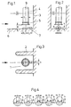
- the inlet chamber 1 shown in FIGS. 1 to 3 is formed between two side walls 2 and one Rear wall 3. This projects vertically into the inlet chamber 1 arranged suction pipe of a pump inlet 4. At the lower end of the pump inlet 4, which has a diameter D, is one Inlet nozzle 5 is provided.
- a rib 7 which can be made in one piece with the bottom 6 or attached to it as a separate part.
- the cross-sectional shape of the rib 7 is arbitrary.
- the FIG. 4 corresponding to the detail x of FIG. 2 shows only some of the possible forms here. It is essential, however, that all cross sections must remain within predetermined limits for the height h and width b in order to be able to develop their underwater vortex-preventing effect.
- the values related to the diameter D of the pump inlet are: 0.055 ⁇ h / D ⁇ 0.29 0.045 ⁇ b / D ⁇ 0.39.
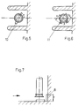
- Height h and width b apply to one on the rear wall 3 arranged rib 8, as shown in FIG. 7.
- a rib 8 is to be expected underwater vortices provided in addition to the rib 7.
- the rib 8 is located on the in the direction of the main stream (each in the drawing indicated by an arrow) offset central axis 9 of the Pump inlet 4.
- the length y of the rib 8 corresponds at least the distance H between the bottom 6 of the inlet chamber 1 and the Inlet opening of the pump inlet 4, which here through the Inlet nozzle 5 is formed.
- the rib 7 runs in a straight line following the main stream Line.
- the ribs 10 and 11 shown in FIGS. 5 and 6 have a different course, but also lead to Desired success: suppression of the floor area emerging underwater vortices.
- the rib-shaped device according to the invention is not closed to be confused with the baffles mentioned at the beginning or Partitions, which are also below the pump inlet are aligned with the mainstream direction, but just a general equalization of the pump inflow cause.
- the main flow is through partitions divided into two areas, each with the for the emergence of underwater vortices applicable boundary conditions occur.
- the baffles form or partitions separate wall areas, on which in turn Underwater vortices can arise.
Landscapes
- Engineering & Computer Science (AREA)
- Mechanical Engineering (AREA)
- General Engineering & Computer Science (AREA)
- Structures Of Non-Positive Displacement Pumps (AREA)
Description
- Fig. 1 bis 3
- eine mit einer erfindungsgemäßen Einrichtung ausgestattete Einlaufkammer in drei Ansichten, in
- Fig. 4
- verschiedene mögliche Querschnittsformen der am Boden oder der Rückwand der Einlaufkammer angeordneten Rippe, in
- Fig. 5 und 6
- Draufsichten auf Einlaufkammern mit am Boden angeordneten Rippen, welche nicht in Richtung des Hauptstromes verlaufen, und in
- Fig. 7
- eine alternative Ausführung der erfindungsgemäßen Einrichtung mit am Boden und der Wand der Einlaufkammer angeordneten Rippen.
Claims (9)
- Einrichtung zur Verhinderung von am Boden (6) und an der Rückwand (3) der Einlaufkammer (1) einer Kreiselpumpe entstehenden Unterwasserwirbeln, mit einer auf dem Boden (6) der Einlaufkammer (1) angeordneten, durch die verlängerte Mittelachse (9) des Pumpeneinlaufs (4) verlaufenden Rippe (7) beliebigen Querschnitts, deren Höhe (h) und Breite (b) und deren beide von der verlängerten Mittelachse (9) des Pumpeneinlaufs (4) ausgehende Erstreckungen (x1, x2) folgende auf den Durchmesser (D) des Pumpeneinlaufs (4) bezogene Werte besitzen:a) 0,055 < h/D < 0,29b) 0,045 < b/D < 0,39c) 0,45 < x1/D < ∞d) 0,45 < x2/D < ∞.
- Einrichtung nach Anspruch 1, mit einer an der Rückwand (3) der Einlaufkammer (1) angeordneten, auf der in Richtung des Hauptstromes versetzten Mittelachse (9) des Pumpeneinlaufs (4) verlaufenden Rippe (8) beliebigen Querschnitts, deren Höhe (h) und Breite (b) innerhalb der für die am Boden (6) angeordnete Rippe (7) geltenden Grenzwerten bleiben, während die Länge (y) etwa dem Abstand (H) zwischen dem Boden (6) der Einlaufkammer (1) und der Eintrittsöffnung (5) des Pumpeneinlaufs (4) entspricht.
- Einrichtung nach den Ansprüchen 1 und 2, mit einer L-förmig gestalteten, auf dem Boden (6) und an der Wand (3) verlaufenden Rippe.
- Einrichtung nach Anspruch 1, mit einer auf dem Boden (6) der Einlaufkammer (1) angeordneten, in Richtung des Hauptstromes verlaufenden Rippe (7).
- Einrichtung nach Anspruch 1, mit einer auf dem Boden (6) der Einlaufkammer (1) angeordneten, in einem Winkel (α) zum Hauptstrom verlaufenden Rippe (10).
- Einrichtung nach Anspruch 1, mit einer auf dem Boden (6) der Einlaufkammer (1) angeordneten Rippe, die einen von einer geraden Linie abweichenden Verlauf besitzt.
- Einrichtung nach Anspruch 6, deren Rippe (11) aus zwei in einem Winkel (β) zueinander stehenden Schenkeln besteht, wobei der zwischen den beiden Schenkeln gebildete Winkel (β) zwischen 90° und 270° liegt.
- Einrichtung nach Anspruch 6, deren Rippe in einer Kurvenlinie verläuft.
- Einrichtung nach Anspruch 1 und 2, mit einer Rippe, deren Querschnitt sich über ihren Verlauf verändert.
Applications Claiming Priority (3)
| Application Number | Priority Date | Filing Date | Title |
|---|---|---|---|
| DE4340711A DE4340711A1 (de) | 1993-11-30 | 1993-11-30 | Einrichtung zur Verhinderung von Unterwasserwirbeln an Pumpeneinläufen |
| DE4340711 | 1993-11-30 | ||
| PCT/EP1994/003720 WO1995015440A1 (de) | 1993-11-30 | 1994-11-10 | Einrichtung zur verhinderung von unterwasserwirbeln an pumpeneinläufen |
Publications (2)
| Publication Number | Publication Date |
|---|---|
| EP0731880A1 EP0731880A1 (de) | 1996-09-18 |
| EP0731880B1 true EP0731880B1 (de) | 1998-07-15 |
Family
ID=6503761
Family Applications (1)
| Application Number | Title | Priority Date | Filing Date |
|---|---|---|---|
| EP95900701A Expired - Lifetime EP0731880B1 (de) | 1993-11-30 | 1994-11-10 | Einrichtung zur verhinderung von unterwasserwirbeln an pumpeneinläufen |
Country Status (4)
| Country | Link |
|---|---|
| EP (1) | EP0731880B1 (de) |
| CN (1) | CN1051359C (de) |
| DE (2) | DE4340711A1 (de) |
| WO (1) | WO1995015440A1 (de) |
Cited By (1)
| Publication number | Priority date | Publication date | Assignee | Title |
|---|---|---|---|---|
| CN105139746A (zh) * | 2015-08-27 | 2015-12-09 | 武汉大学 | 一种泵站进水池漩涡实验台 |
Families Citing this family (8)
| Publication number | Priority date | Publication date | Assignee | Title |
|---|---|---|---|---|
| DE10003517C2 (de) * | 2000-01-27 | 2001-11-22 | Siemens Ag | Betriebsgebäude für eine Anlage und Verfahren zum Betrieb eines Betriebsgebäudes |
| US8784053B2 (en) * | 2010-12-21 | 2014-07-22 | Hamilton Sundstrand Corporation | Fan shield and bearing housing for air cycle machine |
| CN105401616B (zh) * | 2015-12-18 | 2017-07-25 | 江苏省水利工程科技咨询股份有限公司 | 一种开敞式进水池水下异形盖板消涡装置及其方法 |
| CN105697424B (zh) * | 2016-01-19 | 2019-01-08 | 江苏大学 | 一种泵站用防旋涡装置 |
| CN105625557B (zh) * | 2016-01-22 | 2018-01-12 | 赛莱默水处理系统(沈阳)有限公司 | 一体化污水处理泵站 |
| DE202016101589U1 (de) | 2016-03-23 | 2016-04-22 | Homa Pumpenfabrik Gmbh | Einlaufkammer für eine Axialpumpe |
| JP6653204B2 (ja) * | 2016-03-30 | 2020-02-26 | 三菱日立パワーシステムズ株式会社 | 取水ピット及びプラント |
| CN106381832B (zh) * | 2016-09-12 | 2018-04-03 | 河海大学 | 一种集漩涡消涡和发电于一体的实验模拟装置 |
Family Cites Families (4)
| Publication number | Priority date | Publication date | Assignee | Title |
|---|---|---|---|---|
| GB785926A (en) * | 1955-06-03 | 1957-11-06 | Sulzer Ag | Pumping plants |
| DE2137637B2 (de) * | 1971-07-28 | 1977-10-27 | Klein Schanzlin & Becker Ag | Leitvorrichtung fuer einlaufkammern schnellaeufiger pumpen |
| DE2933904C2 (de) * | 1979-08-22 | 1985-03-14 | Klein, Schanzlin & Becker Ag, 6710 Frankenthal | Einlaufkrümmer |
| JPS61155699A (ja) * | 1984-12-27 | 1986-07-15 | Fuji Electric Co Ltd | 立軸ポンプの渦流防止装置 |
-
1993
- 1993-11-30 DE DE4340711A patent/DE4340711A1/de not_active Withdrawn
-
1994
- 1994-11-10 WO PCT/EP1994/003720 patent/WO1995015440A1/de not_active Ceased
- 1994-11-10 CN CN94193425A patent/CN1051359C/zh not_active Expired - Lifetime
- 1994-11-10 EP EP95900701A patent/EP0731880B1/de not_active Expired - Lifetime
- 1994-11-10 DE DE59406462T patent/DE59406462D1/de not_active Expired - Lifetime
Cited By (2)
| Publication number | Priority date | Publication date | Assignee | Title |
|---|---|---|---|---|
| CN105139746A (zh) * | 2015-08-27 | 2015-12-09 | 武汉大学 | 一种泵站进水池漩涡实验台 |
| CN105139746B (zh) * | 2015-08-27 | 2017-06-09 | 武汉大学 | 一种泵站进水池漩涡实验台 |
Also Published As
| Publication number | Publication date |
|---|---|
| CN1051359C (zh) | 2000-04-12 |
| WO1995015440A1 (de) | 1995-06-08 |
| CN1131453A (zh) | 1996-09-18 |
| DE59406462D1 (de) | 1998-08-20 |
| DE4340711A1 (de) | 1995-06-01 |
| EP0731880A1 (de) | 1996-09-18 |
Similar Documents
| Publication | Publication Date | Title |
|---|---|---|
| EP0985098B1 (de) | Kreiselpumpe mit einer einlaufleiteinrichtung | |
| DE202011110549U1 (de) | Vordüse für ein Antriebssystem eines Wasserfahrzeuges zur Verbesserung der Energieeffizienz | |
| DE4340711A1 (de) | Einrichtung zur Verhinderung von Unterwasserwirbeln an Pumpeneinläufen | |
| DE68904169T2 (de) | Uebergangskanal fuer radialverdichter. | |
| DE1194116B (de) | Vorrichtung zum Einfuehren eines Luftstroms durch Ejektorwirkung in einen anderen Luftstrom | |
| EP0449861B1 (de) | Kreiselpumpenlaufrad geringer spezifischer drehzahl | |
| EP1250532B1 (de) | Betriebsgebäude für eine anlage und verfahren zum betrieb eines betriebsgebäudes | |
| EP1616100B1 (de) | Freistrompumpe | |
| DE1262234B (de) | Drehstroemungswirbler zum Abscheiden fester oder fluessiger Teilchen aus Gasen | |
| WO2003001120A1 (de) | Luftbefeuchtungsvorrichtung | |
| DE69601215T2 (de) | Verfahren zum konditionieren einer flüssigkeitsströmung und behandlungsvorrichtung einer flüssigkeitsströmung | |
| DE2903277A1 (de) | Schraubenpumpe, insbesondere zur foerderung von abwasser u.dgl. | |
| DE19618300C2 (de) | Durchströmte Tauchwand | |
| DE4314478A1 (de) | Einlaufgehäuse für Kreiselpumpen | |
| AT284637B (de) | Saugkrümmer für Kreiselpumpen | |
| DE20214291U1 (de) | Rühr-Vorrichtung für hochviskose Medien | |
| DE19960893A1 (de) | Vorrichtung zur Regulierung der Fördermenge von vertikalachsigen Kreiselpumpen | |
| DE2712444A1 (de) | Wirbelkammerventil | |
| AT207088B (de) | Abschirmung von Raumöffnungen durch einen Luftschleier | |
| DE1653786A1 (de) | Saugkruemmer fuer Kreiselpumpen | |
| DE1653786C (de) | Saugkrümmer für Kreiselpumpen | |
| DE7304408U (de) | Venturi-rieselturm mit veraenderlicher engstelle | |
| DE4034301C1 (en) | Appts. for deflecting gas-stream - comprises U=sections placed in entrance of second channel in plane transverse to first channel | |
| DE102017105921A1 (de) | Saugfuß für eine Bodenreinigungsmaschine | |
| EP3306100A1 (de) | Einlaufdüse für einen radialventilator |
Legal Events
| Date | Code | Title | Description |
|---|---|---|---|
| PUAI | Public reference made under article 153(3) epc to a published international application that has entered the european phase |
Free format text: ORIGINAL CODE: 0009012 |
|
| 17P | Request for examination filed |
Effective date: 19960418 |
|
| AK | Designated contracting states |
Kind code of ref document: A1 Designated state(s): DE FR GB NL |
|
| GRAG | Despatch of communication of intention to grant |
Free format text: ORIGINAL CODE: EPIDOS AGRA |
|
| GRAG | Despatch of communication of intention to grant |
Free format text: ORIGINAL CODE: EPIDOS AGRA |
|
| GRAH | Despatch of communication of intention to grant a patent |
Free format text: ORIGINAL CODE: EPIDOS IGRA |
|
| 17Q | First examination report despatched |
Effective date: 19971222 |
|
| GRAH | Despatch of communication of intention to grant a patent |
Free format text: ORIGINAL CODE: EPIDOS IGRA |
|
| GRAA | (expected) grant |
Free format text: ORIGINAL CODE: 0009210 |
|
| AK | Designated contracting states |
Kind code of ref document: B1 Designated state(s): DE FR GB NL |
|
| PG25 | Lapsed in a contracting state [announced via postgrant information from national office to epo] |
Ref country code: NL Free format text: LAPSE BECAUSE OF FAILURE TO SUBMIT A TRANSLATION OF THE DESCRIPTION OR TO PAY THE FEE WITHIN THE PRESCRIBED TIME-LIMIT Effective date: 19980715 Ref country code: FR Free format text: LAPSE BECAUSE OF FAILURE TO SUBMIT A TRANSLATION OF THE DESCRIPTION OR TO PAY THE FEE WITHIN THE PRESCRIBED TIME-LIMIT Effective date: 19980715 |
|
| REF | Corresponds to: |
Ref document number: 59406462 Country of ref document: DE Date of ref document: 19980820 |
|
| GBT | Gb: translation of ep patent filed (gb section 77(6)(a)/1977) |
Effective date: 19980915 |
|
| NLV1 | Nl: lapsed or annulled due to failure to fulfill the requirements of art. 29p and 29m of the patents act | ||
| EN | Fr: translation not filed | ||
| PLBQ | Unpublished change to opponent data |
Free format text: ORIGINAL CODE: EPIDOS OPPO |
|
| PLBI | Opposition filed |
Free format text: ORIGINAL CODE: 0009260 |
|
| 26 | Opposition filed |
Opponent name: ITT FLYGT AB Effective date: 19990315 |
|
| PLBF | Reply of patent proprietor to notice(s) of opposition |
Free format text: ORIGINAL CODE: EPIDOS OBSO |
|
| PLBF | Reply of patent proprietor to notice(s) of opposition |
Free format text: ORIGINAL CODE: EPIDOS OBSO |
|
| PLBO | Opposition rejected |
Free format text: ORIGINAL CODE: EPIDOS REJO |
|
| PLBN | Opposition rejected |
Free format text: ORIGINAL CODE: 0009273 |
|
| STAA | Information on the status of an ep patent application or granted ep patent |
Free format text: STATUS: OPPOSITION REJECTED |
|
| 27O | Opposition rejected |
Effective date: 20000820 |
|
| REG | Reference to a national code |
Ref country code: GB Ref legal event code: IF02 |
|
| PGFP | Annual fee paid to national office [announced via postgrant information from national office to epo] |
Ref country code: DE Payment date: 20131106 Year of fee payment: 20 Ref country code: GB Payment date: 20131120 Year of fee payment: 20 |
|
| REG | Reference to a national code |
Ref country code: DE Ref legal event code: R071 Ref document number: 59406462 Country of ref document: DE |
|
| REG | Reference to a national code |
Ref country code: DE Ref legal event code: R071 Ref document number: 59406462 Country of ref document: DE |
|
| REG | Reference to a national code |
Ref country code: GB Ref legal event code: PE20 Expiry date: 20141109 |
|
| PG25 | Lapsed in a contracting state [announced via postgrant information from national office to epo] |
Ref country code: GB Free format text: LAPSE BECAUSE OF EXPIRATION OF PROTECTION Effective date: 20141109 |