EP0731056B1 - System und Verfahren zur Überwachung und Sicherung des Umfüllvorganges zwischen einem Tankfahrzeug und einem unterirdischen Lagerbehälter - Google Patents
System und Verfahren zur Überwachung und Sicherung des Umfüllvorganges zwischen einem Tankfahrzeug und einem unterirdischen Lagerbehälter Download PDFInfo
- Publication number
- EP0731056B1 EP0731056B1 EP96103614A EP96103614A EP0731056B1 EP 0731056 B1 EP0731056 B1 EP 0731056B1 EP 96103614 A EP96103614 A EP 96103614A EP 96103614 A EP96103614 A EP 96103614A EP 0731056 B1 EP0731056 B1 EP 0731056B1
- Authority
- EP
- European Patent Office
- Prior art keywords
- hose
- filling
- limit value
- value sensor
- electric circuit
- Prior art date
- Legal status (The legal status is an assumption and is not a legal conclusion. Google has not performed a legal analysis and makes no representation as to the accuracy of the status listed.)
- Expired - Lifetime
Links
- 238000000034 method Methods 0.000 title claims abstract description 35
- 239000007788 liquid Substances 0.000 title claims description 17
- 238000012546 transfer Methods 0.000 claims abstract description 53
- 230000008569 process Effects 0.000 claims abstract description 29
- 230000008878 coupling Effects 0.000 claims description 66
- 238000010168 coupling process Methods 0.000 claims description 66
- 238000005859 coupling reaction Methods 0.000 claims description 66
- 238000005429 filling process Methods 0.000 claims description 44
- 235000014676 Phragmites communis Nutrition 0.000 claims description 42
- 239000000446 fuel Substances 0.000 claims description 12
- 239000000945 filler Substances 0.000 claims description 10
- 239000002283 diesel fuel Substances 0.000 claims description 6
- 230000005520 electrodynamics Effects 0.000 claims description 6
- 238000009413 insulation Methods 0.000 claims description 4
- 230000005540 biological transmission Effects 0.000 claims description 3
- 229910001369 Brass Inorganic materials 0.000 claims description 2
- 230000004888 barrier function Effects 0.000 claims description 2
- 239000010951 brass Substances 0.000 claims description 2
- 239000004020 conductor Substances 0.000 claims description 2
- 239000012811 non-conductive material Substances 0.000 claims description 2
- 238000006073 displacement reaction Methods 0.000 claims 32
- 230000003213 activating effect Effects 0.000 claims 4
- 230000003993 interaction Effects 0.000 claims 2
- 244000273256 Phragmites communis Species 0.000 claims 1
- 230000002950 deficient Effects 0.000 abstract 1
- 238000007689 inspection Methods 0.000 abstract 1
- 239000007789 gas Substances 0.000 description 55
- 238000012544 monitoring process Methods 0.000 description 38
- 238000010586 diagram Methods 0.000 description 13
- 230000001133 acceleration Effects 0.000 description 10
- 238000012806 monitoring device Methods 0.000 description 10
- 238000011156 evaluation Methods 0.000 description 6
- 210000000078 claw Anatomy 0.000 description 5
- 238000013461 design Methods 0.000 description 4
- 238000005259 measurement Methods 0.000 description 4
- UHOVQNZJYSORNB-UHFFFAOYSA-N Benzene Chemical compound C1=CC=CC=C1 UHOVQNZJYSORNB-UHFFFAOYSA-N 0.000 description 3
- 230000001419 dependent effect Effects 0.000 description 3
- LFQSCWFLJHTTHZ-UHFFFAOYSA-N Ethanol Chemical compound CCO LFQSCWFLJHTTHZ-UHFFFAOYSA-N 0.000 description 2
- 230000008859 change Effects 0.000 description 2
- 230000007547 defect Effects 0.000 description 2
- 230000005284 excitation Effects 0.000 description 2
- 239000002689 soil Substances 0.000 description 2
- 239000000126 substance Substances 0.000 description 2
- 239000000725 suspension Substances 0.000 description 2
- 239000002253 acid Substances 0.000 description 1
- 150000007513 acids Chemical class 0.000 description 1
- 238000013459 approach Methods 0.000 description 1
- 230000009286 beneficial effect Effects 0.000 description 1
- 239000000356 contaminant Substances 0.000 description 1
- 238000013016 damping Methods 0.000 description 1
- 238000011161 development Methods 0.000 description 1
- 230000000694 effects Effects 0.000 description 1
- 230000005611 electricity Effects 0.000 description 1
- 238000005516 engineering process Methods 0.000 description 1
- 239000003673 groundwater Substances 0.000 description 1
- 239000000383 hazardous chemical Substances 0.000 description 1
- 238000009434 installation Methods 0.000 description 1
- 230000009191 jumping Effects 0.000 description 1
- 239000003350 kerosene Substances 0.000 description 1
- 238000012423 maintenance Methods 0.000 description 1
- 230000007257 malfunction Effects 0.000 description 1
- 239000000463 material Substances 0.000 description 1
- 238000011022 operating instruction Methods 0.000 description 1
- 230000010355 oscillation Effects 0.000 description 1
- 230000002265 prevention Effects 0.000 description 1
- 230000009467 reduction Effects 0.000 description 1
- 238000009420 retrofitting Methods 0.000 description 1
- 238000005070 sampling Methods 0.000 description 1
- 238000001228 spectrum Methods 0.000 description 1
- 238000012549 training Methods 0.000 description 1
- 238000002604 ultrasonography Methods 0.000 description 1
Images






Classifications
-
- B—PERFORMING OPERATIONS; TRANSPORTING
- B67—OPENING, CLOSING OR CLEANING BOTTLES, JARS OR SIMILAR CONTAINERS; LIQUID HANDLING
- B67D—DISPENSING, DELIVERING OR TRANSFERRING LIQUIDS, NOT OTHERWISE PROVIDED FOR
- B67D7/00—Apparatus or devices for transferring liquids from bulk storage containers or reservoirs into vehicles or into portable containers, e.g. for retail sale purposes
- B67D7/06—Details or accessories
- B67D7/32—Arrangements of safety or warning devices; Means for preventing unauthorised delivery of liquid
-
- B—PERFORMING OPERATIONS; TRANSPORTING
- B67—OPENING, CLOSING OR CLEANING BOTTLES, JARS OR SIMILAR CONTAINERS; LIQUID HANDLING
- B67D—DISPENSING, DELIVERING OR TRANSFERRING LIQUIDS, NOT OTHERWISE PROVIDED FOR
- B67D7/00—Apparatus or devices for transferring liquids from bulk storage containers or reservoirs into vehicles or into portable containers, e.g. for retail sale purposes
- B67D7/06—Details or accessories
- B67D7/32—Arrangements of safety or warning devices; Means for preventing unauthorised delivery of liquid
- B67D7/34—Means for preventing unauthorised delivery of liquid
- B67D7/344—Means for preventing unauthorised delivery of liquid by checking a correct coupling or coded information
Definitions
- the invention relates to a system and a method for monitoring and securing the transfer process between a tanker and a particularly underground storage container or another Tanker or between storage containers, at least one Hose using a transfer device with connection fittings, for example. on the tanker to at least one transfer tube, e.g. the storage tank is connectable and the monitoring system with a power supply a circuit forming a decanting device switching level indicator on the storage container.
- the invention further relates to the use of the system.
- a system for monitoring the connection is known from EP 0 330 859 B1 of closable pipes and one between them Pipelines connectable connecting line known.
- the connecting line is designed to be electrically conductive and forms a part of it a closed circuit a monitoring device.
- the Shut-off devices of the pipelines are only by a Control device operable by the monitoring device is activated.
- An emergency stop switch is arranged in the circuit, through which the intrinsically safe circuit when needed can be interrupted. Via resistance or current measurement the closed state of the circuit is defined in Checked time intervals. As long as the pulsed signals to the monitoring device run back, the shut-off devices remain Pipes opened, otherwise they are closed.
- a disadvantage of this known monitoring system is that this system is very prone to failure if it is in the cathedral shaft underground storage container is arranged. Furthermore, with this previously known system can not be identified whether the Couplings are connected media-tight, so that considerable quantities of environmentally hazardous substances can get into the environment. This is caused in particular by the fact that the current flow for monitoring of the hose connection also occurs when the connection flange the connecting cable only loosely on the one to be connected Pipe (filler neck) rests. This known surveillance system therefore emphasizes that the shut-off devices exclusively via the one that can be activated by the monitoring device Control device can be actuated.
- EP-0 330 860 B1 describes a monitoring system for filling or against overfilling a container is known, a PTC resistor the maximum permissible product level in the container detected. Between a filling pipe and a connecting pipe there is an electrically conductive connection line on the container arranged, isolated from the tap and the container is. An electric one is used to monitor the filling process Circuit in which the connecting line and the PTC resistor are connected in series. The PTC thermistor is immersed in the medium in the container, its change in resistance is monitored by a monitoring device detected and the shut-off devices in the Filling pipe closed by a control device after this was activated by the monitoring device.
- the invention has for its object a new system and method for monitoring and securing the transfer process between one Tanker and a storage container of the type mentioned to indicate which is extremely robust and for use in the cathedral shaft as well as in a tanker vehicle under the rough ones given there Operating conditions is suitable, and also inherently fail-safe is, i.e. that if an error occurs in the safe Operating state drops by locking itself and becoming one Failure to release the filling process or to interrupt it leads, furthermore, to the equipment of existing tankers and storage tank systems retrofittable and retrofitting and / or new equipment the operator is reasonable for cost reasons.
- the task is solved with a system for monitoring and Securing the transfer process between a tanker and a Storage container of the type mentioned in the preamble of claim 1 the invention in that at least one of the existing level monitoring system switched on fail-safe working Safety device is provided, which in the event of a fault Transfer process interrupts the circuit of the limit indicator and this switches off the decanting device on the tanker.
- the fail-safe working safety device closes such System elements that are included in the system anyway and fall in the event of system errors, always in the operationally safe state.
- the circuit the limit transmitter and / or its electronics at least one of the Filling hose and / or gas pendulum hose and / or their fittings assigned and with these directly or via mechanical / electrodynamic excitable means interacting additional circuitry which has the circuit of the limit indicator, which arises when the limit switch is connected correctly lasts as long as the filling hose or filling hose and gas pendulum hose correct with their fittings on the storage container side and / or vehicle-side connections connected or not are interrupted, and the circuit breaks as soon as fittings or hoses are not connected correctly, or hoses completely or partially torn off.
- EP 0 330 860 B1 deals with a monitoring system in which the PTC resistor and the connecting line are connected in series in a circuit. This is not the case with the system according to the invention; here the current via the connection lines, i.e. hoses, is only galvanically connected, there are at least two circuits.
- EP 0 330 860 B1 also states that the monitoring device comprises at least one voltage source and functional elements for measuring suitable electrical parameters of the circuit, specifically for detecting the mechanical state of the connecting lines and the fill level. This is also not the case with the new system according to the invention.
- the new method presented here uses a new one Circuit with passive components such as reed sensors or relays existing circuit interrupted or closed. Because of this process the filling process is interrupted or released. This idea does not underlie all known systems and does not emerge from these.
- the system according to the invention and the corresponding system are thus based Procedure based on a functional principle by which when filling underground storage tank of tank vehicles with the help of electrical current and its continuous flow the correct one Connection of all connection elements including the hoses determined becomes.
- the filling process can only start or to be continued as soon as all the intended connecting and connecting elements connected correctly. Thereby the complete demolition of a hose during the filling process practically without delay and the filling process also interrupted without delay.
- fuels with volatile components such as ethanol or benzene are filled a storage container with gas oscillation, i.e. displaced gases and vapors are released into the container during liquid dispensing of the tanker vehicle by volume compensation against the liquid returned.
- Filling a storage tank for diesel fuel or kerosene can be done without gas exchange. More beneficial Training of the surveillance and security system are described in the subclaims.
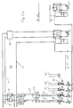
- Fig. 1 shows a first embodiment in a circuit and functional diagram of the system for monitoring and securing the transfer process between a fictitious tanker 19 and an underground one Storage container 20 with dome shaft 21. With 11 is the current one Level marked. In the storage container 20 is at the maximum permissible liquid level of the limit indicator 10 arranged. There is a voltage supply on the tanker 19 1 with the power source 2, for example a conventional 24 volt battery arranged.
- the power supply 1 of the limit transmitter 10 has a DC / DC converter 9 on a potential-free circuit 3, with at least one of the filling hose 30 and / or the gas pendulum hose 31 and / or their fittings 15 to 18 associated with them directly or via mechanically / electrodynamically excitable means 33 to 36 (see FIG.
- the coil S1 draws its negative potential from the circuit 3 of the Limit switch 10, the negative potential between the voltage source the limit value supply 1 and the switch C1 is tapped.
- the limit transmitter 10 is located between Switch C1 and the plus potential of the voltage source for supply of the limit switch 10.
- the plus potential is on the tanker of the gas pendulum hose 31 with the minus potential of Voltage source 1, 2 connected.
- the gas pendulum hose 31 is between the tap and the transport tank of the tanker vehicle 19 isolated by insulation 25.
- the selector switch C3 is used for a storage tank for petrol set to position 1 and with a storage tank for diesel fuels to position 2.
- the selector switch C3 is switched in the simplest case, manually.
- switch C2 Tears all or part of a hose during the filling process off, switch C2 is opened, then coil S1 does not flow Current, switch C1 opens, limit switch 10 and limit switch electronics 90 interrupt the filling process of the storage container 20, preferably by a known quick-closing valve in the filler neck 5 of the tanker 19.
- the switch remains C1 opened, the circuit of the limit indicator 10 remains open, the limit indicator electronics 90 do not release the filling process. Tears the filling hose 30 completely or during the filling process partially off, switch C1 is opened, the limit indicator electronics 90 immediately interrupts the filling process of the storage container 20th
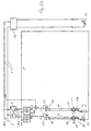
- Fig. 2 shows an essentially similar circuit and functional diagram of the system of FIG. 1 with the difference that the Connection couplings of the fittings 17, 18 for filling hose 30 and Gas suspension hose 31 additional electromechanical monitors 38, 39 are provided. It is based on an exemplary in the embodiment shown in FIG. 6 by a known per se liquid-tight coupling 15 to 18 at the connection points between filling hose 30 on the one hand and filling pipe socket 5 / filling nozzle 2 on the other hand, or a corresponding gas-tight coupling between the gas pendulum hose 31 on the one hand and the gas pendulum tube 23 / connecting piece 6 on the other.
- FIG. 6 is one purely exemplary embodiment shown with a so-called screw coupling, in which hook-shaped claws 26, 27 helical Reach under guides 28, 29 and by rotating the Seal the coupling halves together.
- a magnetic switch on the side 44 arranged, the closed when the claw 26 is properly seated is, so that the circuit 3 of the limit switch 10 - like 1 - closed.
- the coupling halves for example the magnet 45 - it can also be a magnetic ring - from the intended position raised by spring force.
- the magnets M1, M2 see FIG. 2
- the corresponding interruption switch CM1 or CM2 opened and the circuit 3 of the Limit transmitter 10 interrupted
- the switching electronics 90 the Filling process on the vehicle-side connections blocks or interrupts.
- the other switching elements correspond to the system of FIG. 1.
- Fig. 3 are the previously described electromechanical Monitors 38, 39 in series in circuit 3 of the limit switch 10 switched.
- the safety switches C1 and C2 have been omitted.
- Figure 2a shows a circuit variant of Figure 2.
- the positive The potential of two DC / DC converters 9 becomes after an insulating piece 25 to the electrically conductive filling hose 30 or to the gas pendulum hose 31 connected.
- the current flows up to one at a time electromechanical scanning 38, 39, which the reed sensors Current flow only enabled if the hose connection is correct.
- the circuit is in each case via a third line 1 'in the limit indicator connecting cable realized. If the circuit is closed, close it the reed relays d11 and d12 the limit transmitter circuit. At Open hose tear or incorrect hose connection d11 and / or d12, interrupt the limit transmitter circuit and terminate immediately the filling process.
- FIG. 2 has only changed that the mass via an additional line 1 'to Tanker 19 is performed.
- the reed relay d12 is bridged, because in this case the Monitoring of a gas pendulum hose is not necessary.
- Schematic is in Fig. 2a also shows the case that a second storage container 20 'each with a filling hose 30' or a gas pendulum hose 31 ' is arranged.
- Reed relays d21 and d22 close the limit switch circuit, if the circuit via DC / DC converter (not closer shown) and via conductive filling hose and gas pendulum hose and after approval of the electromechanical monitoring of the couplings closed is.
- Figure 2b shows a further circuit variant.
- the positive potential two DC / DC converter 9 is after an insulating piece 25 to the electrically conductive filling hose 30 or to the gas pendulum hose 31 connected.
- the current flows up to one electromechanical Sampling 38, 39, the current flow via reed sensors only releases if the hose connection is correct.
- the circuit will each via a third line 1 'in the limit indicator connection cable realized. Is the gas pendulum hose 31 when filling petrol correctly connected, reed relay d11 closes the circuit via the filling hose 30.
- the circuit closed in this way via the filling hose 30 gives the reed relay d10 Power supply of the limit switch 10 free, so that the filling process is released.
- the switch d11 When filling diesel fuel (without Gas swing) the switch d11 is bridged in the diesel dome shaft, so that the correctly connected filling hose 30 the power supply the limit switch 10 unlocks. If the hose breaks or incorrect reed connection open reed relays d10 and / or d11, interrupt the power supply to the limit switch circuit and immediately stop the filling process. Compared to the circuit variant 2a has changed that no longer in the circuit of the limit switch 10 is intervened, but in the power supply the limit switch 10.
- FIGS. 4 and 5 are another embodiment of the filling hose safety system shown, in which the monitoring of the correct Seat of the hoses and couplings in particular the demolition of one Hose when filling storage containers with the help of structure-borne noise detected and the filling process is interrupted immediately.
- the system is with alternative designs in FIGS. 4 and 5 shown.
- electro-acoustic acceleration sensors 33 and 34 are arranged, which interact with integrated circuit breakers 35, 36 and with a pre-programmed change in the frequency range of the sound waves generated, the acceleration sensors 34, 35 activate, which then open the switches 35, 36, thereby interrupt the circuit of the limit switch 10 and suddenly stop the filling process.
- the acceleration sensors 33, 34 have their own power supply 7, 8 and are otherwise connected to the limit indicator electronics 90.
- the acceleration sensors 33, 34 thus monitor the entire Resonance chamber of the filling line 5, 22, 30 or the gas suspension line 6, 23, 31 and are able to deal with any disturbance occurring therein manifests itself in a frequency-dependent damping of structure-borne noise, report spontaneously and thus interrupt the filling process.
- This is done by the transfer function of the sound conducting Complete system such as outlet nozzle, filling hose, storage tank, piping, Gas pendulum hose, connecting piece etc. depending on the excited vibrations recorded by measurement and digital in the Evaluation electronics is stored.
- the transfer function changes significantly. This is immediately done by the evaluation electronics by comparison with the stored target transfer function detected.
- the filling process is carried out with the help of the limit indicator electronics 90 controlled. This is done in the electrical supply line 3 of the limit indicator 10 an electrodynamic switching relay installed. are Filling hose 30 and gas pendulum hose 31 properly connected, the switching relay is replaced by the evaluation electronics Accelerometer switched, i.e. the contact is closed. The filling process continues until the limit transmitter 10 interrupts the current flow when in contact with fuel in the storage container 20, and so the filling process stops immediately. Now tear the filling hose 30 or gas pendulum hose 31, the structure-borne noise transfer function changes; a sensor 33 or 34 responds, interrupts the current flow by switching a switching relay 35, 36, and the limit value transmitter electronics 90 ends the instantaneous Filling process.
- a second variant of functional security using structure-borne noise is shown by way of example in FIG. 5.
- This variant is on the tanker 19, at its outlet 5 for the fuel electroacoustic, dynamic sound generator 49 permanently mounted.
- the Structure-borne noise generated in a certain frequency spectrum is over the filler pipe socket 5, the filler hose 30, the filler pipe 22 and further through the interior of the storage container 20 through the Gas pendulum tube 23 in the dome shaft 21, further through the gas pendulum hose 31, and the connecting piece 6 on the vehicle 19 to the acceleration sensor 48 headed.
- the acceleration sensor 48 is in the Able to record the incoming structure-borne noise.
- Evaluation electronics 90 which are dependent on certain frequency windows determined that the structure-borne noise actually through the filling hose 30 / gas pendulum hose 31 has reached.
- the respective transfer function is dependent on the excited one Vibrations recorded by measurement technology and digitally in the evaluation electronics filed. Is the transmission of structure-borne noise in this Chain interrupted by tearing off a hose 30, 31, so changes the transfer function is essential. This will be instantaneous through the evaluation electronics of the acceleration sensor 48 detected and converted into a control pulse. Through this the break switch 43 is opened, which then circuit 3 (Fig. 1) the limit switch 10 interrupts and so the filling process either does not release or stop immediately.
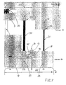
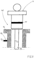
- FIG. 7 is a diagram of an electromechanical monitoring the seat shown by the dipstick.
- Such monitoring is required because practical experience shows that the operating personnel during the decanting process on the storage container 20th pull the existing dipstick 13 out of the guide tube 12 because it does so due to the reduction in the pressure difference during the transfer process displaced gas volume the filling process by up to 20 to 25% is shortened.
- To ensure this electromechanical monitoring of the dipstick seat provided, with the help of which the filling process is only released will be when the dipstick 13 is inserted into the guide tube 12 and Head 14 is properly locked.
- the guide tube 12 is working correctly Monitoring device 40 attached to the improper Seat and / or locking of the dipstick 13 the circuit 3 of Limit switch 10 interrupts and this the refilling process on Tanker 19 switches off.
- the device can preferably be attached to the guide tube 12 Have electromechanical scanning 40, with which when properly Locking the dipstick 13 by a tilting, rotating or Tilt-turn movement or the like on the head 14 of the dipstick 13 arranged magnet 41 corresponding to a representation in FIG. 8 in cooperation with one attached to the guide tube 12 Magnetic switch 42 activates this as soon as the magnet 41 is approximately in the horizontal plane of the magnet (reed) switch 42 has reached. The head 14 of the dipstick 13 is then in the guide tube 12 locked properly. The magnetic switch 42 closes one integrated in the circuit 3 of the limit indicator 10 Branch circuit 130, circuit 3, with current via the limit switch 10 flows and this releases the transfer process.
- the head 14 of the Dipstick 13 consists of electrically conductive material like brass, due to its conductivity when properly locked Head of the dipstick 13 of the secondary circuit 130 and at the same time this the circuit 3 closed and the transfer process released becomes.
- the filling process is instantaneous interrupted as soon as the dipstick 13 or the dipstick head 14 not properly in the area of the upper opening of the dipstick guide tube 12 is locked.
- FIG. 10 to 13 is an electrical circuit diagram (Fig. 10) and on the other hand are electromechanical monitoring elements and switching arrangements (Fig. 11 to 13) on hose coupling parts shown with integrated monitoring elements.
- Figure 10 shows that in line 101 via DC / DC converter 9 between the negative potential of the voltage supply 1, 2 and the positive Potential of the limit switch 10, as shown in detail in the 11a to 11d can be seen, the coupling part 52 on the tanker connector 5 and the coupling part 54 on the filling tube 22 of the Storage tanks 20 each have an interruption (reed) switch 62, 64, and the Coupling part 56 on the tanker connector 6 and the coupling part 58 an interruption (reed) switch on the gas pendulum tube 23 of the storage tank 20 66, 68 is assigned, as well as the corresponding Couplings 72, 74 of the filling hose 30 and the couplings 76, 78 of the gas pendulum hose 31 each have a scanning permanent magnet 82, 84 and 86, 88, each firmly in the connector of the hose is integrated, is assigned, wherein the reed switches 62 to 68 according to the circuit diagram of FIG. 10 connected in series with one another via secondary circuit 131, 132 and un the
- both coupling parts have to be exchanged, provided the hose connection on the tanker truck is monitored should. If only the hose connection in the dome shaft is to be monitored, it is not necessary to swap both coupling parts.
- On the The hose end belonging to the manhole is located as outlined Coupling part with the hook-shaped claws 74, 78 already on Hose end.
- the reed switches 62, 64, 66, 68 are in the circuit 3 of the Limit transmitter 10 integrated, each via secondary circuits 131, 132 and are without the presence of a magnetic Field opened.
- a permanent magnet 62, 64, 66, 68 due to a rotary movement of the corresponding fittings the reed switches are switched and thus the circuit 3 of the limit switch 10 closed.
- Monitoring the individual connections between hose 30, 31 and tank truck 19 or storage container 20 is connected in series and in the circuit 3 of the limit indicator introduced so that only after connection of all couplings 15, 16, 17, 18 this circuit 3 is closed.
- the supervision individual connections can be made either by reed switches and several Permanent magnets, through several reed switches and a permanent magnet or by several reed switches and several permanent magnets respectively. If multiple reed switches to monitor the If a connection is available, they must be connected in parallel be.
- the closing of the clutches and thus the approach between permanent magnets and reed switches by placing and lateral rotation of the coupling parts 73, 74, 76, 78 and locking the lever 89 in the folded position. This is can be seen in detail from FIGS. 12a, 12b and 13.
- FIG. 12a shows the rotatable coupling element on the filling hose 30 72 with the foldable hand lever 89 and the claw-shaped Holding elements 26 and 27. These engage in helical guides 28, 29 of the coupling piece 52 fastened to the filler pipe socket and are symbolized by a rotational movement, symbolized by an elliptical Arrow, locked and sealed. 12a and 12b the clutch 15 is still open. Then there is the permanent magnet 82 with its magnetic field outside the field area of the reed switch 62, which is then still open and the entire circuit the limit transmitter 10 keeps interrupted.
- Exemplary embodiments are the functional principle according to the invention Describe the processes that can be assigned to the system as follows: an existing level monitoring system with limit switch for the fill level in the storage container connected safety device, Which existing system elements are included is at a malfunction of the system elements by changing the electrical Resistance simulated an upper tank level, or by Interruption of the circuit of a limit switch that is not connected is displayed, after which the limit indicator electronics complete the transfer process interrupts.
- This system is used in particular for monitoring and securing a transfer process between a tanker vehicle 19 for fuels and an underground storage container 20, which in a dome shaft 21 with a filling pipe 22 and a gas pendulum pipe 23 has, during the transfer process through a filling hose 30 and a gas pendulum hose 31 on the one hand to a filling device 5, 6 with connection fittings 15, 16 of the tanker 19 and on the other hand on the filling pipe 22 and gas pendulum pipe 23 of the storage container 20 can be connected and a voltage supply to the tanker 19 1, 2 a potential-free circuit via a DC / DC converter 9 3 forming a limit switch which switches the filling device 5, 6 10 with electronics 90, which when a predetermined filling level 11 in the storage container 20 the filling process prevents or interrupts, the circuit 3 of the limit switch 10 or its electronics 90 are connected so that they Filling process with closed circuit depending on resistance release and / or do not release if the circuit is interrupted or interrupt and the method is characterized in that the circuit of the
- the system is used according to the claims 1 to 9 for monitoring and securing a transfer process between a tanker 19 and an underground storage container 20 and in particular for the immediate interruption of the transfer process Breakage and / or incorrect connection of filling hose 30 or Filling hose 30 and gas pendulum hose 31.
- Another use of the monitoring system according to the invention relates to the filling of underground storage containers 20 with central filling shaft.
- the special The problem is that the gas pendulum tubes 23 are not assigned to the respective filler tubes 22 or limit switches 10 more possible is.
- the filling hose safety device is based on the same principle as for the single filling dome.
- the circuit is constructed so that the Circuit created via the gas pendulum hose via the minus potential of the limit switch circuit or via a third Line 1 'in the limit switch connection cable closes.
- the electrical Connections of this gas pendulum hose 31 to all other limit indicators 10 is by reed relay, which by the existing Circuit are switched, interrupted. For example, become the second Filling tube 30 'with associated limit transmitter 10' and the second Gas pendulum hose 31 'connected, closes as before described the limit transmitter circuit and in turn all other electrical connections to the remaining limit switches interrupted.
- FIGS. 1 to 13 are to be understood only as an example.
- the scanning elements 38, 39 (Fig. 2, Fig. 3) regarding their execution, for example. with regard to the arrangement and design of the switching elements 44, 45 left to the professional discretion of the designer.
- the design and arrangement of acceleration sensors 48 and sound generators 49 The functionality of the System is due to a redundant design of the switching elements, For example, the limit switch 10 is significantly increased.
- the invention optimally fulfills the task set out above, in particular because it is ensured that the filling process for the storage container is only possible if the limit indicator, filling hose and gas pendulum hose are connected in a dome shaft.
Landscapes
- Engineering & Computer Science (AREA)
- Mechanical Engineering (AREA)
- Filling Or Discharging Of Gas Storage Vessels (AREA)
- Testing Electric Properties And Detecting Electric Faults (AREA)
Description
- Figur 1
- ein Schalt- und Funktionsschema des Systems mit zur Überwachung des Umfüllvorganges zwischen einem Tankfahrzeug und einem unterirdischen Lagerbehälter mittels elektrischem Strom;
- Figur 2
- ein Schalt- und Funktionsschema des Systems mit Sicherung durch elektrischen Strom und mechanische Abtastung;
- Figur 2a
- ein Schalt- und Funktionsschema mit zwei DC/DC Wandlern und Schaltung des Grenzwertgeberstromkreises,
- Figur 2b
- ein Schalt- und Funktionsschema mit zwei DC/DC Wandlern und Schaltung der Stromversorgung des Grenzwertgebers,
- Figur 3
- ein Schalt- und Funktionsschema eines Sicherungssystems für Schlauchanschlüsse mit mechanischer Abtastung;
- Figur 4
- ein Schalt- und Funktionsschema einer Abfüllsicherung mit mechanischer und elektrodynamischer Anregung und Beschleunigungssensoren;
- Figur 5
- eine andere Ausführung eines Sicherungssystems mit elektrodynamischer Anregung und Beschleunigungssensoren;
- Figur 6
- in Ansicht und teilweise im Schnitt eine elektromechanische Abtastung an einem Schlauchanschluß;
- Figur 7
- ein Schema einer elektromechanischen Überwachung des Peilstabsitzes;
- Figur 8
- Mittel zur Anschlußüberwachung des Peilstabsitzes durch elektromagnetische Abtastung am Führungsrohr;
- Figur 9
- Mittel zur elektrischen Anschlußüberwachung des Peilstabsitzes durch eine Kontaktbrücke;
- Figur 10
- ein Schema einer Abfüllschlauchsicherung mit elektromechanischer Abtastung der Anschlußkupplungen;
- Figur 11a-11d
- Anordnung von Überwachungsmagneten und Reed-Schaltern an Schlauchkupplungen;
- Figur 12a, 12b
- Schlauchkupplungsteile mit integrierten Überwachungselementen, im geöffneten Zustand;
- Figur 13
- die Schlauchkupplungsteile gem. Fig. 12a, 12b im ordnungsgemäß gekuppelten Zustand.
- eine Leitung 100 zwischen dem Plus-Potential der Spannungsversorgung 1, 2 des Tankfahrzeugs 19 über einen DC/DC-Wandler 50 und dem Füllschlauch 30 oder Füllschlauchstutzen 5;
- eine Leitung 101 zwischen dem Minus-Potential des DC/DC-Wandlers 9, 50 und dem Minus-Potential des Grenzwertgebers 10;
- eine am Plus-Potential des Füllrohres 22 im Domschacht 21 angeschlossene Leitung 102 mit einer Verzweigung in zwei Leitungsäste 103, 104, von diesen abzweigend
- einen Ast 103 mit einer Relaisspule S2 mit Schalter C2 und Anschluß an einen zwischen den Isolationen 24, 25 angeordneten isolierten Bereich des Gaspendelschlauches 31 oder Gaspendelrohres 23;
- einen Ast 104 mit Wahlschalter C3 und anschließender Leitung 105 für das Plus-Potential mit Verbindung entweder direkt oder über Schalter C2 an die Spule S1 mit Schalter C1;
- eine Verbindung der Spule S1 mit der Leitung 106 an das Plus-Potential des Stromkreises vom Grenzwertgeber 10, wobei
- die Leitung über DC/DC-Wandler 9 zwischen der Spannungsversorgung 1, 2 und dem Schalter C1 angeschlossen ist;
- der Grenzwertgeber 10 zwischen Schalter C1 und über DC/DC-Wandler 9 dem Plus-Potential der Spannungsversorgung 1 angeschlossen ist;
- und das Plus-Potential des isolierten Gaspendelschlauches 31 über DC/DC-Wandler 9 mit dem Minus-Potential der Spannungsversorgung 1, 2 über eine Leitung 107 verbunden ist.
Claims (22)
- System zur Überwachung und Sicherung des Umfüllvorganges zwischen einem Tankfahrzeug (19) und einem insbesondere unterirdischen Lagerbehälter (20) oder einem anderen Tankfahrzeug oder zwischen Lagerbehältern, wobei zumindest ein Schlauch (30, 31) mittels einer Umfüllvorrichtung (5, 6) mit Anschlußarmaturen (15, 16) bspw. am Tankfahrzeug (19) an mindestens ein Umfüllrohr (22, 23) bspw. des Lagerbehälters (20) anschließbar ist und wobei das Überwachungssystem mit einer Spannungsversorgung (1, 2) einen Stromkreis (3) bildend einen die Umfüllvorrichtung (5, 6) schaltenden Füllstands-Grenzwertgeber (10) am Lagerbehälter (20) aufweist,
gekennzeichnet durch
wenigstens eine dem vorhandenen Füllstands-Überwachungssystem (1, 2, 3, 10) aufgeschaltete fehlersicher arbeitende Sicherheitsvorrichtung, die bei einem fehlerhaften Umfüllvorgang den Stromkreis (3) des Grenzwertgebers (10) unterbricht und dieser die Umfüllvorrichtung am Tankfahrzeug (19) abschaltet. - System zur Überwachung und Sicherung des Umfüllvorgangs zwischen einem Tankfahrzeug (19) und einem insbesondere unterirdischen Lagerbehälter (20) oder einem anderen Tankfahrzeug oder zwischen Lagerbehältern, das insbesondere in einem Domschacht (21) mindestens ein Füllrohr (22) und mindestens ein Gaspendelrohr (23) aufweist und diese durch einen Füllschlauch (30) und einen Gaspendelschlauch (31) einerseits an eine Abfüllvorrichtung (5, 6) mit Anschlußarmaturen (15, 16) bspw. des Tankfahrzeuges (19) und andererseits am Füllrohr (22) und Gaspendelrohr (23) bspw. des Lagerbehälters (20) anschließbar sind, wobei das System mit mindestens einer Spannungsversorgung (1, 2) des Tankfahrzeuges (19) über mindestens einen DC/DC-Wandler (9) einen potentialfreien Stromkreis (3) bildend einen die Abfüllvorrichtung (5, 6) schaltenden Grenzwertgeber (10) mit einer Elektronik (90) aufweist, die bei Erreichen eines vorgegebenen Füllstands (11) im Lagerbehälter (20) den Füllvorgang verhindert, unterbricht oder beendet, wobei der Stromkreis des Grenzwertgebers (10) oder dessen Elektronik (90) Schaltmittel aufweist, die so geschaltet und ausgebildet sind, daß sie den Befüllvorgang bei geschlossenem Stromkreis freigeben und bei unterbrochenem Stromkreis nicht freigeben oder unterbrechen,
dadurch gekennzeichnet,
daß der Stromkreis (3) des Grenzwertgebers (10) und/oder dessen Schalt-Elektronik (90) mindestens eine dem Füllschlauch (30) und/oder Gaspendelschlauch (31) und/oder deren Armaturen (15 bis 18) zugeordnete und mit diesen unmittelbar oder über mechanisch/elektrodynamisch anregbare Mittel (33 bis 36) zusammenwirkende zusätzliche Schaltkreisanordnung aufweist, welche den Stromkreis (3) des Grenzwertgebers (10) geschlossen hält, solange der Füllschlauch (30) oder Füllschlauch (30) und Gaspendelschlauch (31) korrekt mit ihren Armaturen (15 bis 18) an den lagerbehälterseitigen und/oder fahrzeugseitigen Anschlüssen (5, 6; 22, 23) angeschlossen oder nicht unterbrochen sind, und den Stromkreis (3) unterbricht, sobald Armaturen (15 bis 18) oder Schläuche (30, 31) nicht korrekt angeschlossen sind oder Schläuche (30, 31) ganz oder teilweise abgerissen sind. - System nach Anspruch 2,
dadurch gekennzeichnet,
daß die zusätzliche Schaltkreisanordnung folgende Merkmale umfaßt:eine Leitung (100) zwischen dem Plus-Potential der Spannungsversorgung (1, 2) des Tankfahrzeugs (19) über einen DC/DC-Wandler (50) und dem Füllschlauch (30) oder Füllrohrstutzen (5);eine Leitung (101) zwischen dem Minus-Potential der DC/DC-Wandler (9, 50) und dem Minus-Potential des Grenzwertgebers (10);eine am Plus-Potential des Füllrohres (22) angeschlossene Leitung (102) mit einer Verzweigung in zwei Leitungsäste (103, 104), von diesen abzweigendeinen Ast (103) mit einer Relaisspule (S2) mit Schalter (C2) und Anschluß an einen zwischen den Isolationen (24, 25) angeordneten isolierten Bereich des Gaspendelschlauches (31) oder Gaspendelrohres (23);einen Ast (104) mit Wahlschalter (C3) und anschließender Leitung (105) für das Plus-Potential mit Verbindung entweder direkt oder über Schalter (C2) an die Spule (S1) mit Schalter (C1);eine Verbindung der Spule (S1) mit der Leitung (106) an das Plus-Potential des Stromkreises vom Grenzwertgeber (10), wobei die Leitung über DC/DC-Wandler (9) zwischen der Spannungsversorgung (1, 2) und dem Schalter (C1) angeschlossen ist undder Grenzwertgeber (10) zwischen Schalter (C1) und über DC/DC-Wandler (9) dem Plus-Potential der Spannungsversorgung (1) angeschlossen ist unddas Plus-Potential des isolierten Gaspendelschlauches (31) über DC/DC-Wandler (9) mit dem Minus-Potential der Spannungsversorgung (1, 2) über eine Leitung (107) verbunden ist. - System nach Anspruch 2,
dadurch gekennzeichnet,
daß der Wahlschalter (C3) wenigstens zwei Stellungen (Pos. 1/Pos. 2) zur Wahl unterschiedlicher Füllmedien, bspw. Ottokraftstoff oder Dieselkraftstoff aufweist (Fig. 1). - System nach Anspruch 1 bis 4,
dadurch gekennzeichnet,
daß in der Leitung (101) über DC/DC-Wandler (9) zwischen dem negativen Potential der Spannungsversorgung (1,2) und dem positiven Potential des Grenzwertgebers (10) einerseits ein der Kupplung (17) zwischen Füllrohr (22) und Füllschlauch (30) zugeordneter Unterbrechungsschalter (CM1) und andererseits, mit diesem in Reihe geschaltet, ein der Kupplung (18) zwischen Gaspendelrohr (23) und Gaspendelschlauch (31) zugeordneter Unterbrechungsschalter (CM2) mit jeweils einer mechanisch/elektrischen Abtastung (38, 39) der Kupplungen (17, 18) zusammenwirkend angeordnet ist, wobei die Abtastungen (38, 39) den korrekten Sitz jeder Kupplung (17, 18) überwachen und bei fehlerhaftem Sitz über Magnete oder Spulen (M1, M2) die entsprechenden Unterbrechungsschalter (CM1) oder (CM2) öffnen und den Stromkreis (3) des Grenzwertgebers (10) unterbrechen, dessen Elektronik (90) den Füllvorgang sperrt oder unterbricht. - System nach Anspruch 5,
dadurch gekennzeichnet,
daß die elektro/mechanische Abtastung (38, 39) ein mit der Kupplung (17, 18) mechanisch zusammenwirkender Magnetschalter (44) ist, der bei nicht korrektem Sitz einer Kupplung (17, 18) bzw. des Magnetringes (45) oder des Magnetschalters (44) den entsprechenden Unterbrechungsschalter (CM1, CM2) öffnet und den Stromkreis (3) des Grenzwertgebers (10) unterbricht. - System nach mindestens einem
der vorhergehenden Ansprüche 1 bis 6,
dadurch gekennzeichnet,
daß das Plus-Pontential zweier DC/DC-Wandler (9) jeweils nach einem Isolierstück (25) an den elektrisch leitfähigen Füllschlauch (30) bzw. Gaspendelschlauch (31) angeschlossen ist, die ihrerseits jeweils nach einem Isolierstück (24) und mechanisch/elektrischer Abtastung (38, 39) der Kupplungen (17, 18) sowie über Reedrelais (d11, d12) auf die gemeinsame Masseleitung oder auf eine dritte Leitung (1') im Grenzwertgeberanschlußkabel geschaltet sind und die dritte Leitung (1') mit dem Minus-Potential der DC/DC-Wandler (9) verbunden ist, wobei die Reedrelais bei nicht ordnungsgemäßem Anschluß der Schläuche den Grenzwertgeberstromkreis unterbrechen und so den Füllvorgang beenden bzw. nicht freigeben. - System nach mindestens einem
der vorhergehenden Ansprüche 1 bis 6,
dadurch gekennzeichnet,
daß das Plus-Potential zweier DC/DC-Wandler (9) jeweils nach einem Isolierstück (25) an den elektrisch leitfähigen Füllschlauch (30) bzw. den Gaspendelschlauch (31) angeschlossen ist, die ihrerseits jeweils nach einem Isolierstück (24) und mechanisch/elektrischer-Abtastung (38, 39) der Kupplungen (17, 18) sowie über ein gemeinsames Reedrelais (d11) auf eine dritte Leitung (1') im Grenzwertgeberanschlußkabel geschaltet ist und die dritte Leitung (1') mit dem Minus-Potential der DC/DC-Wandler (9) verbunden ist und daß in dem Stromkreis (9, 30, 1') über den Füllschlauch (30), vorzugsweise zwischen DC/DC-Wandler (9) und Füllschlauch (30) ein Reedrelais (d10) angeordnet ist, das in die Stromversorgung (2) des Grenzwertgebers (10) geschaltet ist (Schalter d10), wobei das Reedrelais (d10) die Stromversorgung (2) des Grenzwertgebers (10) bei korrekt angeschlossenem Füllschlauch (30) freigibt oder anderenfalls unterbricht. - System nach einem oder mehreren der Ansprüche 1 bis 8,
dadurch gekennzeichnet,
daß in der Leitung (101) über DC/DC-Wandler (9) zwischen dem negativen Potential der Spannungsversorgung (1, 2) und dem positiven Potential des Grenzwertgebers (10) dem Kupplungsteil (52) am Tankwagen-Anschlußstutzen (5) und dem Kupplungsteil (54) am Füllrohr (22) des Lagertanks (20) je mindestens ein Unterbrechungs(Reed)-Schalter (62, 64), und dem Kupplungsteil (56) am Tankwagen-Anschlußstutzen (6) sowie dem Kupplungsteil (58) am Gaspendelrohr (23) des Lagertanks (20) je mindestens ein Unterbrechungs(Reed)-Schalter (66, 68) zugeordnet sind, sowie den korrespondierenden Anschlußkupplungen (72, 74) des Füllschlauches (30) und den Anschlußkupplungen (76, 78) des Gaspendelschlauches (31) je ein Abtast-Permanentmagnet (82, 84 bzw. 86, 88) zugeordnet ist, daß die Reed-Schalter (62 bis 68) über Nebenstromkreise (131, 132) untereinander gegebenenfalls parallel geschaltet und in den Stromkreis (3) des Grenzwertgebers (10) in Reihe integriert sind, und dieser erst nach ordnungsgemäßer Verbindung aller Kupplungsteile (52 bis 58) mit Anschlußkupplungen (72 bis 78) geschlossen und der Umfüllvorgang freigegeben wird. - System nach Anspruch 1 oder 2,
dadurch gekennzeichnet,
daß der Stromkreis (3) des Grenzwertgebers (10) und dessen Elektronik (90) eine zusätzliche Schaltkreisanordnung mit sowohl dem Füllrohr (22) als auch dem Gaspendelrohr (23) im Domschacht (21) zugeordneten, mit integrierten Unterbrechungsschaltern (35, 36) zusammenwirkenden elektro-akustischen Beschleunigungssensoren (33, 34) aufweist, und daß am Füllrohrstutzen (5) des Tankfahrzeuges (19) und/oder fallweise am fahrzeugseitigen Anschlußstutzen (6) des Gaspendelschlauches (31) jeweils ein elektrodynamischer Schallerzeuger (49) angeordnet ist. - System nach Anspruch 10,
dadurch gekennzeichnet,
daß die Beschleunigungssensoren (33, 34) den Stromkreis (3) des Grenzwertgebers (10) unterbrechen. - System nach Anspruch 1 oder 2,
dadurch gekennzeichnet,
daß ein Schallerzeuger (49) am fahrzeugseitigen Füllstutzen (5) und ein elektro-akustischer Beschleunigungssensor (48) am Anschlußstutzen (6) für den Gaspendelschlauch (31) angeordnet ist und dieser einen in den Stromkreis (3) des Grenzwertgebers (10) integrierten und mit diesem zusammenwirkbar ausgebildeten Unterbrecherschalter (43) aufweist. - System zur Überwachung und Sicherung des Umfüllvorganges zwischen einem Tankfahrzeug (19) und einem insbesondere unterirdischen Lagerbehälter (20) nach einem oder mehreren der Ansprüche 1 bis 12, wobei der Lagerbehälter (20) insbesondere im Domschacht (21) außer einem Füllrohr (22) und einem Gaspendelrohr (23) ein Führungsrohr (12) für einen Peilstab (13) aufweist,
dadurch gekennzeichnet,
daß am Führungsrohr (12) eine fehlerfrei arbeitende Überwachungsvorrichtung (40) angebracht ist, die bei ordnungsgemäßem Sitz und/oder Verriegelung des Peilstabes (13) den Stromkreis (3) des Grenzwertgebers (10) geschlossen hält und den Umfüllvorgang freigibt und bei gezogenem oder nicht ordnungsgemäßem Sitz und/oder Verriegelung vom Peilstab (13) den Stromkreis (3) des Grenzwertgebers (10) unterbricht und dieser den Umfüllvorgang am Tankfahrzeug (19) abschaltet. - System nach Anspruch 13,
gekennzeichnet durch
eine am Führungsrohr (12) angebrachte elektromechanische Abtastung (40), mit welcher bei ordnungsgemäßer Verriegelung des Peilstabes (13) durch eine Kipp-, Dreh- oder Kipp-Dreh-Bewegung oder dergleichen ein am Kopf (14) des Peilstabes (13) angeordneter Magnet (41) im Zusammenwirken mit einem am Führungsrohr (12) angebrachten Magnetschalter (42) diesen aktiviert und dabei durch einen in den Stromkreis (3) des Grenzwertgebers (10) integrierten Nebenstromkreis (130) den Stromkreis (3) schließt, wodurch der Umfüllvorgang freigegeben wird. - System nach Anspruch 14,
dadurch gekennzeichnet,
daß das Führungsrohr (12) aus nichtleitendem Material wie Kunststoff ausgeführt und mit eingearbeiteten Kontakten (131, 132) ausgebildet ist, die den Nebenstromkreis (130) und über diesen zugleich den Stromkreis (3) des Grenzwertgebers (10) unterbrechen, und daß der Kopf (14) des Peilstabes (13) aus elektrisch leitfähigem Material wie Messing besteht, durch dessen Leitfähigkeit bei korrekt verriegeltem Kopf des Peilstabes (13) der Nebenstromkreis (130) und zugleich durch diesen der Stromkreis (3) geschlossen und der Umfüllvorgang freigegeben wird. - System nach Anspruch 13,
dadurch gekennzeichnet,
daß die Überwachungsvorrichtung (40) zur Ein- oder Ausschaltung des Nebenstromkreises (130) Mittel wie eine Lichtschranke oder einen Körperschallerzeuger im Zusammenwirken mit einer in der Elektronik (90) des Grenzwertgebers (10) abgespeicherten SOLL-Übertragungsfunktion aufweist. - System nach einem oder mehreren der Ansprüche 13 bis 16,
dadurch gekennzeichnet,
daß die Nebenstromkreise (130 bis 132) mit dem Stromkreis (3) des Grenzwertgebers (10) in Reihe geschaltet sind. - Verfahren zur Überwachung und Sicherung eines Umfüllvorgangs zwischen einem Tankfahrzeug (19) und einem insbesondere unterirdischen Lagertank (20)oder einem anderen Tankfahrzeug oder zwischen Lagerbehältern, wobei insbesondere in einem Domschacht (21) mindestens ein Füllrohr (22) und mindestens ein Gaspendelrohr (23) vorhanden sind und diese durch einen Füllschlauch (30) und einen Gaspendelschlauch (31) einerseits an eine Abfüllvorrichtung (5, 6) mit Anschlußarmaturen (15, 16) bspw. des Tankfahrzeuges (19) und andererseits an Füllrohr (22) und Gaspendelrohr (23) bspw. des Lagertanks (20) anschließbar sind und mindestens eine Spannungsversorgung (1, 2) des Tankfahrzeuges (19) einen potentialfreien Stromkreis (3) bildend einen die Abfüllvorrichtung (5, 6) schaltenden Grenzwertgeber (10) mit einer Elektronik (90) aufweist, die bei Erreichen eines vorgegebenen Füllstands (11) im Lagerbehälter (20) den Füllvorgang verhindert oder unterbricht, wobei der Stromkreis (3) des Grenzwertgebers (10) oder dessen Elektronik (90) so geschaltet sind, daß sie den Befüllvorgang bei geschlossenem Stromkreis widerstandsabhängig freigeben und/oder bei unterbrochenem Stromkreis nicht freigeben oder unterbrechen,
dadurch gekennzeichnet,
daß der Stromkreis (3) des Grenzwertgebers (10) und/oder dessen Elektronik (9) mit mindestens einer dem Füllschlauch (30) und/oder Gaspendelschlauch (31) und/oder deren Armaturen (15 bis 18) und/oder dem Peilstab (13) zugeordneten und mit diesen unmittelbar oder mittelbar mechanisch/elektrodynamisch zusammenwirkenden zusätzlichen Schaltkreisanordnung in Reihe geschaltet wird, welche den Stromkreis des Grenzwertgebers geschlossen hält, solange der Peilstab (13) odnungsgemäß sitzt und/oder verriegelt ist und/oder solange der Füllschlauch (30) und/oder Gaspendelschlauch (31) korrekt mit ihren Armaturen (15 bis 18) an den lagerbehälterseitigen und/oder fahrzeugseitigen Anschlüssen (5, 6; 22, 23) angeschlossen oder nicht unterbrochen sind, und den Stromkreis unterbricht, sobald Armaturen (40, 15 bis 18) oder Schläuche (30, 31) nicht korrekt angeschlossen sind oder Schläuche (30, 31) ganz oder teilweise abgerissen sind oder der Peilstab (13) nicht korrekt sitzt oder nicht verriegelt ist. - Verwendung des Systems nach den Ansprüchen 1 bis 17,
zur Überwachung und Sicherung eines Umfüllvorgangs, insbesondere von Kraftstoffen zwischen einem Tankfahrzeug (19) und einem unterirdischen Lagerbehälter (20) und insbesondere zur sofortigen Unterbrechung des Umfüllvorganges bei Bruch und/oder nicht korrektem Anschluß von Füllschlauch (30) oder Füllschlauch (30) und Gaspendelschlauch (31) oder nicht korrektem Sitz oder Verriegelung des Peilstabes (13). - Verwendung des Systems nach mindestens einem der Ansprüche 1 bis 17 zur Überwachung und Sicherung eines Umfüllvorgangs, insbesondere von Kraftstoffen zwischen einem Tankfahrzeug (19) und einem Lagertank (20) bei mehreren, insbesondere unterirdischen Lagerbehältern (20, 20' ...), wobei deren sämtliche Füllrohre (22, 22' ...) mit zugehörigem Grenzwertgeber (10, 10' ...) und mindestens ein, in der Regel zwei Gaspendelrohre (23, 23') in einem gemeinsamen Fülldom (21) untergebracht sind und wobei die elektrischen Verbindungen eines korrekt angeschlossenen Gaspendelschlauches (31) zu allen anderen Grenzwertgebern (10) durch Reedrelais, die durch den bestehenden Stromkreis geschaltet werden, unterbrochen werden, wenn mindestens ein Füllrohr aus der Mehrzahl der Füllrohre (22, 22' ..) mit zugehörigem Grenzwertgeber (10, 10'...) und mindestens ein Gaspendelrohr (23, 23') korrekt an ihrem Füllschlauch (30) bzw. Gaspendelschlauch (31) angeschlossen sind und der Grenzwertgeberstromkreis geschlossen ist.
- Schlauchverbindung in einem System zur Überwachung und Sicherung des Umfüllvorganges zwischen einem Tankfahrzeug (19) und einem insbesondere unterirdischen Lagerbehälter (20) oder einem anderen Tankfahrzeug oder zwischen Lagerbehältern, wobei zumindest ein Schlauch (30, 31) mittels einer Umfüllvorrichtung (5, 6) mit Anschlußarmaturen (15, 16) bspw. am Tankfahrzeug (19) an mindestens ein Umfüllrohr (22, 23) bspw. des Lagerbehälters (20) anschließbar ist und wobei das Überwachungssystem mit einer Spannungsversorgung (1, 2) einen Stromkreis (3) bildend einen die Umfüllvorrichtung (5, 6) schaltenden Füllstands-Grenzwertgeber (10) am Lagerbehälter (20) aufweist,
dadurch gekennzeichnet,
daß in einer Leitung (101, 30, 31) über mindestens einen DC/DC-Wandler (9) zwischen dem negativen Potential der Spannungsversorgung (1, 2) und dem positiven Potential des Grenzwertgebers (10) dem Kupplungsteil (52) bspw. am Tankwagen-Anschlußstutzen (5) und dem Kupplungsteil (54) bspw. am Füllrohr (22) des Lagertanks (20) je mindestens ein Unterbrechungs(Reed)-Schalter (62, 64), und dem Kupplungsteil (56) am Tankwagen-Anschlußstutzen (6) sowie dem Kupplungsteil (58) am Gaspendelrohr (23) des Lagertanks (20) je mindestens ein Unterbrechungs(Reed)-Schalter (66, 68) zugeordnet sind, sowie den korrespondierenden Anschlußkupplungen (72, 74) des Füllschlauches (30) und den Anschlußkupplungen (76, 78) des Gaspendelschlauches (31) je ein Abtast-Permanentmagnet (82, 84 bzw. 86, 88) zugeordnet ist, daß die Reed-Schalter (62 bis 68) über Nebenstromkreise (131, 132) untereinander gegebenenfalls parallel geschaltet und in den Stromkreis (3) des Grenzwertgebers (10) in Reihe integriert sind, und dieser erst nach ordnungsgemäßer Verbindung aller Kupplungsteile (52 bis 58) mit Anschlußkupplungen (72 bis 78) geschlossen und der Umfüllvorgang freigegeben wird oder den Stromfluß über die Verbindungsleitungen (30, 31) erst nach ordnungsgemäßer Verbindung aller Kupplungsteile (52 bis 58) mit Anschlußkupplungen (72 bis 78) freigibt, wobei dann die Reedrelais (d11 und d12) den Grenzwertgeberstromkreis (3) schließen, und so den Befüllvorgang freigegeben, alternativ das Reedrelais (d10) die Stromversorgung des Grenzwertgebers freigibt oder unterbricht. - Schlauchverbindung in einem beliebig gestalteten System zur Überwachung und Sicherung des Umfüllvorganges zwischen einem Tankfahrzeug (19) und einem insbesondere unterirdischen Lagerbehälter (20) oder einem anderen Tankfahrzeug oder zwischen Lagerbehältern, wobei zumindest ein Schlauch (30, 31) mittels einer Umfüllvorrichtung (5, 6) mit Anschlußarmaturen (15, 16) bspw. am Tankfahrzeug (19) und an mindestens ein Umfüllrohr (22, 23) bspw. des Lagerbehälters (20) anschließbar ist, wobei die Anschlußarmaturen (15, 16) aus mindestens zwei bspw. dem Tankfahrzeug (19) und dem Umfüllrohr (22, 23) zugeordneten Kupplungsteilen (52, 54, 56, 58) und dem Schlauch (30, 31) zugeordneten Anschlußkupplungen (72, 74, 76, 78) bestehen,
dadurch gekennzeichnet,
daß dem Kupplungsteil (52) am Tankfahrzeug-Anschlußstutzen (5) und/oder dem Kupplungsteil (54) am Füllrohr (22) des Lagerbehälters (20) je mindestens ein Unterbrechungs(Reed)-Schalter (62, 64) und/oder dem Kupplungsteil (56) am Tankfahrzeuganschlußstutzen (6) und/oder dem Kupplungsteil (58) am Gaspendelrohr (23) des Lagerbehälters (20) je mindestens ein Unterbrechungs(Reed)-Schalter (66, 68) zugeordnet ist, sowie den korrespondierenden Anschlußkupplungen (72, 74) des Füllschlauches (30) und/oder den Anschlußkupplungen (76, 78) des Gaspendelschlauches (31) je ein Abtast-Permanentmagnet (82, 84) bzw. (86, 88) zugeordnet ist, der fest in der jeweiligen Anschlußkupplung des zugehörigen Schlauchs (30, 31) integriert ist.
Priority Applications (1)
| Application Number | Priority Date | Filing Date | Title |
|---|---|---|---|
| DE29610357U DE29610357U1 (de) | 1995-03-09 | 1996-03-08 | System zur Überwachung und Sicherung des Umfüllvorganges zwischen einem Tankfahrzeug und einem unterirdischen Lagerbehälter |
Applications Claiming Priority (4)
| Application Number | Priority Date | Filing Date | Title |
|---|---|---|---|
| DE19508441 | 1995-03-09 | ||
| DE19508441 | 1995-03-09 | ||
| DE19525188 | 1995-07-11 | ||
| DE19525188A DE19525188A1 (de) | 1995-03-09 | 1995-07-11 | System und Verfahren zur Überwachung und Sicherung des Umfüllvorganges zwischen einem Tankfahrzeug und einem unterirdischen Lagerbehälter |
Publications (2)
| Publication Number | Publication Date |
|---|---|
| EP0731056A1 EP0731056A1 (de) | 1996-09-11 |
| EP0731056B1 true EP0731056B1 (de) | 1998-09-02 |
Family
ID=26013198
Family Applications (1)
| Application Number | Title | Priority Date | Filing Date |
|---|---|---|---|
| EP96103614A Expired - Lifetime EP0731056B1 (de) | 1995-03-09 | 1996-03-08 | System und Verfahren zur Überwachung und Sicherung des Umfüllvorganges zwischen einem Tankfahrzeug und einem unterirdischen Lagerbehälter |
Country Status (2)
| Country | Link |
|---|---|
| EP (1) | EP0731056B1 (de) |
| AT (1) | ATE170498T1 (de) |
Families Citing this family (3)
| Publication number | Priority date | Publication date | Assignee | Title |
|---|---|---|---|---|
| GB9621945D0 (en) * | 1996-10-22 | 1996-12-18 | Drum Engineering The Company L | Control apparatus |
| FR2775274B1 (fr) * | 1998-02-20 | 2000-05-26 | Daniel Degail | Ensemble portable pour la commande a distance du remplissage de cuves ou analogues |
| CN101332970B (zh) * | 2007-06-28 | 2012-09-12 | 湖北三六一一机械厂 | 一种铁路槽车收发油装备 |
Family Cites Families (4)
| Publication number | Priority date | Publication date | Assignee | Title |
|---|---|---|---|---|
| DE3308847C2 (de) * | 1983-03-12 | 1985-10-24 | Timm-Elektronik GmbH, 2000 Hamburg | Anordnung zur Erkennung fehlerhafter Grenzwertgeber |
| DE3642406A1 (de) * | 1986-12-11 | 1988-06-23 | Kett Reinhold Dipl Ing Fh | Elektronische ueberwachungs- und steuereinrichtung fuer abfuellsicherungen |
| DE8900653U1 (de) * | 1989-01-19 | 1989-03-30 | Fafnir GmbH, 22765 Hamburg | Abfüllsicherung |
| DE4221492A1 (de) * | 1991-07-16 | 1993-01-21 | Fafnir Gmbh | Schlauchsicherung |
-
1996
- 1996-03-08 AT AT96103614T patent/ATE170498T1/de not_active IP Right Cessation
- 1996-03-08 EP EP96103614A patent/EP0731056B1/de not_active Expired - Lifetime
Also Published As
| Publication number | Publication date |
|---|---|
| ATE170498T1 (de) | 1998-09-15 |
| EP0731056A1 (de) | 1996-09-11 |
Similar Documents
| Publication | Publication Date | Title |
|---|---|---|
| DE102007035977B4 (de) | Elektronischer Durchflusssensor | |
| EP0366215B1 (de) | Befülleinrichtung | |
| DE102011115630B4 (de) | Werkzeug zur diagnose eines grossen lecks für ein abgedichtetes kraftstoffsystem in einem fahrzeug | |
| DE102014019419A1 (de) | Verfahren und Diagnoseeinrichtung zur Überprüfung von Hochdrucktankventilen, Hochdrucktanksystem und Kraftfahrzeug mit einem Hochdrucktanksystem | |
| DE102005009823A1 (de) | System für gasförmigen Treibstoff für Kraftfahrzeuge | |
| DE69202520T2 (de) | Vorrichtung und Verfahren zum kontrollierten Umfüllen von Flüssigkeit. | |
| EP0330860B1 (de) | Überwachungssystem für das Befüllen von Behältern | |
| DE102010054464A1 (de) | Verfahren zur Erkennung einer unberechtigten Trennung einer elektrischen Verbindung zwischen einer Ladestation und einem Fahrzeug sowie entsprechendes Fahrzeug und entsprechende Ladestation | |
| DE19833462A1 (de) | Schaltungsanordnung zur Abkopplung einer elektronischen Einrichtung von einer Datenleitung in einem Kraftfahrzeug | |
| DE102010008206A1 (de) | Tankeinrichtung für einen Brennstofftank eines Brennstoffzellenfahrzeuges sowie Tanksystem | |
| EP0731056A1 (de) | System und Verfahren zur Überwachung und Sicherung des Umfüllvorganges zwischen einem Tankfahrzeug und einem unterirdischen Lagerbehälter | |
| DE19836295B4 (de) | Verfahren zur Prüfung der Funktionsfähigkeit einer Tankentlüftungsanlage eines Fahrzeugs | |
| DE3938742A1 (de) | Redundante ueberfuellsicherung | |
| DE19525188A1 (de) | System und Verfahren zur Überwachung und Sicherung des Umfüllvorganges zwischen einem Tankfahrzeug und einem unterirdischen Lagerbehälter | |
| DE4335276C1 (de) | Verfahren und Anordnung zum Überprüfen eines Tankentlüftungssystems für ein Kraftfahrzeug | |
| EP1456072B1 (de) | Anordnung zum betanken von fahrzeugen, insbesondere von schienenfahrzeugen | |
| EP2436548A1 (de) | Sicherheitsvorrichtung für ein betankbares Fahrzeug | |
| DE29610357U1 (de) | System zur Überwachung und Sicherung des Umfüllvorganges zwischen einem Tankfahrzeug und einem unterirdischen Lagerbehälter | |
| EP2332881B1 (de) | Tankcontainer | |
| DE4413302A1 (de) | Vorrichtung zum Abfüllen von Benzin | |
| DE3722388A1 (de) | Einrichtung zum verhindern einer befuellung von tanks mit nicht tankfuellungsspezifischen fluessigen fuellmedien | |
| EP2578529B1 (de) | Verfahren und Vorrichtung zum Fördern von Kraftstoff aus dem Kraftstofftank eines Kraftfahrzeugs | |
| DE10322300A1 (de) | Schutzeinrichtung zur Vermeidung von Fehlbetankungen und Verfahren zum Betreiben der Schutzeinrichtung | |
| EP1134574A2 (de) | Vorrichtung zur Überprüfung der in einen Tank eines Kraftfahrzeuges eingefüllten Kraftstoff-Sorte | |
| WO2008006391A1 (de) | Füllstandsmessumformer nach dem radarprinzip und diagnoseeinrichtung |
Legal Events
| Date | Code | Title | Description |
|---|---|---|---|
| PUAI | Public reference made under article 153(3) epc to a published international application that has entered the european phase |
Free format text: ORIGINAL CODE: 0009012 |
|
| 17P | Request for examination filed |
Effective date: 19960321 |
|
| AK | Designated contracting states |
Kind code of ref document: A1 Designated state(s): AT BE CH DE FR GB IT LI LU NL SE |
|
| 17Q | First examination report despatched |
Effective date: 19970121 |
|
| GRAG | Despatch of communication of intention to grant |
Free format text: ORIGINAL CODE: EPIDOS AGRA |
|
| GRAG | Despatch of communication of intention to grant |
Free format text: ORIGINAL CODE: EPIDOS AGRA |
|
| GRAG | Despatch of communication of intention to grant |
Free format text: ORIGINAL CODE: EPIDOS AGRA |
|
| GRAH | Despatch of communication of intention to grant a patent |
Free format text: ORIGINAL CODE: EPIDOS IGRA |
|
| GRAH | Despatch of communication of intention to grant a patent |
Free format text: ORIGINAL CODE: EPIDOS IGRA |
|
| GRAA | (expected) grant |
Free format text: ORIGINAL CODE: 0009210 |
|
| AK | Designated contracting states |
Kind code of ref document: B1 Designated state(s): AT BE CH DE FR GB IT LI LU NL SE |
|
| PG25 | Lapsed in a contracting state [announced via postgrant information from national office to epo] |
Ref country code: NL Free format text: LAPSE BECAUSE OF FAILURE TO SUBMIT A TRANSLATION OF THE DESCRIPTION OR TO PAY THE FEE WITHIN THE PRESCRIBED TIME-LIMIT Effective date: 19980902 Ref country code: IT Free format text: LAPSE BECAUSE OF FAILURE TO SUBMIT A TRANSLATION OF THE DESCRIPTION OR TO PAY THE FEE WITHIN THE PRESCRIBED TIME-LIMIT;WARNING: LAPSES OF ITALIAN PATENTS WITH EFFECTIVE DATE BEFORE 2007 MAY HAVE OCCURRED AT ANY TIME BEFORE 2007. THE CORRECT EFFECTIVE DATE MAY BE DIFFERENT FROM THE ONE RECORDED. Effective date: 19980902 Ref country code: GB Free format text: LAPSE BECAUSE OF FAILURE TO SUBMIT A TRANSLATION OF THE DESCRIPTION OR TO PAY THE FEE WITHIN THE PRESCRIBED TIME-LIMIT Effective date: 19980902 Ref country code: FR Free format text: LAPSE BECAUSE OF FAILURE TO SUBMIT A TRANSLATION OF THE DESCRIPTION OR TO PAY THE FEE WITHIN THE PRESCRIBED TIME-LIMIT Effective date: 19980902 |
|
| REF | Corresponds to: |
Ref document number: 170498 Country of ref document: AT Date of ref document: 19980915 Kind code of ref document: T |
|
| REG | Reference to a national code |
Ref country code: CH Ref legal event code: EP |
|
| REF | Corresponds to: |
Ref document number: 59600492 Country of ref document: DE Date of ref document: 19981008 |
|
| PG25 | Lapsed in a contracting state [announced via postgrant information from national office to epo] |
Ref country code: SE Free format text: LAPSE BECAUSE OF FAILURE TO SUBMIT A TRANSLATION OF THE DESCRIPTION OR TO PAY THE FEE WITHIN THE PRESCRIBED TIME-LIMIT Effective date: 19981202 |
|
| EN | Fr: translation not filed | ||
| NLV1 | Nl: lapsed or annulled due to failure to fulfill the requirements of art. 29p and 29m of the patents act | ||
| GBV | Gb: ep patent (uk) treated as always having been void in accordance with gb section 77(7)/1977 [no translation filed] |
Effective date: 19980902 |
|
| PG25 | Lapsed in a contracting state [announced via postgrant information from national office to epo] |
Ref country code: LU Free format text: LAPSE BECAUSE OF NON-PAYMENT OF DUE FEES Effective date: 19990308 |
|
| PG25 | Lapsed in a contracting state [announced via postgrant information from national office to epo] |
Ref country code: BE Free format text: LAPSE BECAUSE OF NON-PAYMENT OF DUE FEES Effective date: 19990331 |
|
| PLBE | No opposition filed within time limit |
Free format text: ORIGINAL CODE: 0009261 |
|
| STAA | Information on the status of an ep patent application or granted ep patent |
Free format text: STATUS: NO OPPOSITION FILED WITHIN TIME LIMIT |
|
| 26N | No opposition filed | ||
| BERE | Be: lapsed |
Owner name: HSB UMWELTTECHNIK G.M.B.H. Effective date: 19990331 |
|
| PG25 | Lapsed in a contracting state [announced via postgrant information from national office to epo] |
Ref country code: LI Free format text: LAPSE BECAUSE OF NON-PAYMENT OF DUE FEES Effective date: 20000331 Ref country code: CH Free format text: LAPSE BECAUSE OF NON-PAYMENT OF DUE FEES Effective date: 20000331 |
|
| REG | Reference to a national code |
Ref country code: CH Ref legal event code: PL |
|
| PGFP | Annual fee paid to national office [announced via postgrant information from national office to epo] |
Ref country code: AT Payment date: 20080314 Year of fee payment: 13 |
|
| PG25 | Lapsed in a contracting state [announced via postgrant information from national office to epo] |
Ref country code: AT Free format text: LAPSE BECAUSE OF NON-PAYMENT OF DUE FEES Effective date: 20090308 |
|
| PGFP | Annual fee paid to national office [announced via postgrant information from national office to epo] |
Ref country code: DE Payment date: 20150320 Year of fee payment: 20 |
|
| REG | Reference to a national code |
Ref country code: DE Ref legal event code: R071 Ref document number: 59600492 Country of ref document: DE |