EP0729566B1 - Mikrotom - Google Patents
Mikrotom Download PDFInfo
- Publication number
- EP0729566B1 EP0729566B1 EP95900638A EP95900638A EP0729566B1 EP 0729566 B1 EP0729566 B1 EP 0729566B1 EP 95900638 A EP95900638 A EP 95900638A EP 95900638 A EP95900638 A EP 95900638A EP 0729566 B1 EP0729566 B1 EP 0729566B1
- Authority
- EP
- European Patent Office
- Prior art keywords
- micrometer
- guide
- shaft
- trimming
- holding device
- Prior art date
- Legal status (The legal status is an assumption and is not a legal conclusion. Google has not performed a legal analysis and makes no representation as to the accuracy of the status listed.)
- Expired - Lifetime
Links
- 230000007246 mechanism Effects 0.000 claims description 51
- 238000009966 trimming Methods 0.000 claims description 18
- 238000005520 cutting process Methods 0.000 claims description 6
- 238000013459 approach Methods 0.000 claims description 2
- 238000013461 design Methods 0.000 description 4
- 230000006835 compression Effects 0.000 description 2
- 238000007906 compression Methods 0.000 description 2
- 238000000034 method Methods 0.000 description 2
- 230000008569 process Effects 0.000 description 2
- 230000001960 triggered effect Effects 0.000 description 2
- GHYOCDFICYLMRF-UTIIJYGPSA-N (2S,3R)-N-[(2S)-3-(cyclopenten-1-yl)-1-[(2R)-2-methyloxiran-2-yl]-1-oxopropan-2-yl]-3-hydroxy-3-(4-methoxyphenyl)-2-[[(2S)-2-[(2-morpholin-4-ylacetyl)amino]propanoyl]amino]propanamide Chemical compound C1(=CCCC1)C[C@@H](C(=O)[C@@]1(OC1)C)NC([C@H]([C@@H](C1=CC=C(C=C1)OC)O)NC([C@H](C)NC(CN1CCOCC1)=O)=O)=O GHYOCDFICYLMRF-UTIIJYGPSA-N 0.000 description 1
- 238000010521 absorption reaction Methods 0.000 description 1
- 230000009471 action Effects 0.000 description 1
- 230000004913 activation Effects 0.000 description 1
- 230000008901 benefit Effects 0.000 description 1
- 238000006243 chemical reaction Methods 0.000 description 1
- 229940125797 compound 12 Drugs 0.000 description 1
- 238000010276 construction Methods 0.000 description 1
- 238000011161 development Methods 0.000 description 1
- 230000018109 developmental process Effects 0.000 description 1
- 230000000694 effects Effects 0.000 description 1
- 230000002996 emotional effect Effects 0.000 description 1
- 230000009467 reduction Effects 0.000 description 1
- 238000012546 transfer Methods 0.000 description 1
- 230000009466 transformation Effects 0.000 description 1
Images



Classifications
-
- G—PHYSICS
- G01—MEASURING; TESTING
- G01N—INVESTIGATING OR ANALYSING MATERIALS BY DETERMINING THEIR CHEMICAL OR PHYSICAL PROPERTIES
- G01N1/00—Sampling; Preparing specimens for investigation
- G01N1/02—Devices for withdrawing samples
- G01N1/04—Devices for withdrawing samples in the solid state, e.g. by cutting
- G01N1/06—Devices for withdrawing samples in the solid state, e.g. by cutting providing a thin slice, e.g. microtome
Definitions
- the invention relates to a microtome with a base plate, one from the base plate supported frame, a drive device having a handwheel, one of vertically guided micrometer mechanism for the linear device Feed of an object holding device and one having a knife Knife holding device, the handwheel on a protruding from the outside into the frame, attached to the frame rotatably mounted shaft and per revolution of the Handwheel a cylinder of the micrometer mechanism carrying the object holding device an adjustable amount is movable in the direction of the knife holding device, wherein at the free end of the shaft - inside the frame - the axis of rotation of the shaft circumferential actuator is provided, the actuator being slidable accesses a horizontal guide assigned to the micrometer mechanism and the micrometer mechanism together with the object holding device accordingly the eccentricity of the actuator is vertically movable.
- a generic rotary microtome which has an externally arranged handwheel for driving. This handwheel protrudes into it actual microtome and is rotatably mounted on the frame via a shaft. Each Rotation of the handwheel becomes a cylinder carrying the object holding device the micrometer mechanism by an adjustable amount in the direction of the trade fair holding device emotional.
- a rotating actuator engages in a guide groove assigned to the micrometer mechanism, the micrometer mechanism together with the object holding device accordingly the eccentricity of the actuator is vertically movable. More specifically engages in the microtome known from DE-C 45 504 a cone in a Sliding block movably arranged between the slats. With the Another carriage moves in the same direction and the adjustable one Object disc. In any case, the slide block in one by the two Ledge-formed groove is guided horizontally, the sled carrying the ledge is moved vertically up and down according to the eccentricity of the pin.
- a rotary microtome is also known from US Pat. No. 3,926,085, in which likewise the rotary movement of a handwheel into a linear movement of a slide is converted.
- the present invention is based on the object of a microtome of the generic Kind to design and develop in such a way that the simplest Construction the mode of operation, especially the transformation of the initially rotary Movement of the hand crank in a linear movement of the slide with robust constructive design is guaranteed.
- microtome according to the invention achieves the above object through the features of claim 1. Thereafter, a microtome of the type mentioned characterized in that the horizontal guide as a hardened guide shaft is formed and that the guide is designed as a guide bush and the guide shaft encompasses at least largely.
- the actuator preferably comprises one Swivel arm arranged eccentrically to the axis of rotation of the shaft in a guide gripping pen.
- the tour in turn runs on the horizontal guide, this rests with its entire tread on the horizontal guide.
- a surface contact favoring the force absorption.
- the guide shaft could preferably have two bearing arms on the micrometer mechanism be kept. This results in a particularly robust linkage the guide shaft on the micrometer mechanism, which ensures functional reliability of the microtome is favored again.
- a cylinder guide moves with every rotation of the handwheel Frame vertical, i.e. back and forth.
- This cylinder guide is in an advantageous manner a cross roller guide system attached to the frame.
- a feed mechanism i.e. the mechanism for the horizontal advance of the object holding device.
- the crossed roller guide is deliberately oversized and increases functional reliability of the microtome claimed here again.
- the trimming device that is used to bring it up of the object to the knife in small predetermined or predeterminable steps serves.
- This trimming device could be directly on the frame with one
- the trim lever provided on the front left must be arranged, through which the trim function can be activated.
- the trimming device it is special Advantage if this during the withdrawal, preferably at the lower delivery point, can be activated.
- the trimming device could be predefined Have trim levels, namely, for example, trim levels of 10, 20 and 30 m.
- trim feed would be 10, 20 or 30 m around the retreat area of 100 m, since the trimming process takes place during the retraction.
- the trimming device could be the trim lever with a rotatable locking disc having a trim curve Include trim shaft.
- the locking disc or trim curve is used to position the feed lever, this being an approximately central lever with arms on both sides can be trained.
- the micrometer mechanism could be one Retraction mechanism for retraction, preferably 100 m after cutting exhibit. This withdrawal is required to damage the knife and / or to avoid the object when starting up the object after cutting. Specifically, the object is below after the cutting process of the knife and - in accordance with the specified withdrawal - before or at withdrawn from driving upwards.
- the retraction of the object holding device is due to a vertically moving one Sliding element can be triggered in a predetermined position.
- a A return fork can be pushed against the micrometer spindle with the axle and bearing, whereby the micrometer spindle against the force of the spring assembly - between the Nut parts of the micrometer spindle - pushed back against the feed direction becomes.
- the retraction fork is flattened with two, at the top and bottom of the micrometer mechanism stored bolt positively connected. By slight twisting the withdrawal is achieved with simple means.
- a coarse drive is provided, which enables the horizontal stroke to be bridged quickly or serves as a rough approach to the knife.
- This coarse drive acts directly on the micrometer spindle.
- the coarse drive wheel can rotate over one preferably in two universal joints moving square bar for length compensation be transferred to a pulley. The rotating movement of the pulley is then - also in an advantageous manner - on a toothed belt second toothed belt wheel attached to the micrometer mechanism on the micrometer spindle transfer.
- the rotation of the coarse drive wheel could be via a toothed belt a flexible shaft can be transmitted.
- the flexible shaft has an end in a square guide gripping square profile for length compensation, so that a Elongation and compression of the shaft is effectively avoided.
- the rotation of the flexible shaft is via a bevel gear pair provided at the end on the micrometer mechanism transferable to the micrometer spindle.
- the end stop on the axle on the coarse drive wheel is also a slip clutch intended. This slip clutch can work with spring-loaded balls and at the same time represent an anti-blocking device, if one Bridging the slip clutch is necessary. When a certain one is exceeded Torque thus has no effect on the coarse drive wheel, so that a Damage when reaching the end stop is excluded.
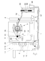
- FIG. 1 and 2 show a microtome with a base plate 1, one from the base plate 1 supported frame 2, a drive device having a handwheel 3 4, a micrometer mechanism 5 acted upon by the drive device 4 for the linear Feed of an object holding device, not shown in the figures, and one a knife holding device, also not shown in the figures, having a knife on the front of the microtome.
- the handwheel 3 is on one from the outside in the frame 2 protruding, rotatably mounted on the frame 2 shaft 6.
- the axis of rotation of the Shaft 6 rotating actuator 7 is provided.
- the actuator 7 engages displaceable on a horizontal guide 8 assigned to the micrometer mechanism 5
- the eccentricity of the actuator 7, the micrometer 5 is common with the object holding device, not shown, vertically movable, so that a cut can be made to the object.
- This horizontal guide is designed as a hardened guide shaft, the guide 10 encompasses the guide shaft as a whole. Furthermore, it is Guide shaft or horizontal guide 8 with two bearing arms, not shown on Micrometer 5 held.
- 1 and 2 also show that between the bearing of the Handwheel 3 bearing roller 6 and the actuator 7 associated with the handwheel 3 Leveling compound 12 is provided. With regard to their function is on referenced the general part of the description. 2 shows in any case further that the balancing mass 12 of the pin 11 opposite side of the Swivel arm 9 is assigned.
- the handwheel 3 consists of a wheel disk 13 and one of the wheel disk 13 Orthogonally projecting edge 14, which in an annular groove 15 formed in the frame 2 intervenes.
- the handwheel 3 points orthogonally on the side facing the frame 2 to the frame 2 extending grooves 16 for positive engagement of a locking mechanism 17 on.
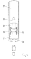
- the micrometer mechanism has an inside the cylinder 18 guided in a micrometer nut 19 by a feed mechanism rotating micrometer spindle 20.
- the micrometer spindle 20 in turn has via an external thread with a pitch of 1 mm.
- the micrometer nut 19 is designed in two parts according to the embodiment shown in FIG. 3. Between the two mother parts there is an action that pushes the mother parts apart Spring assembly 21 so that the thread flanks of the micrometer nut 19 always on the Apply thread flanks of the micrometer spindle 20 and avoid play.
- the the Part of the micrometer nut 19 facing away from the object holding device is connected to the cylinder 18 screwed so that the part of the micrometer nut facing the object device Always align 19 with force applied by the spring assembly 21 can.
- FIG. 3 further shows that the cylinder 18 on the object holding device facing side by a bearing disc centering the micrometer spindle 20 22 is closed.
- the cylinder 18th has an anti-rotation device and that the anti-rotation device fits into a groove 23 the cylinder guide in the area of the horizontal stroke, not shown in FIG. 3 Guide pin includes.
- Fig. 4 shows in an enlarged detail that the feed mechanism 24 is provided at the end of the cylinder 18 facing away from the object holding device Has friction disc 25, which has a with a feed lever 26th connected friction ring 27 cooperates.
- the feed lever 26 is vertical Movement of the micrometer mechanism 5 can be acted upon via an adjustable feed curve 28, so that the feed lever 26 over the freewheel on the micrometer spindle 20th takes hold.
- the arrangement of the friction disc 25 and Friction ring 27 both as a freewheel and for the actual feed into a defined Direction.
- the friction is is a four-point friction, 29 balls being acted upon by compression springs 30 apply pressure rollers, not shown in the figures.
- the serves Friction disk 25 as a bearing for a coarse drive gear 31.
- the delivery lever which can be seen particularly clearly in FIG. 3, is used 26 on the one hand the fine adjustment and on the other hand the trimming process.
- This The feed lever can be reset by means of a horizontally running tension spring 32.
- the for contacting the feed curve 28 has the end of the feed lever 26 a plastic insert 33 for line contact with the feed curve 28.
- the delivery curve 28 has exactly specified infeed values in every position, which can be adjusted using the infeed lever 26 are transferred to the micrometer mechanism 5.
- the position of the infeed curve 28 and thus the infeed values are in line with the infeed curve 28 connected shaft 34 from the front of the microtome via an in Fig. 5 shown adjusting wheel 35 adjustable.
- Fig. 5 further shows that the shaft 34 is rotatable on or in a dial 37 is.
- the shaft 34 extends through the dial 37, the Rotation of the shaft 34 by stops on both sides due to one in the dial 37 trained slot 38 is limited.
- the position of the cutting thickness infeed is according to the embodiment shown in Fig. 5 of a section thickness setting via a gear 39 on the shaft 34 with a second gear 40 fixed and reproduced via a viewing window, not shown, above the dial. Due to the arrangement of the gears 39, 40 selected here, a defined one is defined Reduction achieved by simply adjusting the thickness of the cut Knob 41 allows.
- This Trimming device 42 has one provided directly on frame 2 at the front left in FIG Fig. 1 only indicated trim lever 43.
- the trim device 42 is during retreat can be activated at the upper feed point of the micrometer device and has three fixed trim levels of 10, 20 and 30 m.
- the trim device further includes a trim lever with a trim curve having rotatable locking disc 44 connecting trim shaft 45, which in particular 1 can be seen.
- the locking disc 44 or trim curve is used for the system of the delivery lever 26, this being the one to be in contact with the delivery curve 28 opposite part of the delivery lever 26 is.
- the micrometer mechanism has one Retraction mechanism to retract approximately 100 m after cutting. Of the Treatment is predetermined by a vertically moving sliding element 46 Position can be triggered.
- a retraction fork 47 is by means of an axle with a bearing slidable against the micrometer spindle 20, whereby the micrometer spindle 20 against the force of the spring assembly 21 shown in Fig. 3 - against the feed direction, i.e. backwards - is pressed.
- the retraction fork 47 is flattened with two, top and at the bottom of the micrometer mechanism 5, bolts 48 are positively connected, see above that retraction is already achieved by slight twisting.
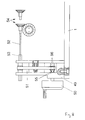
- a rough drive indicated in Fig. 8 is provided.
- base plate 1 On the left side of the For this purpose, base plate 1 is provided with a bearing block 49 which can also be seen in FIGS. 1 and 2, which is shown in detail in FIG. 8 in particular.
- the bearing block 49 has a coarse drive wheel 50, the rotational movement of which via a toothed belt 51 flexible shaft 52 is transmitted.
- the flexible shaft 52 has an end in a square profile 53 engaging a square guide for length compensation, i.e. the Square profile 53 can extend axially through the bearing over its length move.
- the rotary movement of the flexible shaft 52 is via an end on the micrometer mechanism 5 provided bevel gear pair 54 to the micrometer spindle 20.
- a slip clutch 55 is provided on the coarse drive wheel 50.
- the slip clutch 55 works with spring-loaded balls 56.
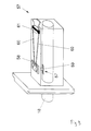
- a collision protection shown in Fig. 9 provided that the further delivery out of operation.
- Collision protection has a lever system 57 acting on the micrometer mechanism 5, which pivots the delivery lever 26 out of the delivery zone. This is on the bottom a sliding element 58 is attached to the cylinder guide.
- a driver 59 on the Sliding element 58 protrudes into a groove on the cylinder 18, so that the horizontal movement is transmitted to a toothed belt wheel 61 via a spring-loaded toothed belt 60.
- a Trigger formed on toothed belt wheel 61 then pushes one on feed lever 26 provided bolts to the side, whereby the feed lever 26 from the area of Infeed curve is pressed.
Landscapes
- Physics & Mathematics (AREA)
- Health & Medical Sciences (AREA)
- Life Sciences & Earth Sciences (AREA)
- Chemical & Material Sciences (AREA)
- Analytical Chemistry (AREA)
- Biochemistry (AREA)
- General Health & Medical Sciences (AREA)
- General Physics & Mathematics (AREA)
- Immunology (AREA)
- Pathology (AREA)
- Sampling And Sample Adjustment (AREA)
Description
- Fig. 1
- in einer schematischen Darstellung ein Ausführungsbeispiel eines erfindungsgemäßen Mikrotoms von der Rückseite, wobei sich das Mikrometerwerk in einer unteren Position des Vertikalhubs befindet,
- Fig. 2
- den Gegenstand aus Fig. 1 unter einem anderen Winkel, wobei sich das Mikrometerwerk in einer oberen Position des Vertikalhubs befindet,
- Fig. 3
- in einer schematischen Darstellung den Zylinder mit Mikrometermutter und Spindel des Mikrometerwerks,
- Fig. 4
- in einer schematischen Darstellung, vergrößert, einen Teil des Vorschubmechanismus nebst Zustellhebel und Freilauf,
- Fig. 5
- in einer vergrößerten Draufsicht die von der Vorderseite des Mikrotoms über ein Stellrad vorzunehmende Schnmittdickeneinstellung,
- Fig. 6
- in einer schematischen Seitenansicht einen zur Vermeidung einer Beschädigung an Objekt und Messer dienenden Rückzugmechanismus,
- Fig. 7
- ein Detail des in Fig. 6 gezeigten Rückzugmechanismus in vergrößerter Darstellung,
- Fig. 8
- in einer schematischen Darstellung die einen Grobtrieb betreffenden Bauteile und
- Fig. 9
- in einer schematischen Darstellung die einen Kollisionsschutz betreffenden Bauteile.
Claims (10)
- Mikrotom mit einer Grundplatte (1), einem von der Grundplatte (1) getragenen Gestell (2), einer ein Handrad (3) aufweisenden Antriebseinrichtung (4), einem von der Antriebseinrichtung (4) beaufschlagten, vertikal geführten Mikrometerwerk (5) für den linearen Vorschub einer Objekthalteeinrichtung und einer ein Messer aufweisenden Messerhalteeinrichtung, wobei das Handrad (3) auf einer von außen in das Gestell (2) hineinragenden, am Gestell (2) drehbar gelagerten Welle (6) befestigt und je Umdrehung des Handrads (3) ein die Objekthalteeinrichtung tragender Zylinder (18) des Mikrometerwerks (5) um einen einstellbaren Betrag in Richtung der Messerhalteeinrichtung bewegbar ist,
wobei am freien Ende der Welle (6) - innerhalb des Gestells (2) - ein die Drehachse der Welle (6) umlaufendes Betätigungsorgan (7) vorgesehen ist, wobei das Betätigungsorgan (7) verschiebbar auf eine dem Mikrometerwerk (5) zugeordnete Horizontalführung (8) greift und wobei das Mikrometerwerk (5) gemeinsam mit der Objekthalteeinrichtung entsprechend der Exzentrizität des Betätigungsorgans (7) vertikal bewegbar ist,
dadurch gekennzeichnet, daß die Horizontalführung (8) als gehärtete Führungswelle ausgebildet ist und daß die Führung (10) als Führungsbuchse ausgebildet ist und die Führungswelle zumindest weitgehend umgreift. - Mikrotom nach Anspruch 1, dadurch gekennzeichnet, daß das Betätigungsorgan (7) einen vorzugsweise an einem Schwenkarm (9) exzentrisch zur Drehachse der Welle (6) angeordneten, in eine ggf. einstellbare Führung (10) greifenden Stift (11) umfaßt und daß die Führung (10) auf der Horizontalführung (8) läuft.
- Mikrotom nach Anspruch 1 oder 2, dadurch gekennzeichnet, daß die Führungswelle mit vorzugsweise zwei Lagerarmen am Mikrometerwerk (5) gehalten ist.
- Mikrotom nach einem der Ansprüche 1 bis 3, dadurch gekennzeichnet, daß die Zylinderführung mit einem Kreuzrollenführungssystem am Gestell (2) befestigt ist und neben dem Zylinder (18) mit einer Mikrometerspindel (29) einen Vorschubmechanismus (24) lagert.
- Mikrotom nach Anspruch 4, dadurch gekennzeichnet, daß die Kreuzrollenführung zur Gewährleistung einer hinreichenden Stabilität und eines gleichmäßigen Vertikalhubs bewußt überdimensioniert ist.
- Mikrotom nach einem der Ansprüche 1 bis 5, dadurch gekennzeichnet, daß eine Trimmeinrichtung (42) zur Annäherung der Objekthalteeinrichtung an das Messer in kleinen vorgebbaren Schritten vorgesehen ist, wobei die Trimmeinrichtung (42) direkt am Gestell (2) mit einem vorzugsweise vorne links vorgesehenen Trimmhebel (43) angeordnet und während des Rückzugs, vorzugsweise am unteren Zustellpunkt, aktivierbar ist.
- Mikrotom nach Anspruch 6, dadurch gekennzeichnet, daß die Trimmeinrichtung (42) fest vorgebbare Trimmstufen, vorzugsweise mit 10, 20 und 30 Mikrometern, aufweist und eine den Trimmhebel (43) mit einer eine Trimmkurve aufweisenden drehbaren Rastscheibe (44) verbindende Trimmwelle (45) umfaßt und daß die Rastscheibe (44) bzw. Trimmkurve zur Anlage des Zustellhebels (26) dient.
- Mikrotom nach Anspruch 4 und ggf. einem der Ansprüche 5 bis 7, dadurch gekennzeichnet, daß das Mikrometerwerk (5) einen Rückzugmechanismus zum Rückzug von vorzugsweise 100 Mikrometern nach dem Schneiden aufweist, daß der Rückzug durch ein sich vertikal bewegendes Schiebeelement (46) in einer vorgebbaren Position auslösbar ist und daß mittels einer Achse mit Lager eine Rückzuggabel (47) gegen die Mikrometerspindel (20) schiebbar ist, wodurch die Mikrometerspindel (20) gegen die Kraft eines Federpakets (21) entgegen der Zustellrichtung - nach hinten - gedrückt wird, wobei die Rückzuggabel (47) mit zwei abgeflachten, oben und unten am Mikrometerwerk (5) gelagerten Bolzen (48) formschlüssig verbunden ist und daß durch geringe Verdrehung der Rückzug erreicht wird.
- Mikrotom nach Anspruch 4 und ggf. einem der Ansprüche 5 bis 8, dadurch gekennzeichnet, daß zur schnellen Überbrückung des Horizontalhubs und zur groben Annäherung an das Messer ein direkt auf die Mikrometerspindel (20) wirkender Grobtrieb vorgesehen ist, daß vorzugsweise auf der der Handrad (3) abgewandten Seite der Grundplatte (2), insbesondere in der vordersten Position, ein Lagerblock (49) mit einem Grobtriebrad (50) vorgesehen ist und daß die Drehbewegung des Grobtriebrades (50) über einen sich in zwei Kreuzgelenken bewegenden Vierkantstab zum Längenausgleich vorzugsweise auf ein Riemenrad übertragen wird, wobei die Drehbewegung des Riemenrades über einen Zahnriemen (51) auf ein zweites, am Mikrometerwerk (5) befestigtes Zahnriemenrad auf die Mikrometerspindel (20) oder daß die Drehbewegung des Grobtriebrades (50) über einen Zahnriemen (51) auf eine biegsame Welle (52) übertragen wird und wobei die biegsame Welle (52) endseitig ein in eine Vierkantführung greifendes Vierkantprofil (53) zum Längenausgleich aufweist.
- Mikrotom nach Anspruch 9, dadurch gekennzeichnet, daß die Drehbewegung der biegsamen Welle (52) über eine endseitig am Mikrometerwerk (5) vorgesehene Kegelradpaarung (54) auf die Mikrometerspindel (20) übertragbar ist, wobei zur Vermeidung einer Beschädigung bei Erreichen des Endanschlages auf der Achse am Grobtriebrad (50) eine Rutschkupplung (55) vorgesehen ist und wobei die Rutschkupplung (55) mit federgelagerten Kugeln (56) arbeitet und gleichzeitig eine Anti-Blockier-Einrichtung dargestellt, falls ein Überbrücken der Rutschkupplung durch nach innen Drücken des Grobtriebrads (50) und in die gewünschte Drehrichtung Drehen notwendig ist.
Applications Claiming Priority (3)
| Application Number | Priority Date | Filing Date | Title |
|---|---|---|---|
| DE4339071 | 1993-11-16 | ||
| DE4339071A DE4339071A1 (de) | 1993-11-16 | 1993-11-16 | Mikrotom |
| PCT/DE1994/001358 WO1995014219A1 (de) | 1993-11-16 | 1994-11-17 | Mikrotom |
Publications (2)
| Publication Number | Publication Date |
|---|---|
| EP0729566A1 EP0729566A1 (de) | 1996-09-04 |
| EP0729566B1 true EP0729566B1 (de) | 1999-03-17 |
Family
ID=6502698
Family Applications (1)
| Application Number | Title | Priority Date | Filing Date |
|---|---|---|---|
| EP95900638A Expired - Lifetime EP0729566B1 (de) | 1993-11-16 | 1994-11-17 | Mikrotom |
Country Status (4)
| Country | Link |
|---|---|
| EP (1) | EP0729566B1 (de) |
| AU (1) | AU8139594A (de) |
| DE (2) | DE4339071A1 (de) |
| WO (1) | WO1995014219A1 (de) |
Families Citing this family (7)
| Publication number | Priority date | Publication date | Assignee | Title |
|---|---|---|---|---|
| DE10244687A1 (de) | 2002-09-24 | 2004-04-01 | Hirt, Rüdiger | Rotationsmikrotom |
| DE102010046498B3 (de) | 2010-09-24 | 2011-12-15 | Hans Heid | Schneidehubverstellung eines Rotationsmikrotoms |
| DE102011112450C5 (de) | 2011-09-05 | 2015-04-30 | Pfm Medical Ag | Rotationsmikrotom mit Blockiereinrichtung |
| DE102014005445B3 (de) * | 2014-04-11 | 2015-01-29 | Hans Heid | Mikrotom und Verfahren zum Betrieb eines Mikrotoms |
| CN104833541B (zh) * | 2015-05-20 | 2017-07-25 | 金华市益迪医疗设备有限公司 | 一种手动类生物组织切片机夹头自动进退机构 |
| DE102019213363B4 (de) * | 2019-09-03 | 2023-06-15 | Pfm Medical Ag | Mikrotom |
| CN115446883A (zh) * | 2022-09-27 | 2022-12-09 | 广州秀威科技有限公司 | 可自由调节手轮力度的切片机 |
Family Cites Families (14)
| Publication number | Priority date | Publication date | Assignee | Title |
|---|---|---|---|---|
| DE45504C (de) * | G. Baltzar und E. Zimmermann in Leipzig | Mikrotom mit festem Messer und selbstthätigem Vorschub des Objects | ||
| US3926085A (en) * | 1974-12-02 | 1975-12-16 | American Optical Corp | Specimen feed for a microtome |
| DE8100644U1 (de) * | 1981-01-14 | 1981-05-14 | Ernst Leitz Wetzlar Gmbh, 6330 Wetzlar | Mikrotomantrieb |
| DE3347238C1 (de) * | 1983-12-28 | 1985-02-28 | Parke, Davis & Co., Morris Plains, N.J. | Rotationsmikrotom |
| DE3404098C1 (de) * | 1984-02-07 | 1990-02-15 | Parke, Davis & Co., Morris Plains, N.J. | Mikrotom mit einer Objektrueckzugeinrichtung |
| DE3436531A1 (de) * | 1984-10-05 | 1986-04-10 | Ernst Leitz Wetzlar Gmbh, 6330 Wetzlar | Mikrotom |
| DE3539138C1 (de) * | 1985-11-05 | 1986-08-14 | Parke, Davis & Co., Morris Plains, N.J. | Mikrotom |
| DE3604029C1 (de) * | 1986-02-08 | 1986-09-25 | Parke, Davis & Co., Morris Plains, N.J. | Zustelleinrichtung für die Objekthalteeinrichtung eines Schlittenmikrotoms |
| DE3727975C2 (de) * | 1987-08-21 | 1995-10-19 | Leica Instr Gmbh | Spielfreier Antrieb für den Zustellmechanismus eines Mikrotoms |
| DE3806269C1 (en) * | 1988-02-27 | 1989-04-20 | Microm Laborgeraete Gmbh, 6900 Heidelberg, De | Microtome |
| DE3830725A1 (de) * | 1988-09-09 | 1990-03-22 | Leitz Wild Gmbh | Automatische arretierung der antriebseinrichtung eines mikrotoms |
| EP0544181B1 (de) * | 1991-11-28 | 1996-12-18 | MICROM LABORGERÄTE GmbH | Mikrotom |
| DE9114791U1 (de) * | 1991-11-28 | 1992-03-05 | Microm Laborgeräte GmbH, 6909 Walldorf | Mikrometerwerk für ein Mikrotom |
| JPH05256745A (ja) * | 1992-03-16 | 1993-10-05 | Feather Safety Razor Co Ltd | ミクロトーム |
-
1993
- 1993-11-16 DE DE4339071A patent/DE4339071A1/de not_active Ceased
-
1994
- 1994-11-17 WO PCT/DE1994/001358 patent/WO1995014219A1/de not_active Ceased
- 1994-11-17 EP EP95900638A patent/EP0729566B1/de not_active Expired - Lifetime
- 1994-11-17 AU AU81395/94A patent/AU8139594A/en not_active Abandoned
- 1994-11-17 DE DE59407976T patent/DE59407976D1/de not_active Expired - Lifetime
Also Published As
| Publication number | Publication date |
|---|---|
| WO1995014219A1 (de) | 1995-05-26 |
| DE4339071A1 (de) | 1995-05-18 |
| EP0729566A1 (de) | 1996-09-04 |
| AU8139594A (en) | 1995-06-06 |
| DE59407976D1 (de) | 1999-04-22 |
Similar Documents
| Publication | Publication Date | Title |
|---|---|---|
| DE3319397C2 (de) | Gelenkbeschlag für einen Sitz mit verstellbarer Rückenlehne, insbesondere Kraftfahrzeugsitz | |
| EP0326607B1 (de) | Spielfreier antrieb für den zustellmechanismus eines mikrotoms | |
| EP0504482A1 (de) | Antrieb für einen translatorisch ausfahrbaren Überrollbügel | |
| EP0239670B1 (de) | Motorgetriebene Maschine mit Drehmomenteinstellung, insbesondere elektrisches Handwerkzeug | |
| CH648264A5 (de) | Falzvorrichtung fuer rotationsdruckmaschinen. | |
| DE3342880C2 (de) | Einstellbare Drehmomentenbegrenzung für Elektrowerkzeuge | |
| DE2805881A1 (de) | Spanndorn fuer die koaxiale bearbeitung von werkstuecken mit innenverzahnung | |
| CH676214A5 (de) | ||
| DE20315172U1 (de) | Spannvorrichtung, insbesondere Papierspannvorrichtung | |
| DE4339071A1 (de) | Mikrotom | |
| AT390713B (de) | Gegenschneidenarretierung fuer einen haecksler od. dgl. zerkleinerungsmaschine | |
| DE4236085C2 (de) | Radialwalzkopf | |
| DE69702860T2 (de) | Vorrichtung zum verschieben eines teils einer maschine und ausüben einer kraft am bewegungsende | |
| DE3615381C2 (de) | Fuehrungsvorrichtung fuer den messerbalken einer schere zur blechbearbeitung | |
| DE3539335C2 (de) | ||
| DE19701049C1 (de) | Radialwalzkopf | |
| DE2148801B2 (de) | Abhebeeinrichtung für das Schneidrad einer Zahnradwälzstoßmaschine | |
| EP0212484B2 (de) | Türschliesser | |
| DE2909937A1 (de) | Schraubstock, insbesondere maschinen- schraubstock | |
| DE3012996A1 (de) | Rollenanordnung in radsatzreprofkilierungsmaschine | |
| DE9317511U1 (de) | Mikrotom | |
| DE1805566B1 (de) | Fuehrungsvorrichtung fuer Fahrzeug-Schiebefenster,insbesondere fuer Personenkraftwagen | |
| DE4015445A1 (de) | Vorrichtung zum spannen eines werkstuecktraegers | |
| EP0255609A2 (de) | Stufenlos einstellbarer Rundteiltisch | |
| WO2004037465A1 (de) | Werkzeug zum mechanischen bearbeiten von werkstücken |
Legal Events
| Date | Code | Title | Description |
|---|---|---|---|
| PUAI | Public reference made under article 153(3) epc to a published international application that has entered the european phase |
Free format text: ORIGINAL CODE: 0009012 |
|
| 17P | Request for examination filed |
Effective date: 19960617 |
|
| AK | Designated contracting states |
Kind code of ref document: A1 Designated state(s): DE |
|
| 17Q | First examination report despatched |
Effective date: 19960912 |
|
| GRAG | Despatch of communication of intention to grant |
Free format text: ORIGINAL CODE: EPIDOS AGRA |
|
| GRAG | Despatch of communication of intention to grant |
Free format text: ORIGINAL CODE: EPIDOS AGRA |
|
| GRAH | Despatch of communication of intention to grant a patent |
Free format text: ORIGINAL CODE: EPIDOS IGRA |
|
| GRAH | Despatch of communication of intention to grant a patent |
Free format text: ORIGINAL CODE: EPIDOS IGRA |
|
| GRAA | (expected) grant |
Free format text: ORIGINAL CODE: 0009210 |
|
| AK | Designated contracting states |
Kind code of ref document: B1 Designated state(s): DE |
|
| REF | Corresponds to: |
Ref document number: 59407976 Country of ref document: DE Date of ref document: 19990422 |
|
| PLBE | No opposition filed within time limit |
Free format text: ORIGINAL CODE: 0009261 |
|
| STAA | Information on the status of an ep patent application or granted ep patent |
Free format text: STATUS: NO OPPOSITION FILED WITHIN TIME LIMIT |
|
| 26N | No opposition filed | ||
| REG | Reference to a national code |
Ref country code: DE Ref legal event code: R082 Ref document number: 59407976 Country of ref document: DE Representative=s name: ULLRICH & NAUMANN, DE |
|
| REG | Reference to a national code |
Ref country code: DE Ref legal event code: R082 Ref document number: 59407976 Country of ref document: DE Representative=s name: PATENT- UND RECHTSANWAELTE ULLRICH & NAUMANN P, DE Effective date: 20110928 Ref country code: DE Ref legal event code: R081 Ref document number: 59407976 Country of ref document: DE Owner name: PFM MEDICAL AG, DE Free format text: FORMER OWNERS: GANTER, WALTER, 69190 WALLDORF, DE; PFM PRODUKTE FUER DIE MEDIZIN AG, 50996 KOELN, DE Effective date: 20110928 Ref country code: DE Ref legal event code: R081 Ref document number: 59407976 Country of ref document: DE Owner name: GANTER, WALTER, DE Free format text: FORMER OWNERS: GANTER, WALTER, 69190 WALLDORF, DE; PFM PRODUKTE FUER DIE MEDIZIN AG, 50996 KOELN, DE Effective date: 20110928 Ref country code: DE Ref legal event code: R081 Ref document number: 59407976 Country of ref document: DE Owner name: GANTER, WALTER, DE Free format text: FORMER OWNER: WALTER GANTER, PFM PRODUKTE FUER DIE MEDIZIN AG, , DE Effective date: 20110928 Ref country code: DE Ref legal event code: R081 Ref document number: 59407976 Country of ref document: DE Owner name: PFM MEDICAL AG, DE Free format text: FORMER OWNER: WALTER GANTER, PFM PRODUKTE FUER DIE MEDIZIN AG, , DE Effective date: 20110928 |
|
| PGFP | Annual fee paid to national office [announced via postgrant information from national office to epo] |
Ref country code: DE Payment date: 20140130 Year of fee payment: 20 |
|
| REG | Reference to a national code |
Ref country code: DE Ref legal event code: R071 Ref document number: 59407976 Country of ref document: DE |
|
| REG | Reference to a national code |
Ref country code: DE Ref legal event code: R071 Ref document number: 59407976 Country of ref document: DE |