EP0728905B1 - Dispositif de montage d'un tube d'enroulement notamment d'un volet roulant, comportant des moyens de fixation et de verrouillage - Google Patents
Dispositif de montage d'un tube d'enroulement notamment d'un volet roulant, comportant des moyens de fixation et de verrouillage Download PDFInfo
- Publication number
- EP0728905B1 EP0728905B1 EP96440020A EP96440020A EP0728905B1 EP 0728905 B1 EP0728905 B1 EP 0728905B1 EP 96440020 A EP96440020 A EP 96440020A EP 96440020 A EP96440020 A EP 96440020A EP 0728905 B1 EP0728905 B1 EP 0728905B1
- Authority
- EP
- European Patent Office
- Prior art keywords
- base
- plate
- opening
- tenons
- locking
- Prior art date
- Legal status (The legal status is an assumption and is not a legal conclusion. Google has not performed a legal analysis and makes no representation as to the accuracy of the status listed.)
- Expired - Lifetime
Links
- 210000000056 organ Anatomy 0.000 claims description 11
- 239000000463 material Substances 0.000 claims description 3
- 230000006835 compression Effects 0.000 claims description 2
- 238000007906 compression Methods 0.000 claims description 2
- 238000002788 crimping Methods 0.000 claims description 2
- 238000000465 moulding Methods 0.000 claims description 2
- 230000000750 progressive effect Effects 0.000 claims description 2
- 230000037431 insertion Effects 0.000 claims 2
- 238000003780 insertion Methods 0.000 claims 2
- 230000004308 accommodation Effects 0.000 claims 1
- 230000000284 resting effect Effects 0.000 claims 1
- 229920002994 synthetic fiber Polymers 0.000 abstract description 2
- 238000004804 winding Methods 0.000 description 15
- 238000009434 installation Methods 0.000 description 3
- 238000013016 damping Methods 0.000 description 2
- 230000000694 effects Effects 0.000 description 1
- 238000009432 framing Methods 0.000 description 1
- 238000004519 manufacturing process Methods 0.000 description 1
- 239000002184 metal Substances 0.000 description 1
- 238000000034 method Methods 0.000 description 1
- 238000005096 rolling process Methods 0.000 description 1
- 238000013024 troubleshooting Methods 0.000 description 1
Images

Classifications
-
- E—FIXED CONSTRUCTIONS
- E06—DOORS, WINDOWS, SHUTTERS, OR ROLLER BLINDS IN GENERAL; LADDERS
- E06B—FIXED OR MOVABLE CLOSURES FOR OPENINGS IN BUILDINGS, VEHICLES, FENCES OR LIKE ENCLOSURES IN GENERAL, e.g. DOORS, WINDOWS, BLINDS, GATES
- E06B9/00—Screening or protective devices for wall or similar openings, with or without operating or securing mechanisms; Closures of similar construction
- E06B9/02—Shutters, movable grilles, or other safety closing devices, e.g. against burglary
- E06B9/08—Roll-type closures
- E06B9/11—Roller shutters
- E06B9/17—Parts or details of roller shutters, e.g. suspension devices, shutter boxes, wicket doors, ventilation openings
- E06B9/174—Bearings specially adapted therefor
Definitions
- the present invention relates to a device for mounting a winding tube of a roller shutter comprising an apron laterally guided in slides and connected by its edge higher than said winding tube, the fixing of which in the framing of an opening is carried out by the intermediary two corresponding side support cheeks, one of which less, is able to receive, in an opening quadrangular a base with a corresponding shape constituting a support element for the end of the tube winding.
- Said quadrangular opening comprises means for fixing the base to said side cheeks.
- a device of this type is known from the document FR-A-2.693.227 more particularly describing a set of roller shutter supports also carried out by through a side cheek and a base, defined at to lodge in an opening of said cheek and to be secured by fixing means.
- Such a design has the major drawback of not allow axial engagement of the base in its housing but, on the contrary, to require an oblique introduction of one of the attachment tabs of said base under that corresponding cheek, then, in a movement of straightening and lowering, the introduction of the other leg hooking the base under the other legs of the cheek.
- Such manipulations do not facilitate the task of the operator which are moreover penalizing in time of workforce.
- the document FR-A-2,550,270 describes a device for mounting of a rotating winding tube of a rolling shutter which tube is supported by two side support cheeks able to be crossed right through by an axis on the one hand, internally, with a support bearing in connection with the tube, and on the other hand, by a base located on the external face of said cheek and itself comprising means of connection with a body of external control, a pulley manually controlled by a strap in this case.
- this base has a central bore intended to receive a bearing also by means elastic snap.
- the object of the present invention is to remedy all of these disadvantages and concerns, for this purpose, a device for mounting a winding tube of a roller shutter comprising an apron guided laterally in slides and connected, by its upper edge, to said winding tube whose fixing in the frame of an opening (not shown) is carried out by means of two side support cheeks correspondents of which at least one is able to receive, in a quadrangular opening a shaped base corresponding constituting a support element of the end of the winding tube, said quadrangular opening comprising means for fixing the base to said side cheeks, characterized in that the fixing means of the base in the corresponding opening of the cheek are consisting of at least one mortise made on each of two parallel sides of the opening and able to engage on a corresponding lug of the base or vice versa, the actual asset being obtained through at least one locking member.
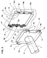
- the figure 1 shows the end of an electrically driven tube 1 and intended for the winding and unwinding of an apron of a roller shutter.
- the electric drive motor could for example be a tubular type brake motor engaged so as in this end of the tube 1.
- each of these side supports cheeks 2 receives, in an opening quadrangular 4, a base 3, of corresponding shape and constituting a support element for the ends of the tube winding 1.
- these side support cheeks 2 have fixing means arranged in the opening quadrangular 4 allowing them, precisely, to accommodate fixedly such a base 3. At least one of these is also intended to receive control means in tube rotation 1.
- the means for fixing the base 3 in the corresponding opening 4 of the cheek 2 are constituted by at least one mortise 5, 6, 7, 8 made on each of two parallel sides 4a, 4b, of the opening 4 and able to engage on a corresponding tenon 9, 10, 11, 12, of the base 3 or conversely, the actual immobilization being obtained by through at least one locking member 13.
- each of the two sides parallels 4a, 4b of the opening 4 of the cheek 2 are made two mortises 5, 6, 7, 8 in which are suitable for engage two pairs of corresponding studs 9, 10, 11, 12, made in coincidence on the base 3.
- mortises 5, 6, 7, 8 of the plays 2 and the pins 9, 10, 11, 12 of the base 3 are rectangular, but the present invention is by no means limited to such a form.
- Each pair of mortises 5, 6, on each side 4a, 4b of the cheek 2 is made opposite the other pair 7, 8, the pins 9, 10, 11, 12, corresponding, of the base 3, being made in coincidence with these.
- the grooves 18, 19 made on either side of the opening 4 of cheek 2 have a length greater than the height of mortises 5, 6, 7, 8 and teeth 14 or 15 which they define so that they allow free longitudinal travel corresponding locking members 13.
- each locking member 13 is constituted by a bolt that can be operated from bottom to top and in the high of which is provided a notch 20 of dimension and of a shape corresponding to that of a top mortise 5, 7 cheek 2, the length of said bolt 13 being such that when its notch 20 is coincident with the upper mortise 5, 7, its lower end 21 does not obscure not the lower mortise 6, 8 and allows, thus, the free introduction of tenons 9, 10, 11, 12 in said mortises 5, 6, 7, 8 during assembly. Locking takes place by sliding of said targettes from top to bottom.
- each of the pins 13 comprises in a middle part a recess 25 produced in coincidence with a light 26, formed on a front part of the cheek 2 of so as to allow the introduction of a tool 27 intended for actuation, downwards or upwards, of the bolt 13 in order to bring it into a position respectively, locking and unlocking.
- each locking member is constituted by a rod 13A previously arranged in each of the grooves 18, 19 of lateral sides 4a, 4b of the opening 4 of the cheek 2.
- This rod 13A may act against a recall body elastic 30 with which it is associated and which is arranged against the bottom of said groove 18, 19. The depth of this is such as to allow the housing of the whole while by offering it a lateral play able to allow the retraction total elastic of the rod 13A at the passage of the front tenons 9A, 10A, 11A, 12A, of the base 3A, when it is mounted in the play 2.
- the locking rod 13A is a rod cylindrical.
- the grooves 18, 19 comprise means for retaining the rod 13A lock on which acts in permanent thrust the elastic member 30.
- These retaining means are constituted by crimping the external edges 18A, 18B of the said grooves 18, 19 and against which the elastic member 30 permanently pushes rod 13A before mounting base 3A.
- the front pins 9A, 10A, 11A, 12A of the base 3A have a chamfer 31 allowing an attack and a progressive erasure of the locking rod 13A during from their passage at the start of the assembly operation. They thus act in compression on the elastic member 30 arranged in each groove 18, 19, until each rod 13A snaps into the corresponding grooves 23, 24 delimited respectively by the tenons 9, 9A, 10, 10A, 11, 11A and 12, 12A, in a final assembly phase.
- a clearance 32 is arranged on a front part of the cheek 2, so to allow the introduction of a tool intended for actuation in a lateral direction of the rod 13A for its unlocking.
- the elastic member 30 is a leaf spring preferably of wavy shape comprising two symmetrical end bends 30a and one central 30b in permanent support, both in the bottom of the grooves 18, 19 and on the locking rod 13A.
- the base 3; 3A constitutes a box containing the means for controlling the rotation of the tube 1.
- this base 3; 3A is attached to one end of the winding tube 1.
- a base 3; 3A can be placed at each end of the tube 1, at least one of the latter comprising a telescopic end part, suitable for allowing precise length of the assembly relative to the width of the framework for which it is intended.
- vibration damping means and noise in the form of a flexible interface, preventing, specifically, that the vibrations or the noise produced by the winding tube 1 during rotation or by the drive means such as drive means, act on this tube 1.
- this flexible interface can be presented in the form of a flexible seal covering the periphery the base 3; 3A and / or the walls delimiting the opening 4 in cheek 2.
- this base 3; 3A and / or the cheek 2 made of synthetic material by a molding process.
- this base 3; 3A and / or cheek 2 can be made of bi-material, one of which has flexibility sufficient to fulfill the functions of damping means of noise and vibration.
- this material of a certain flexibility then comes to define the periphery of the opening 4 in the cheek 2 and / or the periphery of the base 3; 3A.
Landscapes
- Engineering & Computer Science (AREA)
- Structural Engineering (AREA)
- Architecture (AREA)
- Civil Engineering (AREA)
- Operating, Guiding And Securing Of Roll- Type Closing Members (AREA)
- Storage Of Web-Like Or Filamentary Materials (AREA)
Description
- la figure 1 est une vue en perspective d'un dispositif de montage d'un tube d'enroulement sur une joue support représentée en cours de mise en place ;
- la figure 2 est une vue en perspective d'un dispositif selon la figure 1 après mise en place ;
- la figure 3 est une vue en perspective d'un dispositif de montage d'un tube d'enroulement sur une joue support, en cours de mise en place, selon un autre mode de réalisation de l'invention.
Claims (19)
- Dispositif de montage d'un tube d'enroulement d'un volet roulant comportant un tablier guidé latéralement dans des glissières et relié par son bord supérieur audit tube d'enroulement, dont la fixation dans l'encadrement d'une ouverture est effectuée par l'intermédiaire de deux joues supports latérales correspondantes (2) dont l'une, au moins, est à même de recevoir, dans une ouverture quadrangulaire (4), une embase (3) de forme correspondante constituant un élément de support de l'extrémité du tube d'enroulement (1), ladite ouverture quadrangulaire (4) comportant des moyens de fixation de l'embase (3) sur lesdites joues latérales (2), caractérisé en ce que lesdits moyens de fixation de l'embase (3 ; 3A) dans l'ouverture correspondante (4) de la joue (2) sont constitués par au moins une mortaise (5, 6, 7, 8) réalisée sur chacun de deux côtés parallèles (4a, 4b) de l'ouverture (4) et apte à s'engager sur un tenon correspondant (9, 10, 11, 12 ; 9A, 10A, 11A, 12A) de l'embase (3 ; 3A) ou inversement, l'immobilisation effective étant obtenue par l'intermédiaire d'au moins un organe de verrouillage (13 ; 13A).
- Dispositif selon la revendication 1, caractérisé en ce que, sur chacun des deux côtés parallèles (4a, 4b) de l'ouverture (4) de la joue (2) sont réalisées deux mortaises (5, 6, 7, 8) dans lesquelles sont aptes à s'engager deux tenons correspondants (9, 10, 11, 12 ; 9A, 10A, 11A, 12A) réalisés en coïncidence sur l'embase (3 ; 3A).
- Dispositif selon la revendication 2, caractérisé en ce que les mortaises (5, 6, 7, 8) de la joue (2) et les tenons (9, 10, 11, 12 ; 9A, 10A, 11A, 12A) de l'embase (3 ; 3A) sont rectangulaires.
- Dispositif selon la revendication 2 ou 3, caractérisé en ce que chacune des paires de mortaises (5, 6) de chaque côté latéral de la joue (2) est réalisée en vis-à-vis de l'autre paire (7, 8), les tenons (9, 10, 11, 12 ; 9A, 10A, 11A, 12A) correspondants, de l'embase (3 ; 3A), étant réalisés en coïncidence de celles-ci.
- Dispositif selon l'une des revendications 1 à 4, caractérisé en ce que les deux mortaises (5, 6) et (7, 8) réalisées sur chaque côté latéral (4a, 4b) de l'ouverture (4) de la joue (2) délimitent, entre elles une dent (14 ou 15) apte à se loger dans des créneaux correspondants (16 ou 17) délimités par les deux tenons (9, 10 ou 11, 12 ; 9A, 10A, 11A, 12A) réalisés sur chaque côté latéral (3a, 3b) de l'embase (3 ; 3A).
- Dispositif selon l'une des revendications 1 à 5, caractérisé en ce que dans l'épaisseur des côtés latéraux (4a, 4b) et dans celle des tenons correspondants (9, 10, 11, 12 ; 9A, 10A, 11A, 12A) de l'embase (3, 3A) sont réalisées respectivement des rainures longitudinales (18, 19) et (23, 24) en coïncidence, de profondeur au moins égale à la hauteur des mortaises (5, 6, 7, 8) et des dents (14 ou 15) de la joue (2) et à la hauteur des tenons (9, 10, 11, 12 ; 9A, 10A, 11A, 12A) et des créneaux (16, 17) de l'embase (3, 3A), lesdites rainures de l'un et l'autre des éléments étant destinées au logement des organes de verrouillage (13 ; 13A).
- Dispositif selon la revendication 6, caractérisé en ce que les rainures (18, 19), réalisées de part et d'autre de l'ouverture (4) de la joue (2) ont une longueur supérieure à la hauteur des mortaises (5, 6, 7, 8) et des dents (14 ou 15) de sorte qu'elles permettent le libre débattement longitudinal des organes de verrouillage correspondants (13).
- Dispositif selon la revendication 7, caractérisé en ce que chaque organe de verrouillage (13) est constitué par une targette, actionnable de bas en haut, et dans la partie haute de laquelle est ménagée une échancrure (20) de dimension et de forme correspondantes à celles d'une mortaise supérieure (5, 7) de la joue (2), la longueur de ladite targette étant telle que lorsque son échancrure (20) est en coïncidence avec la mortaise supérieure (5, 7), son extrémité inférieure (21) n'occulte pas la mortaise inférieure (6, 8) et permet, ainsi, la libre introduction des tenons (9, 10, 11, 12) dans les mortaises (5, 6, 7, 8) lors du montage, le verrouillage s'effectuant par glissement desdites targettes (13), ayant pour effet de décaler l'échancrure (20) en amenant, d'une part, l'extrémité supérieure (22) de la targette (13), à la fois, devant la mortaise correspondante (5, 7) de la joue (2) et dans la rainure (23, 24) du tenon correspondant (9, 11) et, d'autre part, son extrémité inférieure (21) devant la mortaise inférieure (6, 8) et dans la rainure (23, 24) du tenon correspondant (10, 12).
- Dispositif selon la revendication 8, caractérisé en ce que chacune des targettes (13) comporte dans une partie médiane un évidement (25) réalisé en coïncidence d'une lumière (26) aménagée sur une partie frontale de la joue (2) de manière à permettre l'introduction d'un outil (27) destiné à l'actionnement vers le bas ou vers le haut de la targette (13) en vue de l'amener dans une position, respectivement, de verrouillage et de déverrouillage.
- Dispositif selon la revendication 6, caractérisé en ce que chaque organe de verrouillage est constitué par une tige (13A), notamment cylindrique préalablement disposée dans chacune des rainures (18, 19) des côtés latéraux (4a, 4b) de l'ouverture (4) de la joue (2) et susceptible d'agir à l'encontre d'un organe de rappel élastique (30) avec lequel elle est associée et qui est disposé contre le fond de ladite rainure (18, 19), la profondeur de celle-ci étant telle à permettre le logement de l'ensemble tout en lui offrant un jeu latéral apte à permettre l'escamotage élastique total de la tige (13A) au passage des tenons frontaux (9A, 10A, 11A, 12A) de l'embase (3A), lors de son montage dans la joue (2).
- Dispositif selon la revendication 10, caractérisé en ce que les rainures (18, 19) comportent des moyens de retenue de la tige de verrouillage (13A) sur laquelle agit en poussée permanente l'organe élastique (30) et qui sont constitués par un sertissage des arêtes externes (18a, 18b) desdites rainures (18, 19) et contre lesquelles l'organe élastique (30) pousse de manière permanente la tige (13A).
- Dispositif selon l'une des revendications 10 et 11, caractérisé en ce que les tenons frontaux (9A, 10A, 11A, 12A) de l'embase (3A) comportent un chanfrein (31) permettant une attaque et un effacement progressif de la tige de verrouillage (13A) lors de leur passage, au début de l'opération de montage, et agissant en compression sur l'organe élastique (30) jusqu'à ce que chaque tige (13A) disposée dans chaque rainure (18, 19) s'enclenche élastiquement dans les rainures correspondantes (23, 24) délimitées respectivement par les tenons (9 9A, 10 ; 10A, 11 ; 11A, 12 ; 12A), dans une phase finale de montage.
- Dispositif selon l'une des revendications 10 à 12, caractérisé en ce qu'un dégagement (32) est aménagé dans une partie frontale de la joue (2) , de manière à permettre l'introduction d'un outil destiné à l'actionnement dans un sens latéral de la tige (13A) en vue de son déverrouillage.
- Dispositif selon l'une des revendications 10 à 12, caractérisé en ce que l'organe élastique (30) est un ressort à lame préférentiellement ondulée comportant deux cambrures d'extrémité symétrique (30a) et une centrale (30b) en appui permanent à la fois dans le fond des rainures (18, 19) et sur la tige de verrouillage (13A).
- Dispositif selon l'une des revendications précédentes, caractérisé en ce que l'embase (3 ; 3A) constitue un boítier renfermant les moyens de commande en rotation du tube d'enroulement (1).
- Dispositif selon l'une des revendications précédentes, caractérisé en ce que l'embase (3 ; 3A) est solidaire d'une extrémité du tube d'enroulement (1).
- Dispositif selon l'une des revendications précédentes, caractérisé en ce qu'une embase (3 ; 3A) est disposée à chaque extrémité du tube (1), au moins l'une de celle-ci comportant une partie d'extrémité télescopique apte à permettre une mise à longueur précise de l'ensemble, par rapport à la largeur de l'encadrement auquel il est destiné.
- Dispositif selon l'une des revendications précédentes, caractérisé par le fait qu'il comporte des moyens amortisseurs de vibration et de bruit sous forme d'une interface souple, tel qu'un joint souple, entre les parois de l'embase (3 ; 3A) et celles délimitant l'ouverture (4) dans la joue (2).
- Dispositif selon la revendication 18, caractérisé par le fait que l'embase (3) et/ou la joue (2) sont réalisées par moulage en bi-matière synthétique dont une, plus souple, pour constituer des moyens amortisseurs de bruit et de vibration, vient définir le pourtour de l'ouverture (4) dans la joue (2) et/ou la périphérie de l'embase (3 ; 3A).
Applications Claiming Priority (4)
| Application Number | Priority Date | Filing Date | Title |
|---|---|---|---|
| FR9502397A FR2731039A1 (fr) | 1995-02-27 | 1995-02-27 | Dispositif de montage d'un tube d'enroulement notamment d'un volet roulant, comportant des moyens de fixation et de verrouillage |
| FR9502397 | 1995-02-27 | ||
| FR9504688A FR2731040B1 (fr) | 1995-02-27 | 1995-04-13 | Dispositif de montage d'un tube d'enroulement notamment d'un volet roulant, comportant des moyens de fixation et de verrouillage |
| FR9504688 | 1995-04-13 |
Publications (2)
| Publication Number | Publication Date |
|---|---|
| EP0728905A1 EP0728905A1 (fr) | 1996-08-28 |
| EP0728905B1 true EP0728905B1 (fr) | 1999-05-19 |
Family
ID=26231790
Family Applications (1)
| Application Number | Title | Priority Date | Filing Date |
|---|---|---|---|
| EP96440020A Expired - Lifetime EP0728905B1 (fr) | 1995-02-27 | 1996-02-26 | Dispositif de montage d'un tube d'enroulement notamment d'un volet roulant, comportant des moyens de fixation et de verrouillage |
Country Status (5)
| Country | Link |
|---|---|
| EP (1) | EP0728905B1 (fr) |
| AT (1) | ATE180310T1 (fr) |
| DE (1) | DE69602474T2 (fr) |
| ES (1) | ES2132865T3 (fr) |
| FR (1) | FR2731040B1 (fr) |
Cited By (1)
| Publication number | Priority date | Publication date | Assignee | Title |
|---|---|---|---|---|
| USD444375S1 (en) | 1999-02-12 | 2001-07-03 | Velux Industri A/S | Mounting fixture for internal arrangement of a screening device on a window |
Families Citing this family (2)
| Publication number | Priority date | Publication date | Assignee | Title |
|---|---|---|---|---|
| ES2197071T3 (es) * | 1999-02-12 | 2004-01-01 | Vkr Holding A/S | Medios de soporte para un dispositivo de apantallamiento. |
| FR2802240B1 (fr) * | 1999-12-10 | 2002-01-18 | Simbac S P A | Dispositif de fixation pour un arbre d'enroulement et mecanisme de manoeuvre d'une installation de fermeture ou de protection solaire comprenant un tel dispositif |
Family Cites Families (2)
| Publication number | Priority date | Publication date | Assignee | Title |
|---|---|---|---|---|
| FR2550270B1 (fr) * | 1983-08-05 | 1988-06-03 | Accoplas Fermetures | Dispositif pour le montage et le reglage de l'arbre d'enroulement d'un volet roulant |
| FR2693227B1 (fr) * | 1992-07-01 | 1994-09-16 | Peyrichou Fermetures Henri | Ensemble de supports pour volet roulant traditionnel. |
-
1995
- 1995-04-13 FR FR9504688A patent/FR2731040B1/fr not_active Expired - Lifetime
-
1996
- 1996-02-26 AT AT96440020T patent/ATE180310T1/de not_active IP Right Cessation
- 1996-02-26 EP EP96440020A patent/EP0728905B1/fr not_active Expired - Lifetime
- 1996-02-26 DE DE69602474T patent/DE69602474T2/de not_active Expired - Lifetime
- 1996-02-26 ES ES96440020T patent/ES2132865T3/es not_active Expired - Lifetime
Cited By (1)
| Publication number | Priority date | Publication date | Assignee | Title |
|---|---|---|---|---|
| USD444375S1 (en) | 1999-02-12 | 2001-07-03 | Velux Industri A/S | Mounting fixture for internal arrangement of a screening device on a window |
Also Published As
| Publication number | Publication date |
|---|---|
| ATE180310T1 (de) | 1999-06-15 |
| DE69602474D1 (de) | 1999-06-24 |
| FR2731040B1 (fr) | 1997-12-19 |
| DE69602474T2 (de) | 1999-11-25 |
| EP0728905A1 (fr) | 1996-08-28 |
| FR2731040A1 (fr) | 1996-08-30 |
| ES2132865T3 (es) | 1999-08-16 |
Similar Documents
| Publication | Publication Date | Title |
|---|---|---|
| FR2703477A1 (fr) | Charnière, notamment pour monture de lunettes. | |
| EP1106775A1 (fr) | Dispositif de fixation pour un arbre d'enroulement et mécanisme de manoeuvre d'une installation de fermeture ou de protection solaire comprenant un tel dispositif | |
| FR2550270A1 (fr) | Dispositif pour le montage et le reglage de l'arbre d'enroulement d'un volet roulant | |
| FR2759933A1 (fr) | Dispositif a magasin pour enfoncer des elements de fixation | |
| EP0430834B1 (fr) | Caisson monobloc pour volet roulant | |
| FR2731040A1 (fr) | Dispositif de montage d'un tube d'enroulement notamment d'un volet roulant, comportant des moyens de fixation et de verrouillage | |
| FR3115809A1 (fr) | Support d’arbre de volet roulant, installation de fermeture ou de protection solaire comprenant un tel support et procédé d’assemblage associé | |
| EP2264272B1 (fr) | Dispositif de montage d'un mécanisme d'enroulement d'un moyen d'occultation et/ou d'obscurcissement d'une ouverture | |
| FR2731039A1 (fr) | Dispositif de montage d'un tube d'enroulement notamment d'un volet roulant, comportant des moyens de fixation et de verrouillage | |
| EP1160414A1 (fr) | Dispositif formant support d'extrémité pour un arbre d'enroulement, son procédé d'assemblage et mécanisme de manoeuvre d'une installation de fermeture ou de protection solaire comprenant un tel dispositif | |
| FR2806988A1 (fr) | Volet de fermeture de boite a gants ou analogues, en particulier pour vehicules automibiles | |
| FR2746715A1 (fr) | Dispositif de commande d'un flux d'air, en particulier pour une installation de chauffage et/ou climatisation de vehicule automobile | |
| EP2839087B1 (fr) | Système de verrouillage à cliquet | |
| FR2553590A1 (fr) | Ensemble a balai en carbone | |
| EP1106774A1 (fr) | Dispositif de fixation d'un organe d'entraínement et mécanisme de manoeuvre d'une installation de fermeture ou de protection solaire comprenant un tel dispositif | |
| EP1528192B1 (fr) | Ferrure de verrouillage pour ouvrant coulissant. | |
| EP1059415A1 (fr) | Enrouleur de sangle, mécanisme de manoeuvre d'un volet ou store roulant comprenant un tel enrouleur et procédé de fabrication d'un tel enrouleur | |
| EP3604051B1 (fr) | Ensemble de connexion d'un bras d'entrainement d'un balai d'essuyage a un arbre moteur d'un vehicule | |
| EP1262627B1 (fr) | Joue support de volet roulant | |
| EP0404622A1 (fr) | Dispositif de positionnement ajustable pour vitrage de véhicule automobile | |
| EP0337828A1 (fr) | Dispositif d'articulation de lattes sur le bâti d'un lit et procédé de fabrication d'un tel dispositif | |
| CH654187A5 (en) | Modular device for storing various objects | |
| EP1441155A1 (fr) | Dispositif de commande de boíte de vitesses permettant un changement de rapport accéléré, et méthode de changement de rapport associé | |
| FR2746716A1 (fr) | Dispositif de commande d'un flux d'air, notamment pour une installation de chauffage et/ou climatisation de vehicule automobile | |
| FR2697781A1 (fr) | Pare-soleil formé d'une plaque allongée avec palier de rotation monté élastiquement. |
Legal Events
| Date | Code | Title | Description |
|---|---|---|---|
| PUAI | Public reference made under article 153(3) epc to a published international application that has entered the european phase |
Free format text: ORIGINAL CODE: 0009012 |
|
| AK | Designated contracting states |
Kind code of ref document: A1 Designated state(s): AT BE CH DE ES IT LI NL |
|
| 17P | Request for examination filed |
Effective date: 19970120 |
|
| GRAG | Despatch of communication of intention to grant |
Free format text: ORIGINAL CODE: EPIDOS AGRA |
|
| 17Q | First examination report despatched |
Effective date: 19980925 |
|
| GRAG | Despatch of communication of intention to grant |
Free format text: ORIGINAL CODE: EPIDOS AGRA |
|
| GRAH | Despatch of communication of intention to grant a patent |
Free format text: ORIGINAL CODE: EPIDOS IGRA |
|
| GRAH | Despatch of communication of intention to grant a patent |
Free format text: ORIGINAL CODE: EPIDOS IGRA |
|
| GRAA | (expected) grant |
Free format text: ORIGINAL CODE: 0009210 |
|
| AK | Designated contracting states |
Kind code of ref document: B1 Designated state(s): AT BE CH DE ES IT LI NL |
|
| PG25 | Lapsed in a contracting state [announced via postgrant information from national office to epo] |
Ref country code: NL Free format text: LAPSE BECAUSE OF FAILURE TO SUBMIT A TRANSLATION OF THE DESCRIPTION OR TO PAY THE FEE WITHIN THE PRESCRIBED TIME-LIMIT Effective date: 19990519 Ref country code: AT Free format text: LAPSE BECAUSE OF FAILURE TO SUBMIT A TRANSLATION OF THE DESCRIPTION OR TO PAY THE FEE WITHIN THE PRESCRIBED TIME-LIMIT Effective date: 19990519 |
|
| REF | Corresponds to: |
Ref document number: 180310 Country of ref document: AT Date of ref document: 19990615 Kind code of ref document: T |
|
| REG | Reference to a national code |
Ref country code: CH Ref legal event code: EP |
|
| REF | Corresponds to: |
Ref document number: 69602474 Country of ref document: DE Date of ref document: 19990624 |
|
| REG | Reference to a national code |
Ref country code: ES Ref legal event code: FG2A Ref document number: 2132865 Country of ref document: ES Kind code of ref document: T3 |
|
| PG25 | Lapsed in a contracting state [announced via postgrant information from national office to epo] |
Ref country code: BE Free format text: LAPSE BECAUSE OF NON-PAYMENT OF DUE FEES Effective date: 20000228 |
|
| PG25 | Lapsed in a contracting state [announced via postgrant information from national office to epo] |
Ref country code: LI Free format text: LAPSE BECAUSE OF NON-PAYMENT OF DUE FEES Effective date: 20000229 Ref country code: CH Free format text: LAPSE BECAUSE OF NON-PAYMENT OF DUE FEES Effective date: 20000229 |
|
| PLBE | No opposition filed within time limit |
Free format text: ORIGINAL CODE: 0009261 |
|
| STAA | Information on the status of an ep patent application or granted ep patent |
Free format text: STATUS: NO OPPOSITION FILED WITHIN TIME LIMIT |
|
| 26N | No opposition filed | ||
| BERE | Be: lapsed |
Owner name: S.A. BUBENDORFF Effective date: 20000228 |
|
| REG | Reference to a national code |
Ref country code: CH Ref legal event code: PL |
|
| PGFP | Annual fee paid to national office [announced via postgrant information from national office to epo] |
Ref country code: ES Payment date: 20150225 Year of fee payment: 20 Ref country code: IT Payment date: 20150226 Year of fee payment: 20 Ref country code: DE Payment date: 20150219 Year of fee payment: 20 |
|
| REG | Reference to a national code |
Ref country code: DE Ref legal event code: R071 Ref document number: 69602474 Country of ref document: DE |
|
| REG | Reference to a national code |
Ref country code: ES Ref legal event code: FD2A Effective date: 20160602 |
|
| PG25 | Lapsed in a contracting state [announced via postgrant information from national office to epo] |
Ref country code: ES Free format text: LAPSE BECAUSE OF EXPIRATION OF PROTECTION Effective date: 20160227 |