EP0727598A2 - Dispositif de commande pour transmission - Google Patents
Dispositif de commande pour transmission Download PDFInfo
- Publication number
- EP0727598A2 EP0727598A2 EP96100996A EP96100996A EP0727598A2 EP 0727598 A2 EP0727598 A2 EP 0727598A2 EP 96100996 A EP96100996 A EP 96100996A EP 96100996 A EP96100996 A EP 96100996A EP 0727598 A2 EP0727598 A2 EP 0727598A2
- Authority
- EP
- European Patent Office
- Prior art keywords
- pressure
- control
- clutch
- reverse drive
- reverse
- Prior art date
- Legal status (The legal status is an assumption and is not a legal conclusion. Google has not performed a legal analysis and makes no representation as to the accuracy of the status listed.)
- Granted
Links
Images


Classifications
-
- F—MECHANICAL ENGINEERING; LIGHTING; HEATING; WEAPONS; BLASTING
- F16—ENGINEERING ELEMENTS AND UNITS; GENERAL MEASURES FOR PRODUCING AND MAINTAINING EFFECTIVE FUNCTIONING OF MACHINES OR INSTALLATIONS; THERMAL INSULATION IN GENERAL
- F16H—GEARING
- F16H61/00—Control functions within control units of change-speed- or reversing-gearings for conveying rotary motion ; Control of exclusively fluid gearing, friction gearing, gearings with endless flexible members or other particular types of gearing
- F16H61/16—Inhibiting or initiating shift during unfavourable conditions, e.g. preventing forward reverse shift at high vehicle speed, preventing engine over speed
-
- F—MECHANICAL ENGINEERING; LIGHTING; HEATING; WEAPONS; BLASTING
- F16—ENGINEERING ELEMENTS AND UNITS; GENERAL MEASURES FOR PRODUCING AND MAINTAINING EFFECTIVE FUNCTIONING OF MACHINES OR INSTALLATIONS; THERMAL INSULATION IN GENERAL
- F16H—GEARING
- F16H61/00—Control functions within control units of change-speed- or reversing-gearings for conveying rotary motion ; Control of exclusively fluid gearing, friction gearing, gearings with endless flexible members or other particular types of gearing
- F16H61/66—Control functions within control units of change-speed- or reversing-gearings for conveying rotary motion ; Control of exclusively fluid gearing, friction gearing, gearings with endless flexible members or other particular types of gearing specially adapted for continuously variable gearings
- F16H61/662—Control functions within control units of change-speed- or reversing-gearings for conveying rotary motion ; Control of exclusively fluid gearing, friction gearing, gearings with endless flexible members or other particular types of gearing specially adapted for continuously variable gearings with endless flexible members
- F16H61/66272—Control functions within control units of change-speed- or reversing-gearings for conveying rotary motion ; Control of exclusively fluid gearing, friction gearing, gearings with endless flexible members or other particular types of gearing specially adapted for continuously variable gearings with endless flexible members characterised by means for controlling the torque transmitting capability of the gearing
-
- F—MECHANICAL ENGINEERING; LIGHTING; HEATING; WEAPONS; BLASTING
- F16—ENGINEERING ELEMENTS AND UNITS; GENERAL MEASURES FOR PRODUCING AND MAINTAINING EFFECTIVE FUNCTIONING OF MACHINES OR INSTALLATIONS; THERMAL INSULATION IN GENERAL
- F16H—GEARING
- F16H61/00—Control functions within control units of change-speed- or reversing-gearings for conveying rotary motion ; Control of exclusively fluid gearing, friction gearing, gearings with endless flexible members or other particular types of gearing
- F16H61/02—Control functions within control units of change-speed- or reversing-gearings for conveying rotary motion ; Control of exclusively fluid gearing, friction gearing, gearings with endless flexible members or other particular types of gearing characterised by the signals used
- F16H61/0262—Control functions within control units of change-speed- or reversing-gearings for conveying rotary motion ; Control of exclusively fluid gearing, friction gearing, gearings with endless flexible members or other particular types of gearing characterised by the signals used the signals being hydraulic
- F16H61/0276—Elements specially adapted for hydraulic control units, e.g. valves
- F16H2061/0288—Relay valve, e.g. valve arranged between shift valve and servo
-
- F—MECHANICAL ENGINEERING; LIGHTING; HEATING; WEAPONS; BLASTING
- F16—ENGINEERING ELEMENTS AND UNITS; GENERAL MEASURES FOR PRODUCING AND MAINTAINING EFFECTIVE FUNCTIONING OF MACHINES OR INSTALLATIONS; THERMAL INSULATION IN GENERAL
- F16H—GEARING
- F16H61/00—Control functions within control units of change-speed- or reversing-gearings for conveying rotary motion ; Control of exclusively fluid gearing, friction gearing, gearings with endless flexible members or other particular types of gearing
- F16H61/66—Control functions within control units of change-speed- or reversing-gearings for conveying rotary motion ; Control of exclusively fluid gearing, friction gearing, gearings with endless flexible members or other particular types of gearing specially adapted for continuously variable gearings
- F16H61/662—Control functions within control units of change-speed- or reversing-gearings for conveying rotary motion ; Control of exclusively fluid gearing, friction gearing, gearings with endless flexible members or other particular types of gearing specially adapted for continuously variable gearings with endless flexible members
Definitions
- the present invention relates generally to a control apparatus for a transmission, which is incorporated in vehicles, etc. and particularly to a control apparatus for a belt-type continuously variable transmission which has a starting clutch.
- Japanese Patent Laid-open Publication No.4-243634 proposes a belt-type continuously variable transmission which comprises drive and driven pulleys each having a variable pulley width, and a metallic V-belt trained therearound.
- the speed ratio of this transmission is variably controlled by adjusting the variable widths, to which the pitch diameters of the pulleys are variably proportional.
- a hydraulic starting clutch (hereinafter referred to simply as “starting clutch”) is provided in the mechanism for transmitting power from the input shaft to the output shaft of the transmission.
- This starting clutch whose engaging force is being controlled, is capable of adjusting its torque-transmission capacity, regulating the ratio of torque transmission from the input member to the output member thereof.
- the torque-transmission capacity of the starting clutch is made smaller than the input torque while the vehicle is starting, thereby allowing some slippage in the clutch engagement so that the vehicle accelerates smoothly.
- the torque-transmission capacity is made larger than the input torque while the vehicle is running forward steadily, i.e., driving at a relatively constant speed, thereby eliminating slippage in the clutching engagement so that all torque input can be transmitted to the output member for efficiency.
- control of the engaging force of the starting clutch is carried out through a starting clutch control pressure generated by a clutch control valve (solenoid valve) in correspondence with the energizing current flowing through the solenoid thereof.
- the maximum pressure of this starting clutch control pressure is ordinarily set at a pressure which is required for setting the torque-transmission capacity so large as to allow the maximum allowable torque input to the input member of the starting clutch to be transmitted fully to the output member without any slippage.
- the above power transmission mechanism is provided with a forward drive train which transmits power from the input member to the output member in such a way that the output member rotates in a forward direction and a reverse drive train which transmits power in such a way that the output member rotates in the reverse direction.
- the forward and reverse drive trains are constructed with a planetary gear train, whose ring gear is fixedly held against rotation by a reverse drive actuator (reverse brake) when actuating the reverse drive train.
- This reverse drive hydraulic actuator is supplied with an actuating pressure when a manual valve, which is shifted manually by the driver between the positions for forward drive and for reverse drive, is operated to the reverse drive position.
- a manual valve which is shifted manually by the driver between the positions for forward drive and for reverse drive
- smooth power transmission of the transmission will be interrupted or disturbed.
- the system is arranged such that when the vehicle's forward speed increases to a predetermined value, the supply line of the actuating pressure to the reverse drive actuator becomes completely blocked even if the manual valve is operated into the reverse drive position.
- the hydraulic passage for supplying the actuating pressure to the reverse brake is blocked by the actuation of a solenoid valve provided as reverse inhibitor, whereby actuation of the reverse drive train is prevented while the vehicle is driving forward.
- This method of the above disclosure requires a solenoid valve whose only purpose is to prevent actuation of the reverse drive train while driving forward.
- This solenoid valve provided as such presents a few problems of design complication.
- the hydraulic circuit of the transmission becomes complex, thus raising production cost.
- This added solenoid valve also requires additional electrical circuits not only to control the actuation of the solenoid valve but also to energize the solenoid, thus complicating the electrical circuits as well.
- transmissions are often equipped with hydraulic speed-ratio changing means, and a speed-ratio changing pressure is supplied to this speed-ratio changing means for the purpose of adjusting the speed-ratio of the transmission.
- a hydraulic cylinder (speed-ratio changing means) is provided in the axially movable member of each pulley so that controlled adjustment of the pulley widths is carried out by a pulley thrust pressure received in the cylinders for control of the speed ratio.
- Each cylinder selectively receives through a four-way valve a low pulley thrust control pressure or a high pulley thrust control pressure.
- the low pulley thrust control pressure is a minimal pressure required for power transmission without causing slippage between the belt and the pulleys.
- the high pulley thrust control pressure (hereinafter this is also referred to as "speed-ratio changing pressure”), which is set greater than the low pulley thrust control pressure, is used for shifting the speed ratio.
- one of the pulleys is supplied with the low pulley thrust control pressure and the other with a relatively high speed-ratio changing pressure while the vehicle is starting, requiring frequent changes in the speed ratio, or the vehicle is in kickdown, requiring rapid changing of the speed ratio.
- the variable widths of the pulleys rapidly change, thereby changing the speed ratio rapidly.
- one of the pulleys is supplied with a speed-ratio changing pressure which is a little higher than the low pulley thrust control pressure, which is supplied to the other, such that deviations occurring in the speed ratio due to changes of the torque transmitted through the belt are corrected for the purpose of maintaining a constant speed ratio.
- the speed-ratio changing pressure be made as small as possible while the vehicle is in normal forward driving mode, whereby the discharge pressure required of the hydraulic pump be also set as small as possible. In this way, power loss can be reduced in the operation of the pump.
- a solenoid valve can be provided, e.g., specifically for reducing the speed-ratio changing pressure, or the previously mentioned solenoid valve as reverse inhibitor may be utilized for this purpose.
- the present invention embodies a control apparatus comprising clutch pressure control means for setting a clutch control pressure to control the engagement of a starting clutch and open/close switching means (reverse inhibitor) for opening and closing a line to a reverse drive actuator.
- clutch pressure control means for setting a clutch control pressure to control the engagement of a starting clutch
- open/close switching means reverse inhibitor
- the open/close switching means closes the line to the reverse drive actuator.
- the clutch control pressure previously only used for engagement control of the starting clutch, is utilized for actuation of the open/close switching means.
- the control apparatus has a relatively simple hydraulic circuit design without including a solenoid valve for reverse inhibition, thus being cost effective.
- the reverse drive train of the transmission is securely prevented from actuation by the control apparatus with the open/close switching means, which closes the line to the reverse drive actuator when the clutch control pressure increases to the pressure above a predetermined value while the vehicle's running forward.
- the above mentioned predetermined value is preferably set above the clutch control pressure which is required for the starting clutch to transmit the maximum torque input, from the input member to the output member (hereinafter referred to as "maximal clutch torque control pressure").
- maximum clutch torque control pressure the torque transmission ratio of the starting clutch is fully controllable by variably setting the clutch control pressure to any pressure lower than the maximal clutch torque control pressure. If the clutch control pressure is set above the predetermined value, the supply of actuation pressure to the reverse actuator is securely blocked by the open/close switching means while the torque transmission ratio of the starting clutch is held at the maximum, capable of transmitting the input torque fully to the output member.
- the starting clutch and the reverse inhibitor were independently controlled through control of energizing currents flowing through the two solenoids: one for the clutch control valve and the other for the reverse inhibitor; in the present invention, the torque transmission ratio of the starting clutch and the actuation of the reverse inhibitor are controlled independently through control of only the energizing current of the solenoid which is used for the clutch control valve.
- the invention may also be incorporated into a transmission for use in a vehicle, the transmission comprising a power transmission mechanism for transmitting power from an input shaft to an output shaft through speed-ratio changing means which varies the speed ratio of the output shaft to the input shaft, shift control means for controlling the speed ratio established by the speed-ratio changing means, and a starting clutch provided in the power transmission mechanism for controlling power transmission from the input shaft to the output shaft.
- a control apparatus comprises judging means which determines whether or not the vehicle is in a normal forward driving mode (eg., driving condilion not requiring a speed change or a rapid speed change), clutch pressure control means for setting a clutch control pressure to control the engagement of the starting clutch, and shift pressure setting means for setting a speed-ratio changing pressure which is supplied to the shift control means.
- a normal forward driving mode e.g., driving condilion not requiring a speed change or a rapid speed change
- clutch pressure control means for setting a clutch control pressure to control the engagement of the starting clutch
- shift pressure setting means for setting a speed-ratio changing pressure which is supplied to the shift control means.
- the invention may further be incorporated into a belt-type continuously variable transmission comprising a variable width drive pulley connected to the input shaft of the transmission, a variable width driven pulley connected to the output shaft, a V-belt extended therearound, a drive cylinder for setting the pulley width of the variable width drive pulley and a driven cylinder for setting the pulley width of the variable width driven pulley, and a starting clutch for controlling power transmission provided in the power transmission mechanism linking the input shaft to the output shaft.
- a control apparatus of the present invention comprises judging means which determines whether the vehicle is in a normal forward driving mode or not, thrust pressure setting means for setting a low pulley thrust control pressure and a high pulley thrust control pressure higher than the low pulley thrust control pressure, supply switching means for selectively supplying the low and high pulley thrust control pressures into the drive and driven cylinders, and clutch pressure control means for setting a clutch control pressure so as to control the engagement of the starting clutch.
- the thrust pressure setting means corresponding to the clutch control pressure sets the high pulley thrust control pressure to a pressure lower than the pressure set at while the vehicle is not in the predetermined normal forward driving mode.
- the shift pressure setting means (thrust pressure setting means) corresponding to the clutch control pressure, which controls the engagement of the starting clutch, lowers the shift control pressure (high pulley thrust control pressure) when the vehicle is in the normal forward driving mode.
- the control apparatus it is not necessary for the control apparatus to be provided with a solenoid valve whose specific use is for lowering the pressure generated by the shift pressure setting means while the vehicle is in the normal forward driving mode.
- the design of the control apparatus is relatively simple, so the control apparatus can be produced at a comparatively low cost.
- Fig. 1 is a schematic view showing the construction of a V-belt-type continuously variable transmission having a control apparatus of the present invention.
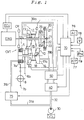
- Fig. 2 is a hydraulic circuit diagram of the control apparatus.
- Fig. 3 is a hydraulic circuit diagram of the control apparatus.
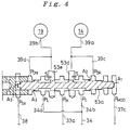
- Fig. 4 is an enlarged view of a shift valve used in the control apparatus.
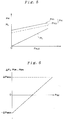
- Fig. 5 is a graph showing high and low pulley thrust control pressures set by the control apparatus.
- Fig. 6 is a graph showing the pressure difference between the pressures discharged by the shift valve.
- Fig. 7 is a graph showing starting clutch control pressures generated by the clutch control valve used in the control apparatus.
- a belt-type continuously variable transmission CVT having a control apparatus according to the present invention is schematically shown in Fig.1.
- This belt-type continuously variable transmission CVT comprises a metallic V-belt mechanism 10 disposed between an input shaft 1 and a countershaft 2, a planetary-gear forward-reverse selector mechanism 20 disposed between the input shaft 1 and the drive pulley 11 of the metallic V-belt mechanism 10, and a starting clutch 5 disposed between the countershaft 2 and a differential mechanism 8 as output member.
- the transmission CVT is suitable for use as a motor vehicle transmission.
- the input shaft 1 is connected with the output shaft of an engine ENG through a coupling mechanism CP.
- the power transmitted to the differential mechanism 8 drives the right and left wheels (not shown).
- the metallic V-belt mechanism 10 comprises a drive pulley 11 mounted on the input shaft 1, the driven pulley 16 mounted on the countershaft 2, and a metallic V-belt 15 trained around the drive and driven pulleys 11 and 16.
- the drive pulley 11 comprises an axially fixed pulley member 12 rotatably mounted on the input shaft 1, and a movable pulley member 13 axially slidable with respect to the fixed pulley member 12.
- the movable pulley member 13 has a cylinder chamber 14 defined axially laterally therein by a cylinder wall 12a coupled to the axially fixed pulley member 12.
- a hydraulic pressure, i.e., a pulley thrust pressure supplied into the cylinder chamber 14 through a hydraulic passage 39a generates a lateral thrust force for sliding the movable pulley member 13 axially toward the fixed pulley member 12.
- the driven pulley 16 comprises a fixed pulley member 17 fixedly mounted on the countershaft 2, and a movable pulley member 18 axially slidable with respect to the fixed pulley member 17.
- the movable pulley member 18 has a cylinder chamber 19 defined axially laterally therein by a cylinder wall 17a coupled to the fixed pulley member 17.
- a hydraulic pressure, i.e., a pulley thrust pressure, supplied into the cylinder chamber 19 through a hydraulic passage 39b generates a lateral thrust force for sliding the movable pulley member 18 axially toward the fixed pulley member 17.
- the planetary-gear forward-reverse selector mechanism 20 comprises a sun gear 21 coaxially coupled to the input shaft 1, a carrier 22 coupled to the axially fixed pulley member 12, a ring gear 23 which can be held against rotation by a reverse brake (a hydraulic actuator for reversing the drive) 27, and a forward clutch 25 capable of holding the sun gear 21 and the ring gear 23 together in rotation.
- a reverse brake a hydraulic actuator for reversing the drive
- a forward clutch 25 capable of holding the sun gear 21 and the ring gear 23 together in rotation.
- the forward clutch 25 When the forward clutch 25 is engaged, the sun gear 21, the planet gears on the carrier 22, and the ring gear 23 rotate in unison with the input shaft 1.
- the drive pulley 11 rotates in the same direction, i.e., forward direction, as the input shaft 1, thereby establishing the power transmission for forward drive.
- the starting clutch 5 controls transmission of power from the countershaft 2 to the output member.
- the starting clutch 5 When the starting clutch 5 is engaged and the engaging force thereof is controlled, the size of the torque transmitted from the countershaft 2 to the output member is controlled.
- power from the engine ENG is transmitted from the countershaft 2 through meshing gears 6a, 6b, 7a and 7b to the differential mechanism 8 at a speed ratio determined by the metallic V-belt mechanism 10. It is then divided and transmitted to the right and left wheels (not shown in the figure).
- torque transmission ratio is zero.
- power from the engine is not transmitted at all.
- the operation of the starting clutch 5 is manipulated by a clutch control valve 75 in response to control signals sent from a controller 70.
- the clutch control valve 75 regulates the hydraulic pressure (starting clutch control pressure Psc) supplied to the starting clutch 5 through passages 31a and 31b and thereby controls the operation thereof.
- the construction of the clutch control valve 75 will be described in detail later.
- the controller (judging means) 70 receives electric signals corresponding to the engine rotational speed Ne and the engine intake vacuum pressure PB from the engine control unit ECU which controls the operation of the engine ENG. In addition to these signals, it also receives a detection signal from the air-conditioner sensor 76 which detects whether the air-conditioner AC is operating or not, and a shift-range position signal from the shift-range detector 77 which detects the shift-range, basing on the position of the shift lever ATP. In corresponding to these signals, the controller 70 controls the above mentioned starting clutch 5 and a pulley thrust pressure valve unit 40 and a shift control valve unit 50, which will be described in the following.
- the controller 70 receives detection signals from the speed sensor 78 which detects the speed of the vehicle and the throttle sensor 79 which detects the degree of throttling. Basing on these detection signals from the speed sensor 78 and the throttle sensor 79, the controller 70 determines the vehicle's driving condition.
- the pulley thrust pressures supplied into the drive and driven cylinder chambers 14 and 19 are controlled by the pulley thrust pressure valve unit 40 and the shift control valve unit 50 in response to control signals received from the controller 70.
- the pulley thrust pressure valve unit 40 comprises a high pressure regulator valve 41, a low pressure regulator valve 43, a high/low pressure control valve 45, and a high pressure control valve 47.
- the shift control valve unit 50 comprises a shift control valve 51 and a shift valve 53. The constructions of these valves will be described in detail in the following description of the control apparatus.
- Oil from a hydraulic pump 30 is supplied through a hydraulic passage 32 to the above mentioned high pressure regulator valve 41. It is also supplied through a hydraulic passage 36 to a reducing valve 58 to generate a line pressure P MOD , which has a substantially constant pressure. The line pressure P MOD is then supplied to the above mentioned high/low pressure control valve 45, shift control valve 51, clutch control valve 75, and a manual valve 61 through passages 37a, 37b, 31a, and 31e.
- the high/low pressure control valve 45 includes a linear solenoid 45a. Control of the energizing current to the linear solenoid 45a enables control of the biassing force applied on the spool 45b. In correspondence with the biassing force applied on the spool, the high/low pressure control valve 45 converts or adjusts the line pressure P MOD supplied through the passage 37a to a control back-pressure P HLC . The control back-pressure P HLC produced is then supplied through a passage 35a into the right-end chamber 43b of the low pressure regulator valve 43, thereby pushing the spool 43a thereof to the left.
- the control back-pressure P HLC is also supplied through a passage 35b into the right-end chamber 47b of the high pressure control valve 47 and the first halfway chamber 47c next from the right end.
- the control back-pressure P HLC in the right-end chamber 47b pushes the spool 47a to the left, and the control back-pressure P HLC in the first halfway chamber 47c pushes the spool 47a to the right.
- the high pressure regulator valve 41 converts or adjusts the pressure of oil supplied through the passage 32 from the pump 30, to a high pulley thrust control pressure PH.
- the high pulley thrust control pressure PH generated here is then supplied to the shift valve 53 through a passage 33a and also to the low pressure regulator valve 43 through a passage 33b.
- the high pulley thrust control pressure PH is supplied to a passage 33c which branches from the passage 33a and connects to the left-end chamber 47d of the high pressure control valve 47.
- the second halfway chamber 47e of the high pressure control valve (shift pressure setting means) 47 is connected through a passage 66 to a reverse inhibitor valve 63.
- the spool 47a of the high pressure control valve 47 is positionally controlled by the control back-pressure P HLC received in the right-end chamber 47b and first halfway chamber 47c through the passage 35b and a second starting clutch control pressure Psc2, which will be described later, received in the second halfway chamber 47e through the passage 66.
- This positional control of the spool 47a enables the high pressure control valve 47 to adjust the high pulley thrust control pressure PH received through the passage 33c to a pressure which is supplied into the right-end chamber 41b of the high pressure regulator valve 41 as back pressure.
- the low pressure regulator valve 43 converts or adjusts the high pulley thrust control pressure PH supplied through the passage 33b to a low pulley thrust control pressure PL in correspondence with the control back-pressure P HLC .
- the low pulley thrust control pressure PL is then supplied to the shift valve 53 through a passage 34 and passages 34a and 34b, which are branched from the passage 34.
- Fig. 5 shows relations between the control back-pressure P HLC , which is produced by the high/low pressure control valve 45, and the high and low pulley thrust control pressures PH and PL, which are set by the high pressure regulator valve 41, high pressure control valve 47, and low pressure regulator valve 43.
- the high pulley thrust control pressure PH is switched between two pressures PH1 and PH 2 in correspondence with the judgment determined by the controller 70 on the driving condition of the vehicle. How this switching is carried out will be discussed later.
- the first pulley thrust control pressure PH1 shown by the solid line in the graph is selected while the vehicle is judged by the controller 70 as starting up, requiring control of the speed ratio, or as in kickdown, requiring rapid change of the speed ratio.
- the second pulley thrust control pressure PH2 ( ⁇ PH1) shown by the dotted line is selected while the vehicle is judge as in normal forward driving mode, requiring little control of the speed ratio (while only in forward drive as explained later).
- the low pulley thrust control pressure PL is a minimal pressure, when applied to the pulleys, which keeps the belt running without any slippage.
- the shift control valve 51 includes a linear solenoid 51a. Control of the energizing current through the linear solenoid 51a makes the biassing force applied to the spool 51b controllable. As such, the line pressure P MOD supplied through the passage 37b to the shift control valve 51 is adjusted to a shift control pressure P SV in correspondence with the biassing force. Then, the shift control pressure P SV is supplied into the left-end chamber 53b of the shift valve 53 through a passage 38, thereby pushing the spool 53a thereof to the right.
- the shift valve 53 controls the delivery of the high and low pulley thrust control pressures PH and PL selectively into the drive and driven cylinder chambers 14 and 19 through the passages 39a and 39b, corresponding to the position of the spool 53a.
- the left end surface (pressure-receiving area A3) of the spool 53a receives the shift control pressure P SV , which works to push the spool 53a to the right.
- the right end surface (pressure-receiving area A1) of the spool 53a receives the line pressure P MOD supplied through the passage 37c, which is branched from the passage 37b, whereby the spool 53a is pushed to the left.
- the right-side mediate surface (pressure-receiving area A2) of the spool 53a receives the inside pressure of the drive cylinder chamber 14, i.e, drive pulley thrust pressure P DR , through a drive pressure feedback passage 39c, which is branched from the passage 39a, whereby the spool 53a is pushed to the left.
- the left-side mediate surface (pressure-receiving area A2) of the spool 53a receives the inside pressure of the driven cylinder chamber 19, i.e, driven pulley thrust pressure P DN , through a driven pressure feedback passage 39d, which is branched from the passage 39b, whereby the spool 53a is pushed to the right.
- the spool 53a is shifted to the position where the force pushing the spool 53a to the left, i.e., P MOD x A1 + P DR x A2 , balances with the force pushing it to the right, i.e., P SV x A3 + P DN x A2 .
- the clutch control valve (clutch pressure control means) 75 has a linear solenoid 75a. Control of the energizing current to the linear solenoid 75a enables control of the biasing force working on the spool 75b. In correspondence with the biasing force so controlled, the line pressure P MOD supplied through the passage 31a is adjusted to generate the previously mentioned starting clutch control pressure P SC , which is discharged to the passage 31b and to a hydraulic passage 31c, which is branched from the passage 31b.
- the passage 31b is connected to the starting clutch 5, and the starting clutch control pressure P SC adjusts the engagement of the starting clutch 5.
- the passages 31c and 31d lead the starting clutch control pressure P SC into the left-end chamber 63b and the first halfway chamber 63c of the reverse inhibitor valve 63, respectively.
- the starting clutch control pressure P SC generated by the clutch control valve 75 is proportional to the energizing current I provided to the linear solenoid 75a from the controller 70.
- a categorization is made so as to assign three pressure ranges to the starting clutch control pressure P SC : a first starting clutch control pressure P SC 1 which ranges from zero to a maximal clutch torque control pressure P SC MAX for controlling the torque transmission ratio of the starting clutch 5; a second starting clutch control pressure P SC 2 which occupies the range greater than an actuation-initiating pressure PR (> P SC MAX) which is greater than the maximal clutch torque control pressure P SC MAX and initiates the actuation of the reverse inhibitor valve 63; and a third starting clutch control pressure P SC 3 which occupies the range greater than P SC MAX but smaller than the actuation-initiating pressure PR.
- the first starting clutch control pressure P SC 1 is used for controlling the engagement of the starting clutch 5, and the torque transmission ratio of the starting clutch 5 in engagement is controlled in correspondence with the magnitude of the first starting clutch control pressure P SC 1.
- the torque transmission ratio of the starting clutch 5 is set such that when the starting clutch 5 receives the first starting clutch control pressure P SC 1 equal to the maximal clutch torque control pressure P SC MAX, a maximum torque input on the input side is transmitted fully onto the output side without slippage in clutch engagement.
- the second starting clutch control pressure P SC 2 is used for fixing the transmission ratio of the starting clutch 5 at the maximum and for controlling the actuation of the reverse inhibitor valve 63.
- the third starting clutch control pressure P SC 3 is used only for fixing the transmission ratio of the starting clutch 5 at the maximum.
- the first starting clutch control pressure P SC 1 is applied while the condition of the vehicle is judged by the controller 70 as in starting mode (including forward start and reverse) or in kickdown mode.
- the second starting clutch control pressure P SC 2 is applied while the condition of the vehicle is judged as in normal forward driving mode
- the third starting clutch control pressure P SC 3 is applied while the vehicle is judged as in normal reverse driving mode.
- the manual valve 61 is connected to a shift lever provided at the driver's seat (not shown) with a cable.
- the shift lever is operated manually by the driver to one of the six positions P, R, N, D, S, and L, the spool 61a of the manual valve 61 is shifted correspondingly to one of the positions indicated in Fig. 3, which is showing the spool 61a at the N (neutral) position.
- the first halfway chamber 61b provided in the right portion of the manual valve 61 is connected to the forward clutch 25 through a passage 65, and the second halfway camber 61c provided in the left portion is connected to the reverse inhibitor valve 63 through a passage 67.
- This passage 67 is connected through the reverse inhibitor valve 63 to a passage 68 which is connected to the reverse brake 27.
- the line pressure P MOD is supplied into the right-end chamber 63d of the reverse inhibitor valve (open/close switching means) 63 through the passage 37c to push the spool 63a to the left.
- the first starting clutch control pressure P SC 1 or third starting clutch control pressure P SC 3 is supplied into the left-end chamber 63b of the reverse inhibitor valve 63 (i.e., the vehicle is in start up, kickdown, or normal reverse)
- the spool 63a is positioned at the left stroke end, and the passages 67 and 68 are connected to each other. Therefore, when the spool 61a of the manual valve 61 is at the R position, i.e., the passages 31e and 67 are connected with each other, the reverse brake 27 is actuated for engagement.
- the passage 66 connecting the reverse inhibitor valve 63 to the second halfway chamber 47e of the high pressure control valve 47 is connected to the drain.
- the high pulley thrust control pressure PH generated by the high pressure regulator valve 41 is switched from the first high pulley thrust control pressure PH1, which is generated to meet the need of frequent speed-ratio adjustment while the vehicle is starting, to the second high pulley thrust control pressure PH 2, which is generated at a pressure substantially smaller than the first high pulley thrust control pressure PH1, only to satisfy the need of less frequent speed-ratio adjustment while the vehicle is in normal forward driving mode.
- the load of the oil pump 30 is reduced correspondingly to this pressure reduction, whereby the fuel efficiency is improved as the engine runs with a less load.
- the vehicle is capable of driving while the starting clutch 5 and the forward clutch 25 or the reverse brake 27 are engaged.
- the spool 53a of the shift valve 53 positionally controlled through control of the shift control pressure P SV , the pressures supplied into the cylinder chambers 14 and 19 are controlled so as to control the speed ratio of the transmission.
- the clutch control pressure (second starting clutch control pressure P SC 2) is utilized as pressure for reducing the high pulley thrust control pressure.
- the pressure to be used for making a reduction in the high pulley trust control pressure is not limited to the clutch control pressure in the control apparatus of the present invention.
- the line pressure P MOD may be applied instead.
- the reverse inhibitor valve 63 is actuated by the second starting clutch control pressure P SC 2, which is generated by the clutch control valve 75, while the vehicle is in normal forward driving mode, without any consideration of the vehicle's speed.
- the clutch control valve 75 may be controlled to generate the second starting clutch control pressure P SC 2, for example, only when the speed of the vehicle, which is detected by the speed sensor 78, is above a predetermined value.
- control apparatus of the present invention is described as applied to a belt-type continuously variable transmission. However, it can be applied to other transmissions as well.
- a control apparatus For a transmission having a forward drive train, a reverse drive train and a starting clutch, a control apparatus comprises a clutch control valve for setting a clutch control pressure to control the engagement of the starting clutch and a reverse inhibitor valve for opening and closing a line to a reverse drive actuator.
- the clutch control pressure increases to a value above a predetermined value, the reverse inhibitor valve closes the line to the reverse drive actuator.
- a control apparatus For a transmission having drive and driven cylinders for controlling the speed ratio set by variable width drive and driven pulleys and a starting clutch for controlling power transmission; a control apparatus comprises a controller for judging whether or not a vehicle is in a predetermined normal forward driving mode (a driving condition which does not require a speed change or a rapid speed change), a clutch control valve for setting a clutch control pressure to control the engagement of the starting clutch, and a high pressure control valve for setting a speed-ratio changing pressure which is supplied to the drive and driven cylinders.
- a predetermined normal forward driving mode a driving condition which does not require a speed change or a rapid speed change
- a clutch control valve for setting a clutch control pressure to control the engagement of the starting clutch
- a high pressure control valve for setting a speed-ratio changing pressure which is supplied to the drive and driven cylinders.
- the high pressure control valve corresponding to the clutch control pressure sets the speed-ratio changing pressure to a pressure lower than the pressure set at while the vehicle is not in the predetermined normal forward driving mode.
Landscapes
- Engineering & Computer Science (AREA)
- General Engineering & Computer Science (AREA)
- Mechanical Engineering (AREA)
- Control Of Transmission Device (AREA)
Priority Applications (1)
| Application Number | Priority Date | Filing Date | Title |
|---|---|---|---|
| EP97115372A EP0813005B1 (fr) | 1995-01-26 | 1996-01-24 | Dispositif de commande pour transmission |
Applications Claiming Priority (4)
| Application Number | Priority Date | Filing Date | Title |
|---|---|---|---|
| JP2995195A JP3563804B2 (ja) | 1995-01-26 | 1995-01-26 | 変速機の制御装置 |
| JP29951/95 | 1995-01-26 | ||
| JP5049995A JP3614917B2 (ja) | 1995-02-15 | 1995-02-15 | 車両用変速機の制御装置 |
| JP50499/95 | 1995-02-15 |
Related Child Applications (1)
| Application Number | Title | Priority Date | Filing Date |
|---|---|---|---|
| EP97115372A Division EP0813005B1 (fr) | 1995-01-26 | 1996-01-24 | Dispositif de commande pour transmission |
Publications (3)
| Publication Number | Publication Date |
|---|---|
| EP0727598A2 true EP0727598A2 (fr) | 1996-08-21 |
| EP0727598A3 EP0727598A3 (fr) | 1996-10-16 |
| EP0727598B1 EP0727598B1 (fr) | 1998-08-12 |
Family
ID=26368207
Family Applications (2)
| Application Number | Title | Priority Date | Filing Date |
|---|---|---|---|
| EP96100996A Expired - Lifetime EP0727598B1 (fr) | 1995-01-26 | 1996-01-24 | Dispositif de commande pour transmission |
| EP97115372A Expired - Lifetime EP0813005B1 (fr) | 1995-01-26 | 1996-01-24 | Dispositif de commande pour transmission |
Family Applications After (1)
| Application Number | Title | Priority Date | Filing Date |
|---|---|---|---|
| EP97115372A Expired - Lifetime EP0813005B1 (fr) | 1995-01-26 | 1996-01-24 | Dispositif de commande pour transmission |
Country Status (3)
| Country | Link |
|---|---|
| US (1) | US5674150A (fr) |
| EP (2) | EP0727598B1 (fr) |
| DE (2) | DE69611355T2 (fr) |
Cited By (2)
| Publication number | Priority date | Publication date | Assignee | Title |
|---|---|---|---|---|
| EP1406032A2 (fr) * | 2002-09-12 | 2004-04-07 | JATCO Ltd | Dispositif de commande de pression hydraulique pour transmission continûment variable |
| WO2014170743A1 (fr) * | 2013-04-19 | 2014-10-23 | Toyota Jidosha Kabushiki Kaisha | Dispositif de commande hydraulique d'une transmission à variation continue du type à courroie |
Families Citing this family (12)
| Publication number | Priority date | Publication date | Assignee | Title |
|---|---|---|---|---|
| JP3524751B2 (ja) * | 1998-03-05 | 2004-05-10 | 本田技研工業株式会社 | 変速機の油圧制御装置 |
| JP2000018353A (ja) * | 1998-06-30 | 2000-01-18 | Isuzu Motors Ltd | 無段変速機 |
| JP3931033B2 (ja) * | 2000-12-01 | 2007-06-13 | 株式会社日立製作所 | 自動変速機の制御装置および制御方法 |
| US6840086B2 (en) * | 2003-03-06 | 2005-01-11 | Cincinnati Test Systems, Inc. | Method and apparatus for detecting leaks |
| US7128688B2 (en) * | 2003-04-25 | 2006-10-31 | Jatco Ltd | Hydraulic control for automatic transmission |
| US7048104B2 (en) * | 2003-09-12 | 2006-05-23 | Ford Global Technologies, Llc | Selective bypass of solenoid-controlled supply to friction elements of an automatic transmission |
| JP4457863B2 (ja) * | 2004-11-22 | 2010-04-28 | トヨタ自動車株式会社 | 車両用動力伝達機構の油圧制御装置 |
| JP4332518B2 (ja) * | 2005-10-06 | 2009-09-16 | 本田技研工業株式会社 | 動力伝達装置の制御装置 |
| JP2008045576A (ja) * | 2006-08-10 | 2008-02-28 | Yamaha Motor Co Ltd | 無段変速装置 |
| JP5218303B2 (ja) * | 2009-02-09 | 2013-06-26 | アイシン・エィ・ダブリュ株式会社 | 動力伝達装置 |
| JP2014137099A (ja) * | 2013-01-16 | 2014-07-28 | Jatco Ltd | 変速機の制御装置 |
| US10001199B2 (en) * | 2015-03-18 | 2018-06-19 | GM Global Technology Operations LLC | Continuously variable transmission and method for controlling the same |
Citations (6)
| Publication number | Priority date | Publication date | Assignee | Title |
|---|---|---|---|---|
| EP0231058A1 (fr) * | 1986-01-08 | 1987-08-05 | Fuji Jukogyo Kabushiki Kaisha | Système de commande pour transmission à variation de vitesse infinie pour des voitures |
| US4903551A (en) * | 1987-02-25 | 1990-02-27 | Mitsubishi Jidosha Kogyo Kabushiki Kaisha | Failsafe hydraulic control system for vehicle automatic transmission |
| EP0412718A2 (fr) * | 1989-08-09 | 1991-02-13 | Toyota Jidosha Kabushiki Kaisha | Dispositif de commande hydraulique pour le système de transmission d'un véhicule, y compris des soupapes empêchant le passage en marche arrière |
| US5088352A (en) * | 1988-05-06 | 1992-02-18 | Nissan Motor Co., Ltd. | System for controlling hydraulic fluid pressure for V-belt type automatic transmission |
| US5179874A (en) * | 1991-10-15 | 1993-01-19 | General Motors Corporation | Hydraulic control system for vehicular automatic transmissions |
| EP0498210B1 (fr) * | 1991-01-22 | 1995-06-28 | Honda Giken Kogyo Kabushiki Kaisha | Système de commande pour une transmission continue de vitesses |
Family Cites Families (11)
| Publication number | Priority date | Publication date | Assignee | Title |
|---|---|---|---|---|
| US4718308A (en) * | 1985-03-29 | 1988-01-12 | Borg-Warner Automotive, Inc. | Hydraulic control system for continuously variable transmission |
| JPH0676026B2 (ja) * | 1987-08-10 | 1994-09-28 | スズキ株式会社 | 連続可変変速機のクラッチ圧制御方法 |
| JPH0729571B2 (ja) * | 1987-08-10 | 1995-04-05 | スズキ株式会社 | 連続可変変速機のライン圧制御方法 |
| US5014839A (en) * | 1987-11-18 | 1991-05-14 | Honda Giken Kogyo Kabushiki Kaisha | Drive train of a wheeled vehicle and method for controlling the same |
| JPH0721311B2 (ja) * | 1988-11-30 | 1995-03-08 | スズキ株式会社 | 連続可変変速機のベルトレシオ制御装置 |
| US5052980A (en) * | 1989-02-13 | 1991-10-01 | Toyota Jidosha Kabushiki Kaisha | Hydraulic control apparatus for vehicle power transmitting system having continuously variable transmission |
| US5007512A (en) * | 1989-08-31 | 1991-04-16 | Borg-Warner Automotive, Inc. | Technique for clutch control in continuously variable transmission systems |
| JP2844363B2 (ja) * | 1989-09-30 | 1999-01-06 | スズキ株式会社 | 連続可変変速機制御方法 |
| JP2863932B2 (ja) * | 1989-09-30 | 1999-03-03 | スズキ株式会社 | 連続可変変速機制御装置 |
| US5062050A (en) * | 1989-10-17 | 1991-10-29 | Borg-Warner Automotive, Inc. | Continuously variable transmission line pressure control |
| US5170868A (en) * | 1990-10-31 | 1992-12-15 | Suzuki Motor Corporation | Automatic starting clutch control method |
-
1996
- 1996-01-24 DE DE69611355T patent/DE69611355T2/de not_active Expired - Fee Related
- 1996-01-24 DE DE69600503T patent/DE69600503T2/de not_active Expired - Fee Related
- 1996-01-24 EP EP96100996A patent/EP0727598B1/fr not_active Expired - Lifetime
- 1996-01-24 EP EP97115372A patent/EP0813005B1/fr not_active Expired - Lifetime
- 1996-01-26 US US08/592,776 patent/US5674150A/en not_active Expired - Fee Related
Patent Citations (6)
| Publication number | Priority date | Publication date | Assignee | Title |
|---|---|---|---|---|
| EP0231058A1 (fr) * | 1986-01-08 | 1987-08-05 | Fuji Jukogyo Kabushiki Kaisha | Système de commande pour transmission à variation de vitesse infinie pour des voitures |
| US4903551A (en) * | 1987-02-25 | 1990-02-27 | Mitsubishi Jidosha Kogyo Kabushiki Kaisha | Failsafe hydraulic control system for vehicle automatic transmission |
| US5088352A (en) * | 1988-05-06 | 1992-02-18 | Nissan Motor Co., Ltd. | System for controlling hydraulic fluid pressure for V-belt type automatic transmission |
| EP0412718A2 (fr) * | 1989-08-09 | 1991-02-13 | Toyota Jidosha Kabushiki Kaisha | Dispositif de commande hydraulique pour le système de transmission d'un véhicule, y compris des soupapes empêchant le passage en marche arrière |
| EP0498210B1 (fr) * | 1991-01-22 | 1995-06-28 | Honda Giken Kogyo Kabushiki Kaisha | Système de commande pour une transmission continue de vitesses |
| US5179874A (en) * | 1991-10-15 | 1993-01-19 | General Motors Corporation | Hydraulic control system for vehicular automatic transmissions |
Cited By (6)
| Publication number | Priority date | Publication date | Assignee | Title |
|---|---|---|---|---|
| EP1406032A2 (fr) * | 2002-09-12 | 2004-04-07 | JATCO Ltd | Dispositif de commande de pression hydraulique pour transmission continûment variable |
| EP1406032A3 (fr) * | 2002-09-12 | 2006-04-19 | JATCO Ltd | Dispositif de commande de pression hydraulique pour transmission continûment variable |
| US7211013B2 (en) | 2002-09-12 | 2007-05-01 | Jatco Ltd | Hydraulic control apparatus for V-belt type continuously variable transmission |
| WO2014170743A1 (fr) * | 2013-04-19 | 2014-10-23 | Toyota Jidosha Kabushiki Kaisha | Dispositif de commande hydraulique d'une transmission à variation continue du type à courroie |
| JP2014211206A (ja) * | 2013-04-19 | 2014-11-13 | トヨタ自動車株式会社 | ベルト式無段変速機の油圧制御装置 |
| US10054221B2 (en) | 2013-04-19 | 2018-08-21 | Toyota Jidosha Kabushiki Kaisha | Hydraulic control device of belt-type continuously variable transmission |
Also Published As
| Publication number | Publication date |
|---|---|
| EP0813005B1 (fr) | 2000-12-27 |
| US5674150A (en) | 1997-10-07 |
| EP0813005A2 (fr) | 1997-12-17 |
| DE69600503T2 (de) | 1998-12-17 |
| EP0727598B1 (fr) | 1998-08-12 |
| DE69600503D1 (de) | 1998-09-17 |
| EP0727598A3 (fr) | 1996-10-16 |
| DE69611355T2 (de) | 2001-04-26 |
| DE69611355D1 (de) | 2001-02-01 |
| EP0813005A3 (fr) | 1998-05-27 |
Similar Documents
| Publication | Publication Date | Title |
|---|---|---|
| US5690576A (en) | Continuously variable transmission with control of switching between forward and reverse | |
| EP1138981A2 (fr) | Variateur continu de vitesse | |
| US5662547A (en) | Continuously variable transmission | |
| EP0813005B1 (fr) | Dispositif de commande pour transmission | |
| US20060111207A1 (en) | Hydraulic control system for vehicular power transmitting mechanism | |
| JP2587774B2 (ja) | ベルト式無段変速機の制御装置 | |
| JP3524751B2 (ja) | 変速機の油圧制御装置 | |
| US6146308A (en) | Creep torque control of infinitely variable transmission | |
| EP0982512B1 (fr) | Commande d'embrayage hydraulique | |
| EP0779453A2 (fr) | Variateur continu de vitesse | |
| EP0724096B1 (fr) | Dispositif de commande de pression axiale de poulies pour transmission à variation continue à courroie | |
| US5569114A (en) | Pulley thrust pressure control apparatus for belt-type continuously variable transmission | |
| JP3469182B2 (ja) | 車両用無段変速機の制御装置 | |
| KR100564195B1 (ko) | 벨트식 무단 변속기의 변속 유압 제어 장치 | |
| KR20010019805A (ko) | 자동차용 무단 변속기의 유압 제어 시스템 | |
| EP0762018B1 (fr) | Commande hydraulique pour une transmission de véhicule à variation continue | |
| JP3614917B2 (ja) | 車両用変速機の制御装置 | |
| JPH1054458A (ja) | 自動変速機用油圧制御装置 | |
| JP3424505B2 (ja) | 無段変速機の変速制御装置 | |
| JP3563804B2 (ja) | 変速機の制御装置 | |
| JP3498423B2 (ja) | 無段変速機 | |
| JPH09166215A (ja) | 無段変速機 | |
| JPH08326860A (ja) | 無段変速機 | |
| JP2005042888A (ja) | 車両用無段変速機の油圧制御装置 | |
| JP3009502B2 (ja) | 車両の動力伝達装置 |
Legal Events
| Date | Code | Title | Description |
|---|---|---|---|
| PUAI | Public reference made under article 153(3) epc to a published international application that has entered the european phase |
Free format text: ORIGINAL CODE: 0009012 |
|
| AK | Designated contracting states |
Kind code of ref document: A2 Designated state(s): DE GB |
|
| PUAL | Search report despatched |
Free format text: ORIGINAL CODE: 0009013 |
|
| AK | Designated contracting states |
Kind code of ref document: A3 Designated state(s): DE GB |
|
| 17P | Request for examination filed |
Effective date: 19961029 |
|
| 17Q | First examination report despatched |
Effective date: 19961204 |
|
| GRAG | Despatch of communication of intention to grant |
Free format text: ORIGINAL CODE: EPIDOS AGRA |
|
| GRAG | Despatch of communication of intention to grant |
Free format text: ORIGINAL CODE: EPIDOS AGRA |
|
| GRAH | Despatch of communication of intention to grant a patent |
Free format text: ORIGINAL CODE: EPIDOS IGRA |
|
| GRAH | Despatch of communication of intention to grant a patent |
Free format text: ORIGINAL CODE: EPIDOS IGRA |
|
| GRAA | (expected) grant |
Free format text: ORIGINAL CODE: 0009210 |
|
| AK | Designated contracting states |
Kind code of ref document: B1 Designated state(s): DE GB |
|
| DX | Miscellaneous (deleted) | ||
| REF | Corresponds to: |
Ref document number: 69600503 Country of ref document: DE Date of ref document: 19980917 |
|
| PLBE | No opposition filed within time limit |
Free format text: ORIGINAL CODE: 0009261 |
|
| STAA | Information on the status of an ep patent application or granted ep patent |
Free format text: STATUS: NO OPPOSITION FILED WITHIN TIME LIMIT |
|
| 26N | No opposition filed | ||
| REG | Reference to a national code |
Ref country code: GB Ref legal event code: IF02 |
|
| PGFP | Annual fee paid to national office [announced via postgrant information from national office to epo] |
Ref country code: GB Payment date: 20030122 Year of fee payment: 8 |
|
| PGFP | Annual fee paid to national office [announced via postgrant information from national office to epo] |
Ref country code: DE Payment date: 20030206 Year of fee payment: 8 |
|
| PG25 | Lapsed in a contracting state [announced via postgrant information from national office to epo] |
Ref country code: GB Free format text: LAPSE BECAUSE OF NON-PAYMENT OF DUE FEES Effective date: 20040124 |
|
| PG25 | Lapsed in a contracting state [announced via postgrant information from national office to epo] |
Ref country code: DE Free format text: LAPSE BECAUSE OF NON-PAYMENT OF DUE FEES Effective date: 20040803 |
|
| GBPC | Gb: european patent ceased through non-payment of renewal fee |
Effective date: 20040124 |