EP0727362A1 - Presentation and packaging device for sporting articles like table tennis bats - Google Patents
Presentation and packaging device for sporting articles like table tennis bats Download PDFInfo
- Publication number
- EP0727362A1 EP0727362A1 EP96400282A EP96400282A EP0727362A1 EP 0727362 A1 EP0727362 A1 EP 0727362A1 EP 96400282 A EP96400282 A EP 96400282A EP 96400282 A EP96400282 A EP 96400282A EP 0727362 A1 EP0727362 A1 EP 0727362A1
- Authority
- EP
- European Patent Office
- Prior art keywords
- panel
- panels
- legs
- article
- tabs
- Prior art date
- Legal status (The legal status is an assumption and is not a legal conclusion. Google has not performed a legal analysis and makes no representation as to the accuracy of the status listed.)
- Withdrawn
Links
Images

Classifications
-
- B—PERFORMING OPERATIONS; TRANSPORTING
- B65—CONVEYING; PACKING; STORING; HANDLING THIN OR FILAMENTARY MATERIAL
- B65D—CONTAINERS FOR STORAGE OR TRANSPORT OF ARTICLES OR MATERIALS, e.g. BAGS, BARRELS, BOTTLES, BOXES, CANS, CARTONS, CRATES, DRUMS, JARS, TANKS, HOPPERS, FORWARDING CONTAINERS; ACCESSORIES, CLOSURES, OR FITTINGS THEREFOR; PACKAGING ELEMENTS; PACKAGES
- B65D73/00—Packages comprising articles attached to cards, sheets or webs
- B65D73/0078—Packages comprising articles attached to cards, sheets or webs the articles being retained or enclosed in a folded-over or doubled card
Definitions
- the present invention relates to a device for the support, presentation and packaging of sporting articles with handle, of the table tennis racket type.
- the sale or presentation for sale of sporting goods is more and more frequently carried out in self-service type sales outlets, where the articles are displayed on shelves, shelves, hooks, suspensions or any other similar system.
- the removability must allow the customer to take the article to look at it and possibly replace it without difficulty.
- the arrangement of the articles must also be carried out so as to allow maximum exposure of each article.
- the packaging must have a minimum size and a reduced manufacturing cost.
- known devices have in common the fact that they present faults on the one hand to be made bottom-up since they are destroyed and then thrown away by the customer once the purchase has been made and on the other hand not to allow the customer to remove the item from the packaging to try it at the point of sale.
- the present invention aims to remedy these drawbacks and proposes a device intended to allow the support, the presentation, the packaging of a sporting article such as a table tennis racket, allowing the attachment to a pin, to visualize, touch and take said article, having a reduced bulk and allowing to take out the article and try it, and finally having an additional function and utility that can be used by the user once the item has been purchased.
- the device for the support, the presentation and the packaging of sporting articles with handle such as rackets of table tennis, of the type comprising means able to cooperate with a body of 'hooking (such as a rod), is characterized in that it is made of a rigid or semi-rigid material and has two substantially flat and parallel panels connected, at least on a part of the periphery, by a strip or section of tape.
- the device has an opening, preferably at the top.
- the device comprises at least one hole or light provided on one face for attachment, preferably in the upper part.
- the latter comprises at least one lumen on one of the faces, and preferably two, one for the handle. , the other for the active part of the racket.
- the device has two notches facing each other and of similar shape and size.
- the notches are U-shaped or with a rounded bottom and preferably with an axis inclined relative to the longitudinal axis of the device.
- the device is produced by folding from a single flat sheet whose folded edges are assembled by gluing, welding, stapling, heat sealing or the like.
- it has, in plan view, a substantially triangular or trapezoidal lower part and a substantially quadrangular upper part.
- edges of the panels have curved and / or rounded shapes.
- the device can be made of plastic, metal, cardboard or wood.
- Figure 1 shows a plan view of a flat sheet of rigid or semi-rigid material.
- said material is made of cardboard, but it is understood that any other similar material is likely to be suitable, such as for example light wood, plastic or metal.
- the single sheet comprises a first panel 1 and a second panel 2 connected by a central flank 3 of junction, along at least a part of two sides respectively 4 and 5 of the latter. Sides 4 and 5 form fold lines.
- the first and second panels each have an upper part inscribed substantially in a rectangle, respectively 6 and 7, and a lower part substantially triangular or trapezoidal, the point being directed on the side opposite to the upper part and bearing the respective references 8 and 9.
- the first and second panels 1 and 2 have, with respect to a longitudinal axis not shown (vertical in FIG. 1), passing through the middle of the joining flank 3, a substantially symmetrical shape, with the exception of the elements mentioned above. after.
- the second panel 2 comprises a rectangular strip 10 and elongated in the longitudinal direction of said panel, and attached to the base 11 of the trapezoid formed by the second lower part 9 which constitutes the junction line between the panel 2 and the strip 10.
- the line 11 is a fold line.
- the strip 10 comprises five successive segments 12 to 16, linked in pairs by a fold line 11a to 11d.
- the first panel 1 comprises three substantially rectangular tabs 17, 18 and 19, respectively connected to the panel 1 by a fold line 20, 21 and 22, along a part of the sides of the panel 1.
- the first tab 17 is arranged parallel to the longitudinal axis of the panel, along the side 20 of the quadrangular part 6 of said panel.
- the second and third legs 18 and 19 are arranged along the oblique sides 21 and 22 of the trapezoid formed by the second lower part 8 of said first panel 1.
- Each tab 17, 18 and 19 comprises a longitudinal fold line, substantially median 23, 24 and 25, delimiting, for each tab, two parallel strips 17A, 17B; 18A, 18B; 19A, 19B.
- the distal bands 17A, 18A and 19A are bevelled on their transverse edges and thus form a trapezoid.
- the first panel 1 comprises in its trapezoidal lower part 8, an oblong opening 32, of substantially trapezoidal shape, the large base of which is situated on the lower side 33 of the panel 1.
- FIGS. 2 and 3 the production and shaping of the device of the invention, from the sheet of material shown flat in FIG. 1.
- the first panel 1 is folded over the panel 2 and parallel to it, using the longitudinal fold lines 4 and 5, common to the central junction flank 3.
- the joining flank 3 is arranged perpendicularly to the latter, and the distal bands 17A, 18A and 19A bear against the panel 2, where they are then fixed by any suitable means , such as for example gluing, in the case of cardboard material.
- the device then takes the form shown in perspective in FIG. 3, after the lower strip 10 has been folded and assembled by successive folds along the fold lines 11, 11a, 11b, 11c and 11d, so that two successive segments of the strip 10 are perpendicular to each other. More particularly, the strip 10 is folded on itself in a "spiral".
- the first segment 12 is perpendicular to the panels 1 and 2; the segment 13 is disposed against the panel 1; the segment 14 is perpendicular to the panels and penetrates inside the oblong opening 32; the fold line joining the segments 13 and 14 is parallel and against the large base of the trapezoid formed by light 32; the segment 15 is disposed against the panel 2; and the last segment 16 is perpendicular to the panels and pressed against the underside of the first segment 12.
- Securing means by stapling or gluing for example, are provided for fixing together the first and last segments 11 and 16 of the strip 10.
- the latter constitutes a means of strengthening and stiffening the lower part of the device.
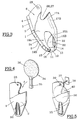
- FIG 4 there is shown a perspective view of the device of the invention once completed, and a table tennis racket 34 ready to be arranged inside the device.
- the racket 4 can be wrapped in a transparent plastic film (not shown).
- the device defines a closed volume, with the exception of an upper opening through which the racket is introduced (arrow f), parallel to the panels 1 and 2, the handle 35 downwards and the active part 36 upwards.
- FIG. 5 shows the device inside which the racket 34 is placed and suspended from a display comprising a horizontal rod 37, integral with a base 38, itself fixed to a wall, piece of furniture or the like, for the purpose of presentation of the racket.
- the rod 37 is introduced into the circular slots 28 and 29, until the end 39 of the rod protrudes from the first panel constituting the front panel.
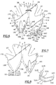
- FIGS. 6 and 7 an alternative embodiment of the device according to the invention, deployed flat, respectively showing an internal view and an external view of the device.
- interior view is meant a view showing the faces arranged opposite in the assembled position of the device.
- FIGS. 6 and 7 differs in particular from a different embodiment of the fixing lugs to the small base of the trapezoid formed by the lower part of the device and by lugs in which the fixing method is different.
- FIG. 6 corresponds to the representation of FIG. 1, with the alternative embodiments.
- the first panel 1 has a notch 32 ', substantially equivalent to the lumen 32 of the device of Figure 1.
- the notch 1 is open downwards, on the side opposite to the fixing holes 28 and 29 of the device.
- the first panel 1 has three rectangular tabs 17C, 18C and 19C, respectively connected to said panel by fold lines 20, 21 and 22 respectively, along a part of the sides of said panel. Along each fold line is provided a recessed portion of elongated and narrow shape, over a portion of the length of the fold lines 20, 21 and 22. These recessed elongated portions bear the references 47 (for tab 17C), 48 (for 18C leg) and 49 (for 19C leg).
- the ends of the legs 18C and 19C are each extended by a tongue 18D and 19D respectively, of quadrangular shape and having a length substantially or very substantially less than the length 18C and 19C legs.
- the tongues 18D and 19D are connected to the legs 18C and 19C by a fold line, respectively 50 and 51.
- the second panel 2 also comprises, symmetrically with respect to the panel 1, a lug 17D, a lug 18E and a lug 19E, the latter being respectively arranged symmetrically with respect to the lugs 17C, 18C and 19C of the panel 1.
- the legs 17D, 18E and 19E are connected to panel 2 by fold lines 20A, 21A and 22A respectively.
- a fixing assembly On the panel 2 is provided a fixing assembly described below.
- a tab 12 connected to the panel 2 by a fold line 11, and also connected by a succession of fold lines, to a first transverse tongue 52 and a second tongue 53, arranged parallel to the first and slightly spaced from the latter, being connected by a bridge of material 54 and corresponding fold lines.
- the transverse tabs 52 and 53 thus comprise a central part 52A and 53A, and two lateral tabs 52B, 52C and 53B and 53C, respectively; they thus form a kind of H offset by 90 °.
- the tabs 17C, 18C, 19C, 19E, 18E, 17D are folded along the corresponding fold lines, so that said tabs are arranged perpendicular to the plane of the corresponding panel.
- tabs 18D and 19D are in turn folded substantially transversely to the legs to which they are attached; said tabs 18D and 19D are then found substantially superimposed on each other. They are then fixed by a point of adhesive in the usual way.
- the lower fixing tabs and tabs, arranged at the base of the panel 2, are folded in the following manner, with reference to FIG. 6 and to FIG. 8, showing a partial perspective view of the tabs once folded, at the exclusion of legs 18E and 19E, and of the panel, for a better understanding of the drawing.
- the lower tab 12 is first folded perpendicular to the panel 2, along the fold line 11, and the transverse tabs 52 and 53 are also folded in the transverse direction (perpendicular to the longitudinal axis of the device), along the lines of folding referenced, as shown in Figure 6, respectively 56, 57, 58 and 59.
- the folding is carried out so that the planes of two tabs or tabs separated by a folding line are perpendicular to each other.
- transverse legs 52 and 53 are folded towards the central part of the legs 52 and 53, along longitudinal fold lines .
- legs 52B and 53B, and 52A and 53A, and 52C and 53C are respectively parallel in pairs and delimit a sort of open channel in the upper part (facing the observer, the sheet 2 being placed flat) .
- the panel 1 By performing a tilting (rotation) movement of the first panel 1 on the panel 2, as symbolized by the arrow in FIG. 6, and by folding along the fold lines 4 and 5 of the central strip 3, the panel 1 is folded over the panel 2. In doing so, the tabs 47A, 48A and 49A are introduced, lugs 17D, 18E and 19E, in lights 47, 48, 49, legs 17C, 18C and 19D. Glue dots 60 are provided on the legs so as to allow the association of the legs 17C and 17D, 18C and 18E, and 19C and 19E.
- the channel delimited by the legs and tongues of the device in the lower part is able to thus receive the lower parts 18C and 19C, and the tongues 18D and 19D, forming a sort of V with a horizontal base.
- the tongues 52 and 53 constitute a means of reinforcement and stiffening of the lower part of the device.
- the different tabs, tongues and the like are fixed by gluing, for example, with gluing products known in themselves.
- the material constituting the device can be cardboard, with a density of between 100 and 500 g / m 2 , and preferably of the order of 400 g / m 2 .
- the handle 35 of the racket is visible and protrudes relative to the front face of the panel 1.
- the handle 35 is not only visible but capable of being touched by the customer (in the no plastic film wrapping the racket).
- the notch 26 provided in the first panel allows viewing and touching a part 40 of the active part 36 of the racket.
- the device is easy to make using a sheet of flat material.
- the assembly and fixing of the panels parallel to each other are carried out by gluing, stapling, welding, thermoforming, etc., depending on the material used.
- the joining lines between the panels, strips, segments are formed by pre-folding lines, lines of weakness, bridges of material or the like.
- the device may be used after purchase by the customer as packaging for transporting the racket on the one hand and / or as a stiffening element inside a bag or any other flexible container. intended to contain the racket.
Abstract
Description
La présente invention concerne un dispositif pour le support, la présentation et l'emballage d'articles de sport à manche, du type raquette de tennis de table.The present invention relates to a device for the support, presentation and packaging of sporting articles with handle, of the table tennis racket type.
La vente ou présentation à la vente d'articles de sport est de plus en plus fréquemment réalisée dans des lieux de vente du type libre-service, où les articles sont présentés sur des rayons, étagères, crochets, suspensions ou tout autre système analogue.The sale or presentation for sale of sporting goods is more and more frequently carried out in self-service type sales outlets, where the articles are displayed on shelves, shelves, hooks, suspensions or any other similar system.
Ceci soulève plusieurs difficultés.This raises several difficulties.
Il faut tout d'abord fixer les articles de manière stable mais également amovible pour permettre au client de prendre lesdits articles, une fois son choix effectué.It is first of all necessary to fix the articles in a stable but also removable manner to allow the customer to take said articles, once his choice made.
De plus, l'amovibilité doit permettre au client de prendre l'article pour le regarder et éventuellement le replacer sans difficulté.In addition, the removability must allow the customer to take the article to look at it and possibly replace it without difficulty.
La disposition des articles doit être par ailleurs réalisée de manière à permettre une exposition maximale de chaque article.The arrangement of the articles must also be carried out so as to allow maximum exposure of each article.
En outre, le client souhaite pouvoir, non seulement voir l'article, mais également le toucher et l'essayer. Ceci est d'autant plus important pour des articles du type raquette de tennis de table.In addition, the customer wants to be able to not only see the article, but also to touch and try it. This is all the more important for articles of the table tennis racket type.
Enfin, l'emballage doit présenter un encombrement minimal et un coût de fabrication réduit.Finally, the packaging must have a minimum size and a reduced manufacturing cost.
Or, les dispositifs connus souffrent de nombreux défauts et, en toute hypothèse, ne permettent pas de concilier les contraintes contradictoires mentionnées ci-dessus.However, the known devices suffer from numerous faults and, in any event, do not make it possible to reconcile the contradictory constraints mentioned above.
En effet, les dispositifs connus sous forme de coquille plastique (blister), s'ils permettent l'examen visuel de l'article, n'en autorisent pas l'accès, ni le toucher ; ils sont de plus relativement onéreux.Indeed, the devices known in the form of a plastic shell (blister), if they allow visual examination of the article, do not allow access to it or touch it; they are also relatively expensive.
On connaît également des emballages faisant appel à un film rétractable. Ce type d'emballage ne permet pas l'accrochage, sauf à l'associer à un panneau en carton qui conduit à augmenter le coût de l'emballage alors constitué de deux matériaux différents. De plus, il est fragile et présente les mêmes défauts que le blister, en ce qui concerne l'accès et le toucher de l'article par le client.There are also known packages using a shrink film. This type of packaging does not allow hanging, except to associate it with a cardboard panel which leads to increasing the cost of the packaging then made of two different materials. In addition, it is fragile and has the same defects as the blister, with regard to access and touch of the article by the customer.
On a proposé des dispositifs sous forme de boite en carton. Ces derniers ne permettent pas d'examiner visuellement le produit et encore moins de le toucher.Devices have been proposed in the form of a cardboard box. These do not allow to visually examine the product and even less to touch it.
De plus, les dispositifs connus ont en commun de présenter les défauts d'une part d'être réalisés à fond perdu puisqu'ils sont détruits et jetés ensuite par le clients une fois l'achat effectué et d'autre part de ne pas permettre au client de sortir l'article de l'emballage pour l'essayer dans le lieu de vente.In addition, known devices have in common the fact that they present faults on the one hand to be made bottom-up since they are destroyed and then thrown away by the customer once the purchase has been made and on the other hand not to allow the customer to remove the item from the packaging to try it at the point of sale.
La présente invention vise à remédier à ces inconvénients et propose un dispositif destiné à permettre le support, la présentation, l'emballage d'un article de sport tel que raquette de tennis de table, permettant l'accrochage à un broche, de visualiser, toucher et prendre ledit article, présentant un encombrement réduit et permettant de sortir l'article et essayer ce dernier, et enfin présentant une fonction et une utilité additionnelle susceptible d'être mises à profit par l'utilisateur une fois l'article acheté.The present invention aims to remedy these drawbacks and proposes a device intended to allow the support, the presentation, the packaging of a sporting article such as a table tennis racket, allowing the attachment to a pin, to visualize, touch and take said article, having a reduced bulk and allowing to take out the article and try it, and finally having an additional function and utility that can be used by the user once the item has been purchased.
A cette fin, selon l'invention, le dispositif pour le support, la présentation et l'emballage d'articles de sport à manche, tels que des raquettes de tennis de table, du type comprenant des moyens aptes à coopérer avec un organe d'accrochage (tel qu'une tige), est caractérisé en ce qu'il est réalisé en un matériau rigide ou semi-rigide et présente deux panneaux sensiblement plans et parallèles reliés, au moins sur une partie de pourtour, par une bande ou tronçon de bande.To this end, according to the invention, the device for the support, the presentation and the packaging of sporting articles with handle, such as rackets of table tennis, of the type comprising means able to cooperate with a body of 'hooking (such as a rod), is characterized in that it is made of a rigid or semi-rigid material and has two substantially flat and parallel panels connected, at least on a part of the periphery, by a strip or section of tape.
Afin de permettre l'enlèvement de l'article, le dispositif comporte une ouverture, de préférence en partie supérieure.In order to allow the article to be removed, the device has an opening, preferably at the top.
Le dispositif comporte au moins un trou ou lumière prévu sur une face en vue de l'accrochage, de préférence en partie supérieure.The device comprises at least one hole or light provided on one face for attachment, preferably in the upper part.
En vue de permettre le toucher de l'article sans enlever celui-ci du dispositif de support et d'emballage, celui-ci comporte au moins une lumière sur l'une des faces, et de préférence deux, l'une pour le manche, l'autre pour la partie active de la raquette.In order to allow the article to be touched without removing it from the support and packaging device, the latter comprises at least one lumen on one of the faces, and preferably two, one for the handle. , the other for the active part of the racket.
Afin que l'utilisateur puisse saisir l'article et l'enlever du dispositif, celui-ci comporte deux échancrures en regard l'une de l'autre et de forme et dimension similaires.So that the user can grasp the item and remove it from the device, the device has two notches facing each other and of similar shape and size.
Avantageusement, les échancrures sont en forme de U ou de à fond arrondis et de préférence d'axe incliné par rapport à l'axe longitudinal du dispositif.Advantageously, the notches are U-shaped or with a rounded bottom and preferably with an axis inclined relative to the longitudinal axis of the device.
Dans le but notamment de simplifier la réalisation et réduire les coûts, le dispositif est réalisé par pliage à partir d'une feuille plane unique dont les bords rabattus sont assemblés par collage, soudage, agrafage, thermosoudure ou similaire.With the particular aim of simplifying production and reducing costs, the device is produced by folding from a single flat sheet whose folded edges are assembled by gluing, welding, stapling, heat sealing or the like.
Suivant une forme de réalisation particulière, il présente, en vue en plan, une partie inférieure sensiblement triangulaire ou trapézoïdale et une partie supérieure sensiblement quadrangulaire.According to a particular embodiment, it has, in plan view, a substantially triangular or trapezoidal lower part and a substantially quadrangular upper part.
Pour des raisons de sécurité et pour faciliter la manipulation, les bords des panneaux présentent des formes courbes et/ou arrondies.For safety reasons and to facilitate handling, the edges of the panels have curved and / or rounded shapes.
Le dispositif peut être réalisé en plastique, métal, carton ou bois.The device can be made of plastic, metal, cardboard or wood.
L'invention sera bien comprise à la lumière de la description qui suit se rapportant à un exemple illustratif mais non limitatif de l'invention, en référence au dessin annexé dans lequel :
- la figure 1 montre une vue en plan d'une feuille de matériau, déployée à plat, destinée à réaliser le dispositif de l'invention ;
- la figure 2 montre le dispositif de la figure 1 où les pattes latérales sont rabattues ;
- la figure 3 montre une vue en perspective du dispositif une fois assemblé ;
- la figure 4 montre de dispositif de l'invention en perspective et une raquette de tennis de table ;
- la figure 5 montre une vue du dispositif contenant une raquette de tennis de table et suspendu à un crochet ;
- les figures 6 et 7 montrent une variante de réalisation déployée à plat, respectivement en vue de face intérieure et de face extérieure ; et
- la figure 8 est une vue partielle de détail des languettes et pattes de fixation à la base du dispositif, en position repliée.
- Figure 1 shows a plan view of a sheet of material, deployed flat, for making the device of the invention;
- Figure 2 shows the device of Figure 1 where the side tabs are folded down;
- Figure 3 shows a perspective view of the device once assembled;
- Figure 4 shows a device of the invention in perspective and a table tennis racket;
- Figure 5 shows a view of the device containing a table tennis racket and hanging from a hook;
- Figures 6 and 7 show an alternative embodiment deployed flat, respectively in view of inner face and outer face; and
- Figure 8 is a partial detail view of the tabs and lugs for fixing to the base of the device, in the folded position.
La figure 1 montre une vue en plan d'une feuille à plat de matériau rigide ou semi-rigide. Dans le cadre de l'exemple de réalisation décrit, ledit matériau est constitué de carton, mais il est bien entendu que tout autre matériau similaire est susceptible de convenir, tel que par exemple bois léger, plastique ou métal.Figure 1 shows a plan view of a flat sheet of rigid or semi-rigid material. In the context of the embodiment described, said material is made of cardboard, but it is understood that any other similar material is likely to be suitable, such as for example light wood, plastic or metal.
La feuille unique comporte un premier panneau 1 et un second panneau 2 reliés par un flanc central 3 de jonction, le long d'au moins une partie de deux côtés respectivement 4 et 5 de ces derniers. Les côtés 4 et 5 forment des lignes de pliage. Les premier et second panneau présentent chacun une partie supérieure inscrite sensiblement dans un rectangle, respectivement 6 et 7, et une partie inférieure sensiblement triangulaire ou trapézoïdale, la pointe étant dirigée du côté opposé à la partie supérieure et portant les références respectives 8 et 9.The single sheet comprises a
Les premier et second panneaux 1 et 2 présentent, par rapport à un axe longitudinal non représenté (vertical sur la figure 1), passant par le milieu du flanc de jonction 3, une forme sensiblement symétrique, à l'exception des éléments mentionnés ci-après.The first and
Le second panneau 2 comporte une bande 10 rectangulaire et allongée dans la direction longitudinale dudit panneau, et rattachée à la base 11 du trapèze formé par la seconde partie inférieure 9 qui constitue la ligne de jonction entre le panneau 2 et la bande 10. La ligne 11 est une ligne de pliage. La bande 10 comporte cinq segments successifs 12 à 16, reliés deux à deux par un ligne de pliage 11a à 11d.The
Le premier panneau 1 comporte trois pattes sensiblement rectangulaires 17, 18 et 19, respectivement reliées au panneau 1 par une ligne de pliage 20, 21 et 22, le long d'une partie des côtés du panneau 1.The
La première patte 17 est disposée parallèlement à l'axe longitudinal du panneau, le long du côté 20 de la partie quadrangulaire 6 dudit panneau. Les seconde et troisième pattes 18 et 19 sont disposées le long des côtés obliques 21 et 22 du trapèze formé par la seconde partie inférieure 8 dudit premier panneau 1.The
Chaque patte 17, 18 et 19 comporte une ligne de pliage longitudinale, sensiblement médiane 23, 24 et 25, délimitant, pour chaque patte, deux bandes parallèles 17A, 17B ; 18A, 18B ; 19A, 19B. Les bandes distales 17A, 18A et 19A sont biseautées sur leurs bords transversaux et forment ainsi un trapèze.Each
Les parties supérieures 6 et 7 des panneaux 1 et 2 comportent chacune, de façon symétrique :
- une échancrure respectivement 26, 27 en forme générale de U ou de V à fond arrondi, et d'axe incliné par rapport à l'axe longitudinal de chaque
panneau 1 et 2 . - une lumière circulaire 28, 29 à proximité du bord supérieur transversal 30, 31 ; lesdits bords supérieurs présentant une forme courbe à concavité tournée vers les panneaux.
- a
notch panel - a
circular lumen upper edge
Le premier panneau 1 comporte en sa partie inférieure trapézoïdale 8, une lumière oblongue 32, de forme sensiblement trapézoïdale dont la grande base est située du côté inférieur 33 du panneau 1.The
On décrit maintenant, en regard des figure 2 et 3, la réalisation et mise en forme du dispositif de l'invention, à partir de la feuille de matériau représentée à plat sur la figure 1.We will now describe, with reference to FIGS. 2 and 3, the production and shaping of the device of the invention, from the sheet of material shown flat in FIG. 1.
Dans un premier temps, les pattes 17, 18 et 19 sont pliéés à 90° le long des lignes de pliage (23, 20) ; (24, 21) ; et (25, 22) de manière que les bandes de chaque patte forme, avec le panneau 1, une sorte de U, vu dans un plan transversal au plan dudit panneau. On aboutit ainsi à la configuration de la figure 2.Initially, the
Ensuite, le premier panneau 1 est rabattu sur le panneau 2 et parallèlement à celui-ci, à l'aide des lignes de pliage longitudinales 4 et 5, communes au flanc central de jonction 3.Then, the
Une fois les panneaux 1 et 2 disposés en regard et en superposition, le flanc de jonction 3 est disposé perpendiculairement à ces derniers, et les bandes distales 17A, 18A et 19A portent contre le panneau 2, où elles sont ensuite fixées par tout moyen approprié, tel que par exemple collage, dans le cas de matériau en carton.Once the
Le dispositif prend alors la forme montrée en perspective sur la figure 3, après que la bande inférieure 10 ait été pliée et assemblée par pliages successifs le long des lignes de pliage 11, 11a, 11b, 11c et 11d, de manière que deux segments successifs de la bande 10 soient perpendiculaires l'un à l'autre. Plus particulièrement, la bande 10 est pliée sur elle-même en "colimaçon".The device then takes the form shown in perspective in FIG. 3, after the
Le premier segment 12 est perpendiculaire aux panneaux 1 et 2 ; le segment 13 est disposé contre le panneau 1 ; le segment 14 est perpendiculaire aux panneaux et pénètre à l'intérieur de la lumière oblongue 32 ; la ligne de pliage joignant les segments 13 et 14 est parallèle et contre la grande base du trapèze formé par lumière 32 ; le segment 15 est disposé contre le panneau 2 ; et le dernier segment 16 est perpendiculaire aux panneaux et plaqué contre la face inférieure du premier segment 12.The
Des moyens de solidarisation par agrafage ou collage par exemple, sont prévus pour fixer ensemble les premier et dernier segments 11 et 16 de la bande 10. Cette dernière constitue un moyen de renforcement et de rigidification de la partie basse du dispositif.Securing means by stapling or gluing for example, are provided for fixing together the first and
En référence à la figure 4, on a représenté une vue en perspective du dispositif de l'invention une fois terminé, et une raquette 34 de tennis de table prête à être disposée à l'intérieur du dispositif. La raquette 4 peut être enveloppée dans un film plastique transparent (non représenté).Referring to Figure 4, there is shown a perspective view of the device of the invention once completed, and a
Le dispositif délimite un volume fermé, à l'exception d'une ouverture supérieure par où est introduite la raquette (flèche f), parallèlement aux panneaux 1 et 2, le manche 35 vers le bas et la partie active 36 vers le haut.The device defines a closed volume, with the exception of an upper opening through which the racket is introduced (arrow f), parallel to the
La figure 5 montre le dispositif à l'intérieur duquel est disposée la raquette 34 et suspendu à un présentoir comprenant une tige horizontale 37, solidaire d'un socle 38, lui-même fixé à un mur, meuble ou analogue, en vue de la présentation de la raquette.FIG. 5 shows the device inside which the
La tige 37 est introduite dans les lumières circulaires 28 et 29, jusqu'à ce que l'extrémité 39 de la tige dépasse du premier panneau constituant le panneau frontal.The
On a représenté aux figures 6 et 7 une variante de réalisation du dispositif selon l'invention, déployé à plat, montrant respectivement une vue intérieure et une vue extérieure du dispositif. Les éléments communs du dispositif des figures 6 et 7 d'une part et du dispositif montré sur les autres figures 1 à 5 d'autre part, et qui sont similaires, équivalents ou identiques, portent les mêmes références. On entend par vue intérieure une vue montrant les faces disposées en regard en position assemblée du dispositif.There is shown in Figures 6 and 7 an alternative embodiment of the device according to the invention, deployed flat, respectively showing an internal view and an external view of the device. The common elements of the device of FIGS. 6 and 7 on the one hand and of the device shown in the other FIGS. 1 to 5 on the other hand, and which are similar, equivalent or identical, bear the same references. By interior view is meant a view showing the faces arranged opposite in the assembled position of the device.
La variante de réalisation des figures 6 et 7 se différencie notamment pas une forme de réalisation différente des pattes de fixation à la petite base du trapèze formée par la partie inférieure du dispositif et par des pattes dont le mode de fixation est différent. A noter que la figure 6 correspond à la représentation de la figure 1, aux variantes de forme de réalisation près.The variant embodiment of FIGS. 6 and 7 differs in particular from a different embodiment of the fixing lugs to the small base of the trapezoid formed by the lower part of the device and by lugs in which the fixing method is different. Note that FIG. 6 corresponds to the representation of FIG. 1, with the alternative embodiments.
En référence à la figure 6, le premier panneau 1 comporte une échancrure 32', sensiblement équivalente à la lumière 32 du dispositif de la figure 1. L'échancrure 1 est ouverte vers le bas, du côté opposé aux trous de fixation 28 et 29 du dispositif.Referring to Figure 6, the
Le premier panneau 1 comporte trois pattes rectangulaires 17C, 18C et 19C, respectivement reliées audit panneau par des lignes de pliage respectivement 20, 21 et 22, le long d'une partie des côtés dudit panneau. Le long de chaque ligne de pliage est prévue une partie évidée de forme allongée et étroite, sur une partie de la longueur des lignes de pliage 20, 21 et 22. Ces parties évidées allongées portent les références 47 (pour la patte 17C), 48 (pour la patte 18C) et 49 (pour la patte 19C).The
L'extrémité des pattes 18C et 19C (disposées le long des côtés obliques de la partie inférieure 8 trapézoïdale), 5 sont prolongées chacune par une languette respectivement 18D et 19D, de forme quadrangulaire et présentant une longueur sensiblement ou très sensiblement inférieure à la longueur des pattes 18C et 19C. Les languettes 18D et 19D sont reliées aux pattes 18C et 19C par une ligne de pliage, respectivement 50 et 51.The ends of the
Le second panneau 2 comporte également, de manière symétrique par rapport au panneau 1, une patte 17D, une patte 18E et une patte 19E, ces dernières étant respectivement disposées de manière symétrique par rapport aux pattes 17C, 18C et 19C du panneau 1. Les pattes 17D, 18E et 19E sont reliées au panneau 2 par des lignes de pliage respectivement 20A, 21A et 22A.The
Ces mêmes pattes comportent, le long de leur bord longitudinal libre, une languette de forme allongée et étroite, et sur une partie de la longueur desdites pattes. Ces languettes, portant les références respectives 47A, 48A et 49A, sont susceptibles d'être associées et de pénétrer dans les lumière 47, 48 et 49 du panneau 1 et décrites ci-dessus.These same legs have, along their free longitudinal edge, a tongue of elongated and narrow shape, and over a part of the length of said legs. These tabs, bearing the
Sur le panneau 2 est prévu un ensemble de fixation décrit ci-après. A la base du panneau 2 (vers la petite base du trapèze formé par la partie inférieure 9) est prévue une patte 12 reliée au panneau 2 par une ligne de pliage 11, et également reliée par une succession de lignes de pliage, à une première languette transversale 52 et une seconde languette 53, disposée parallèlement à la première et légèrement espacée de cette dernière, en étant reliée par un pont de matière 54 et de lignes de pliage correspondantes. Les pattes transversales 52 et 53 comportent ainsi une partie centrale 52A et 53A, et deux languettes latérales 52B, 52C et 53B et 53C, respectivement ; elles forment ainsi une sorte de H décalé de 90°.On the
On retrouve sur la figure 7 les mêmes éléments, le dispositif étant montré du côté de la face extérieure.We find in Figure 7 the same elements, the device being shown on the side of the outer face.
Le montage du dispositif des figures 6 et 7 est le suivant.The assembly of the device of Figures 6 and 7 is as follows.
En partant de la disposition à plat de la figure 6, les pattes 17C, 18C, 19C, 19E, 18E, 17D sont repliées selon les lignes de pliage correspondantes, de manière que lesdites pattes soient disposées perpendiculairement au plan du panneau correspondant.Starting from the flat arrangement of Figure 6, the
Ensuite, les languettes 18D et 19D sont à leur tour pliées sensiblement transversalement aux pattes auxquelles elles sont rattachées ; lesdites languettes 18D et 19D se retrouvent alors sensiblement superposées l'une à l'autre. Elles sont alors fixées par un point de colle de manière usuelle.Then, the
Les pattes et languettes de fixation inférieures, disposées à la base du panneau 2, sont pliées de la manière suivante, en référence à la figure 6 et à la figure 8, montrant une vue partielle en perspective des languettes une fois repliées, à l'exclusion des pattes 18E et 19E, et du panneau, pour une meilleure compréhension du dessin.The lower fixing tabs and tabs, arranged at the base of the
La patte inférieure 12 est d'abord pliée perpendiculairement au panneau 2, selon la ligne de pliage 11, et les pattes transversales 52 et 53 sont également pliées dans le sens transversal (perpendiculaire à l'axe longitudinal du dispositif), selon les lignes de pliage référencées, comme montré sur la figure 6, respectivement 56, 57, 58 et 59. Les pliages sont effectués de manière que les plans de deux pattes ou languettes séparées par une ligne de pliage soient perpendiculaires l'une à l'autre.The
Egalement, les couples de languettes latérales 52B et 52C, d'une part, et 53B et 53C, d'autre part, des pattes transversales 52 et 53 sont repliées vers la partie centrale des pattes 52 et 53, selon des lignes de pliage longitudinales.Also, the pairs of
On aboutit ainsi, à la position représentée à la figure 8 qui ne montre que les languettes 52 et 53, et les pattes associées.This leads to the position shown in Figure 8 which shows only the
On comprend que les pattes 52B et 53B, et 52A et 53A, et 52C et 53C, sont respectivement parallèles deux à deux et délimitent une sorte de canal ouvert en partie supérieure (face à l'observateur, la feuille 2 étant posée à plat).It is understood that the
En effectuant un mouvement de basculement (rotation) du premier panneau 1 sur le panneau 2, comme symbolisé par la flèche sur la figure 6, et en pliant le long des lignes de pliage 4 et 5 de la bande centrale 3, on rabat le panneau 1 sur le panneau 2. Ce faisant, on introduit les languettes 47A, 48A et 49A, des pattes 17D, 18E et 19E, dans les lumières 47, 48, 49, des pattes 17C, 18C et 19D. Des points de colle 60 sont prévus sur les pattes de manière à permettre l'association des pattes 17C et 17D, 18C et 18E, et 19C et 19E.By performing a tilting (rotation) movement of the
Le canal délimité par les pattes et languettes du dispositif en partie inférieure (figure 8) est apte à recevoir ainsi les parties inférieures 18C et 19C, et les languettes 18D et 19D, formant une sorte de V à base horizontale.The channel delimited by the legs and tongues of the device in the lower part (FIG. 8) is able to thus receive the
Les languettes 52 et 53 constituent un moyen de renforcement et de rigidification de la partie inférieure du dispositif.The
Les différentes pattes, languettes et analogues sont fixées par collage par exemple, avec des produits de collage connus en eux-mêmes.The different tabs, tongues and the like are fixed by gluing, for example, with gluing products known in themselves.
A titre d'exemple, le matériau constitutif du dispositif peut être du carton, de densité comprise entre 100 et 500 g/m2, et de préférence de l'ordre de 400g/m2.By way of example, the material constituting the device can be cardboard, with a density of between 100 and 500 g / m 2 , and preferably of the order of 400 g / m 2 .
En référence à la figure 5, le manche 35 de la raquette est visible et fait saillie par rapport à la face frontale du panneau 1. Ainsi, le manche 35 est non seulement visible mais susceptible d'être touché par le client (en l'absence de film plastique enveloppant la raquette).With reference to FIG. 5, the
De plus, l'échancrure 26 prévue dans le premier panneau, permet de visualiser et toucher une partie 40 de la partie active 36 de la raquette.In addition, the
La présence de deux échancrures 26 et 27 en regard, permettent au client de saisir la raquette par pincement, pour la sortir du dispositif de support et de présentation, en vue d'essayer la raquette et de se faire une idée de sa tenue en main par exemple.The presence of two
Il est à noter que ces maniements sont rendus possibles sans altération, modification ou endommagement du support/présentoir de l'invention.It should be noted that these operations are made possible without alteration, modification or damage to the support / display unit of the invention.
Le dispositif est facile à réaliser à l'aide d'une feuille de matériau à plat. L'assemblage et fixation des panneaux parallèlement l'un à l'autre sont réalisés par collage, agrafage, soudage, thermoformage, etc., en fonction du matériau utilisé. De même, les lignes de jonction entre les panneaux, bandes, segments, sont constituées par des lignes de pré-pliage, lignes de faiblesse, ponts de matière ou analogue.The device is easy to make using a sheet of flat material. The assembly and fixing of the panels parallel to each other are carried out by gluing, stapling, welding, thermoforming, etc., depending on the material used. Likewise, the joining lines between the panels, strips, segments, are formed by pre-folding lines, lines of weakness, bridges of material or the like.
Enfin, le dispositif est susceptible d'être utilisé après achat par le client à titre d'emballage pour le transport de la raquette d'une part et/ou comme élément de rigidification à l'intérieur d'un sac ou tout autre conteneur souple destiné à contenir la raquette.Finally, the device may be used after purchase by the customer as packaging for transporting the racket on the one hand and / or as a stiffening element inside a bag or any other flexible container. intended to contain the racket.
Claims (14)
Applications Claiming Priority (2)
| Application Number | Priority Date | Filing Date | Title |
|---|---|---|---|
| FR9501830A FR2730707B1 (en) | 1995-02-17 | 1995-02-17 | DEVICE FOR THE PRESENTATION AND PACKAGING OF SPORTS ITEMS SUCH AS TABLE TENNIS RACKETS |
| FR9501830 | 1995-02-17 |
Publications (1)
| Publication Number | Publication Date |
|---|---|
| EP0727362A1 true EP0727362A1 (en) | 1996-08-21 |
Family
ID=9476241
Family Applications (1)
| Application Number | Title | Priority Date | Filing Date |
|---|---|---|---|
| EP96400282A Withdrawn EP0727362A1 (en) | 1995-02-17 | 1996-02-12 | Presentation and packaging device for sporting articles like table tennis bats |
Country Status (2)
| Country | Link |
|---|---|
| EP (1) | EP0727362A1 (en) |
| FR (1) | FR2730707B1 (en) |
Cited By (1)
| Publication number | Priority date | Publication date | Assignee | Title |
|---|---|---|---|---|
| USD738957S1 (en) | 2011-06-29 | 2015-09-15 | Target Brands, Inc. | Transaction product |
Citations (4)
| Publication number | Priority date | Publication date | Assignee | Title |
|---|---|---|---|---|
| US2075624A (en) * | 1936-02-13 | 1937-03-30 | Contalner Corp Of America | Container |
| US2384974A (en) * | 1943-06-08 | 1945-09-18 | Marie F Smith | Receptacle |
| US2956676A (en) * | 1958-03-13 | 1960-10-18 | Pioneer Folding Box Inc | Punch board displays for paint brushes and the like |
| FR2611667A1 (en) * | 1987-02-24 | 1988-09-09 | Amco | Package for racquet, a table tennis bat in particular |
-
1995
- 1995-02-17 FR FR9501830A patent/FR2730707B1/en not_active Expired - Fee Related
-
1996
- 1996-02-12 EP EP96400282A patent/EP0727362A1/en not_active Withdrawn
Patent Citations (4)
| Publication number | Priority date | Publication date | Assignee | Title |
|---|---|---|---|---|
| US2075624A (en) * | 1936-02-13 | 1937-03-30 | Contalner Corp Of America | Container |
| US2384974A (en) * | 1943-06-08 | 1945-09-18 | Marie F Smith | Receptacle |
| US2956676A (en) * | 1958-03-13 | 1960-10-18 | Pioneer Folding Box Inc | Punch board displays for paint brushes and the like |
| FR2611667A1 (en) * | 1987-02-24 | 1988-09-09 | Amco | Package for racquet, a table tennis bat in particular |
Cited By (1)
| Publication number | Priority date | Publication date | Assignee | Title |
|---|---|---|---|---|
| USD738957S1 (en) | 2011-06-29 | 2015-09-15 | Target Brands, Inc. | Transaction product |
Also Published As
| Publication number | Publication date |
|---|---|
| FR2730707B1 (en) | 1997-04-04 |
| FR2730707A1 (en) | 1996-08-23 |
Similar Documents
| Publication | Publication Date | Title |
|---|---|---|
| FR1450241A (en) | Improvements to packaging boxes | |
| EP1329391A1 (en) | Display package | |
| FR2899566A1 (en) | Item or article packaging box for self service mega store, has front walls, of base and cover, articulated by using flap with break line, where cover is separated from base by traction from break line of rear wall of base | |
| FR2571949A1 (en) | Folding display case having an automatic unfolding capability | |
| EP0727362A1 (en) | Presentation and packaging device for sporting articles like table tennis bats | |
| EP0720955A1 (en) | Packaging and display container, in particular for bicycles | |
| FR2629432A1 (en) | ||
| EP1092651B1 (en) | Package for conditioning and presenting articles grouped in batches | |
| FR2660626A1 (en) | DEVICE FOR SUSPENSION OF ARTICLES TO A DISPLAY AND APPLICATIONS OF SAID DEVICE FOR SUPPORTING PACKAGING AND / OR PACKAGED ARTICLE. | |
| FR2550764A1 (en) | Packaging carton for containers such as bottles | |
| EP0297013B1 (en) | Foldable container with incurred faces capable of being stored flat and erected by simple pressure | |
| FR2708572A1 (en) | Package for item, particularly for sales display | |
| FR2798648A1 (en) | Cardboard package especially for medication has hinged pouch to contain information sheet | |
| FR2550518A1 (en) | Sales package | |
| EP0277859B1 (en) | Display carton for glasses and similar articles | |
| BE1025258B1 (en) | BOX FOR PACKAGING PRODUCTS | |
| FR2848197A1 (en) | Garment e.g. dress, package, has slot leading to opening in plane perpendicular to length of slot, and unit maintaining dress in containers interior on longitudinal shift of dress, where slot holds column of bent metallic hanger | |
| FR2551422A1 (en) | Battery-holder tray | |
| FR2559740A1 (en) | Tamper-proof display package forming a case which can be reused for various objects | |
| WO1995033653A1 (en) | Foldable box with curved sides and method of manufacture | |
| EP1736414A1 (en) | Assembly for transportation and presentation of at least one object, packaging procedure using such an assembly and procedure of opening | |
| FR2562513A1 (en) | Display container-package for glasses and similar items | |
| FR2727384A1 (en) | Container used for transporting, storage and display of poultry | |
| FR2794106A1 (en) | Packaging for poultry has cardboard strip panel placed longitudinally around bird | |
| FR2692558A1 (en) | Container with variable capacity for self service - uses mono-material construction with base including hanging tag and products securely located in between flaps |
Legal Events
| Date | Code | Title | Description |
|---|---|---|---|
| PUAI | Public reference made under article 153(3) epc to a published international application that has entered the european phase |
Free format text: ORIGINAL CODE: 0009012 |
|
| AK | Designated contracting states |
Kind code of ref document: A1 Designated state(s): BE DE ES FR GB IT LU NL PT |
|
| STAA | Information on the status of an ep patent application or granted ep patent |
Free format text: STATUS: THE APPLICATION IS DEEMED TO BE WITHDRAWN |
|
| 18D | Application deemed to be withdrawn |
Effective date: 19970222 |