EP0727292B1 - verfahren zur herstellung von hartholzbodenstreifen - Google Patents
verfahren zur herstellung von hartholzbodenstreifen Download PDFInfo
- Publication number
- EP0727292B1 EP0727292B1 EP96300282A EP96300282A EP0727292B1 EP 0727292 B1 EP0727292 B1 EP 0727292B1 EP 96300282 A EP96300282 A EP 96300282A EP 96300282 A EP96300282 A EP 96300282A EP 0727292 B1 EP0727292 B1 EP 0727292B1
- Authority
- EP
- European Patent Office
- Prior art keywords
- blank
- cut
- saw blades
- strip
- thickness
- Prior art date
- Legal status (The legal status is an assumption and is not a legal conclusion. Google has not performed a legal analysis and makes no representation as to the accuracy of the status listed.)
- Expired - Lifetime
Links
Images


Classifications
-
- B—PERFORMING OPERATIONS; TRANSPORTING
- B23—MACHINE TOOLS; METAL-WORKING NOT OTHERWISE PROVIDED FOR
- B23D—PLANING; SLOTTING; SHEARING; BROACHING; SAWING; FILING; SCRAPING; LIKE OPERATIONS FOR WORKING METAL BY REMOVING MATERIAL, NOT OTHERWISE PROVIDED FOR
- B23D45/00—Sawing machines or sawing devices with circular saw blades or with friction saw discs
- B23D45/10—Sawing machines or sawing devices with circular saw blades or with friction saw discs with a plurality of circular saw blades
- B23D45/105—Sawing machines or sawing devices with circular saw blades or with friction saw discs with a plurality of circular saw blades operating within the same plane
-
- B—PERFORMING OPERATIONS; TRANSPORTING
- B27—WORKING OR PRESERVING WOOD OR SIMILAR MATERIAL; NAILING OR STAPLING MACHINES IN GENERAL
- B27B—SAWS FOR WOOD OR SIMILAR MATERIAL; COMPONENTS OR ACCESSORIES THEREFOR
- B27B31/00—Arrangements for conveying, loading, turning, adjusting, or discharging the log or timber, specially designed for saw mills or sawing machines
- B27B31/08—Discharging equipment
-
- B—PERFORMING OPERATIONS; TRANSPORTING
- B27—WORKING OR PRESERVING WOOD OR SIMILAR MATERIAL; NAILING OR STAPLING MACHINES IN GENERAL
- B27G—ACCESSORY MACHINES OR APPARATUS FOR WORKING WOOD OR SIMILAR MATERIALS; TOOLS FOR WORKING WOOD OR SIMILAR MATERIALS; SAFETY DEVICES FOR WOOD WORKING MACHINES OR TOOLS
- B27G19/00—Safety guards or devices specially adapted for wood saws; Auxiliary devices facilitating proper operation of wood saws
- B27G19/08—Accessories for keeping open the saw kerf, e.g. riving knives or wedge plates
-
- B—PERFORMING OPERATIONS; TRANSPORTING
- B27—WORKING OR PRESERVING WOOD OR SIMILAR MATERIAL; NAILING OR STAPLING MACHINES IN GENERAL
- B27M—WORKING OF WOOD NOT PROVIDED FOR IN SUBCLASSES B27B - B27L; MANUFACTURE OF SPECIFIC WOODEN ARTICLES
- B27M3/00—Manufacture or reconditioning of specific semi-finished or finished articles
- B27M3/04—Manufacture or reconditioning of specific semi-finished or finished articles of flooring elements, e.g. parqueting blocks
-
- B—PERFORMING OPERATIONS; TRANSPORTING
- B28—WORKING CEMENT, CLAY, OR STONE
- B28D—WORKING STONE OR STONE-LIKE MATERIALS
- B28D1/00—Working stone or stone-like materials, e.g. brick, concrete or glass, not provided for elsewhere; Machines, devices, tools therefor
- B28D1/02—Working stone or stone-like materials, e.g. brick, concrete or glass, not provided for elsewhere; Machines, devices, tools therefor by sawing
- B28D1/04—Working stone or stone-like materials, e.g. brick, concrete or glass, not provided for elsewhere; Machines, devices, tools therefor by sawing with circular or cylindrical saw-blades or saw-discs
- B28D1/046—Sawing in a plane parallel to the work table
-
- Y—GENERAL TAGGING OF NEW TECHNOLOGICAL DEVELOPMENTS; GENERAL TAGGING OF CROSS-SECTIONAL TECHNOLOGIES SPANNING OVER SEVERAL SECTIONS OF THE IPC; TECHNICAL SUBJECTS COVERED BY FORMER USPC CROSS-REFERENCE ART COLLECTIONS [XRACs] AND DIGESTS
- Y10—TECHNICAL SUBJECTS COVERED BY FORMER USPC
- Y10T—TECHNICAL SUBJECTS COVERED BY FORMER US CLASSIFICATION
- Y10T428/00—Stock material or miscellaneous articles
- Y10T428/16—Two dimensionally sectional layer
- Y10T428/163—Next to unitary web or sheet of equal or greater extent
-
- Y—GENERAL TAGGING OF NEW TECHNOLOGICAL DEVELOPMENTS; GENERAL TAGGING OF CROSS-SECTIONAL TECHNOLOGIES SPANNING OVER SEVERAL SECTIONS OF THE IPC; TECHNICAL SUBJECTS COVERED BY FORMER USPC CROSS-REFERENCE ART COLLECTIONS [XRACs] AND DIGESTS
- Y10—TECHNICAL SUBJECTS COVERED BY FORMER USPC
- Y10T—TECHNICAL SUBJECTS COVERED BY FORMER US CLASSIFICATION
- Y10T428/00—Stock material or miscellaneous articles
- Y10T428/31504—Composite [nonstructural laminate]
- Y10T428/31971—Of carbohydrate
- Y10T428/31989—Of wood
Definitions
- This invention relates to a low profile hardwood flooring product method of manufacture.
- the end product resulting from the processes described below is a hardwood flooring strip having a nominal thickness of 8mm (5/16") and a nominal width of either 57mm (2 1/4) or 83mm (3 1/4").
- the strips are intended to be sold as a prefinished "nail-down" product. After installation, the product is indistinguishable from a conventional 19mm (3/4") thick hardwood flooring product of like width.
- the lower profile offers a number of substantial advantages. First, because almost twice the floor coverage can be achieved with the same amount of wood, very substantial savings in wood resources are possible.
- the low profile When installed as a aftermarket product to replace an existing floor, the low profile permits installation over a floor where conventional carpet and padding was previously installed without the need to raise door bottoms or provide transitions between the new hardwood floor and adjacent flooring of other types. This results in very substantial labor savings.
- Prior art methods of producing low profile wood flooring include simply planing down full-thickness boards with a substantial amount of resulting waste sawdust and very little actual saving in the wood used.
- the prior art also includes cutting over-thickness boards, typically with a thickness of approximately 32mm (1.25"), widthwise with a bandsaw.
- a bandsaw-cut board has a very uneven cut surface which cannot be used even on the hidden surface of the board without substantial further planing.
- Both prior art processes are relatively slow, produce a relatively low quality product, and create bottlenecks in automated production lines which require high processing speeds.
- Prior art processes have not provided a means of precisely controlling the positioning of the blank from which the strip of flooring is produced, where the wood is sufficiently thin at the beginning of the process to provide significant savings in material and waste.
- the present method uses the same full thickness stock material used to produce conventional full thickness flooring, thus permitting the same production line to be used up to the splitting process itself.
- U.S. 1,584,796 provides a resawing machine which includes twin circular saws adapted to cut lumber as it leaves the planing mill at any desired angle to a horizontal plane.
- counterrotating saw blades are used to "split" hardwood flooring material into very high quality low profile flooring strips at rates which are compatible with processing speeds of the other manufacturing processes, such as planing. This is accomplished by very precisely controlling the position of the wood blank before, during and after the splitting process.
- the result is a prefinished floor manufactured to extremely close tolerances, and with square edges which fit flush in the same manner as "sand-in-place" flooring.
- a method of producing a hardwood flooring product comprising the steps of processing a strip of raw wood into a blank having a predetermined thickness and width, and top and bottom surfaces defining parallel planes relative to each other and splitting the blank along the width from one side to the other to form two low profile flooring strips having the same width as the blank and a thickness less than one-half the thickness of the blank; the splitting step comprising the steps of providing first and second circular saw blades mounted on spaced-apart vertical axes for rotation in a single plane intermediate and parallel to the planes of the top and bottom surfaces of the blank and positioning the blank on conveying means upstream from said saw blades with the plane of rotation of said saw blades intermediate and parallel to the planes of the top and bottom surfaces of said blank for movement of the blank from an upstream position to a downstream position relative to said saw blades and moving the blank downstream into the plane of rotation of said saw blades during rotation of the saw blades thereby horizontally splitting the blank to form first and second low-profile flooring strips; increasing the width of the
- Interlocking members such as mating tongue and groove members, may be molded into first and second longitudinally-extending side edges of the flooring strips for securing together flooring strips placed side-to-side to form a floor.
- An embodiment of the method according to the invention may include the step of counterrotating the saw blades in a direction wherein both first and second saw blades cut into the wood in the upstream direction against the downstream direction of travel of the blank.
- the step of providing first and second saw blades include the step of positioning the first saw blade upstream from the second saw blade whereby the first saw blade begins its cut before the second saw blade begins its cut.
- the first saw blade may be positioned upstream from the second saw blade and therefore begins its cut before the second saw blade begins its cut, and wherein both the first and second saw blades are positioned relative to the path of travel of the blank to cut into the blank more than one-half the distance of the width of the blank.
- the cutting thickness of the first and second saw blades, and thus the cutting waste of the splitting process may be more than 10 percent and less than 20 percent of the thickness of the blank.
- the step of increasing the width of the cut in the blank may comprise the step of introducing a plate into the area of the cut in the blank, the plate having a thickness sufficient to increase the width of the cut and thereby spread apart the blank on opposite sides of the cut.
- the step of increasing the width of the cut in the blank may comprise the step of introducing first and second opposed plates into the area of the cut in the blank from opposite sides of the blank, each of the first and second plates having a thickness sufficient to increase the width of the cut and thereby spread apart the blank on opposite sides of the cut.
- the blank may be less than 25.4mm (one inch) in thickness as the method steps begin, and the finished flooring strip in its finished form has a nominal thickness of 8mm (5/16 inch).
- the rate of feed of the blank into the saw blades of the splitter may be at a rate of not less than 1 metre per second (200 feet per minute).
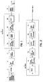
- Figures 1-6 a wood flooring strip manufacturing process which includes a method of splitting a blank into a low profile wooden flooring strip according to the present invention is illustrated in Figures 1-6.
- Figures 1-4 set out the process steps in flow-diagram form, while Figures 5 and 6 illustrate in broad form the apparatus which splits the wood blanks into low profile flooring strips.
- Figures 7, 8 and 9 illustrate a completed flooring strip and assembled floor.
- the following description of the preferred embodiment and best mode for practicing the method of the invention uses numbered steps for identification which correlate to the sequentially-numbered boxes of Figures 1-4.
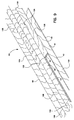
- FIG. 5 a simplified illustration of the splitting process described in Step 5, above, is illustrated.
- a blank 10 from the knot sawing step (Step 4) is planed bottom and top by a pair of rotating planing heads 11 and 12.
- Each of the planing heads 11 and 12 carry a set of radially, outwardly extending planing blades 11A and 12A, respectively. See Step 5A, above.
- planing heads 14 and 15 carry a set of radially, outwardly extending planing blades 14A and 15A, respectively. See Step 5B, above.
- the various conventional pressure and feed rollers which control the movement of the blank 10 have been removed from Figure 5 for clarity.
- the blank 10 is planed bottom and top a second time, this time by planing heads 17 and 18.
- Each of the planing heads 14 and 15 carry a set of radially, outwardly extending planing blades 17A and 18A, respectively. See Step 5C, above.
- the blank 10 is held in position by conventional pressure shoes, beds and fences so that the finish tolerances are very precise, even though the blanks 10 are moving between 250 and 300 feet per minute.
- the blank 10 is then "split" by circular splitter blades 20 and 21 along a horizontal plane into two identical strips, each 8.4mm (.332") thick.
- the illustration in Figure 6 is simplified and schematic, and illustrates the general process by which the blanks 10 are split. This process is actually a “sawing” process, but the term “splitting” is used to emphasize the fact the blanks 10 are being “split” into two equal strips.
- Each of the splitter blades 20 and 21 are 3.0mm (.120") thick and remove 3.2mm (.125”) of material from the center of the blank 10.
- the splitter blades 20 and 21 are mounted on vertical axes which are spaced-apart along the direction of travel of the blank 10 through the splitter.
- the degree of spacing along the direction of travel between the blades 20 and 21 shown in Figure 6 is substantially exaggerated for clarity.
- the amount of downstream offset of the axis of rotatation of one of the blades 20 and 21 relative to the other is approximately 3.2mm (1/8"), so that the blades 20 and 21 counter-rotate into the blank 10 such that the cuts actually take place almost simultaneously.
- the same blades 20 and 21 are used for producing both 57mm (2 1/4") and 83mm (3 1/4") strips by adjusting the depth of the cut.
- the downstream offset of the axis of rotatation of one of the blades 20 and 21 relative to the other remains approximately 3.2mm (1/8").
- the adjustment of the splitter blades 20 and 21 is sufficiently precise that the cut surfaces of the blank 10 are flush or very nearly flush to within a tolerance of ⁇ 0.1mm ( ⁇ .004).
- the blank 10 is cut horizontally cut into two equally-sized strips 10A and 10B.
- the strips 10A and 10B are pushed across the top and bottom, respectively, of receiver plates 22 and 23.
- the receiver plates 22 and 23 move into the saw cut and support the top strip 10A and prevent its weight and feed roll pressure from causing it to sag, closing up the cut made by the splitter blades 20 and 21, and pinching the blade.
- the receiver plates 22 and 23 are very slightly thicker (1.3mm (.005")) than the splitter blades 20 and 21.
- the top strip 10A is lifted 1.3mm (.005") to provide some clearance for the splitter blades 20 and 21 and therefore further reduce the possibility of the blades 20 and 21 being pinched.
- the front of the receiver plates 22 and 23 are forwardly tapered to feed into the saw cut as soon as it is made.
- the newly cut strips 10A and 10B are maintained in essentially the same vertical position as the blank 10 entering the splitter, except for a very slight lifting of the top strip 10A, described above.
- the receiver plates 22 and 23 also keep the bottom strip firmly positioned on the bed 25 of the splitter.
- Adjustable fences 26 and 27 on the receiver plates 22 and 23 permit precise guidance of the strips 10A and 10B down the bed 25.
- a hold-down shoe 29 prevents the top strip 10A from lifting off of the top of the receiver plates 22 and 23.
- the splitter blades 20 and 21 have tungsten carbide cutting edges, and rotate at a speed of 5,400 rpm. Separate 50 horsepower motors power the splitter blades 20, 21 with sufficient torque to permit a clean cut at a through-put rate of between 1.27 and 1.53 m/s (250 and 300 feet per minute). This speed provides significant manufacturing efficiencies and permits production at a level consistent with the other manufacturing processes.
- strips 10A and 10B are properly sized, but have no tongue and grooves on the sides or ends, and have not yet been hollow-backed. These steps are carried out downstream in Step 7, above. Both strips 10A and 10B are identically sized and are indistinguishable from each other after manufacture.
- a finished flooring strip 10A is shown.
- the top, finished surface 40 is shown.
- One end of strip 10A has an interlocking groove 41 (See Step 8) and the other end of the strip 10A has an interlocking tongue 42 (See Step 9).
- An interlocking tongue 43 extends down one side edge of the strip 10A, while an interlocking groove 44 extends down the opposite side edge.
- the back side surface 46 has three parallel and longitudinally-extending recesses 47, 48 and 49 (referred to as "hollowbacks" in the trade).
- the recess 49 is a nailing recess, and provides a space within which splinters created by nailing the strip 10A to the subfloor can reside.
- the recesses 47 and 48 are primarily for the purpose of relieving stress in the flooring strip 10A.
- FIG. 9 a section of a floor 50 created from numerous low profile strips 10A and 10B is shown.
- the floor 50 is visually indistinguishable from a full-thickness floor according to the prior art once installed.
- the individual strips 10A and 10B interlock together to create a unitary structure.
- the individual flooring strips 10A and 10B are carefully interlocked, tongues 41 and 43 in grooves 42 and 44, respectively.
- the floor 50 is assembled "tongue side out", with the nails being driven into the strip 10A through the top of the tongue 43 at an approximate 45 degree angle so that the nail exits the back side surface 46 in the nailing recess 49 before penetrating into the subfloor.
Claims (10)
- Verfahren zur Herstellung eines Hartholzbodenbelages mit den folgenden Schritten:(a) Verarbeiten eines Streifens aus Rohholz in einen Rohling (10) mit einer bestimmten Dicke und Breite und einer Ober- und Unterseite, die parallel zueinander angeordnete Ebene definieren;(b) Spalten des Rohlings (10) entlang der Breite des Rohlings (10) von einer Seite zu der anderen, um zwei Flachprofilbodenstreifen (10A, 10B) zu formen, die dieselbe Breite wie der Rohling (10) und eine Dicke haben, die kleiner als die Hälfte der Dicke des Rohlings (10) ist, wobei der Schritt des Spaltens die folgenden Schritte aufweist:dadurch gekennzeichnet, daß folgende Schritte umfaßt werden:(1) Vorsehen eines ersten und zweiten kreisförmigen Sägeblattes (20, 21), die an im Abstand zueinander angeordneten Vertikalachsen derart befestigt sind, daß sie in einer einzelnen Ebene zwischen und parallel zu den Ebenen der Ober- und Unterseite des Rohlings (10) rotieren;(2) Positionieren des Rohlings (10) auf Fördermitteln in Arbeitsrichtung vor den Sägeblättern (20, 21), wobei die Rotationsebene der Sägeblätter (20,21) zwischen und parallel zu den Ebenen der Ober- und Unterseite des Rohlings (10) liegt, um den Rohling (10) von einer Position in Arbeitsrichtung vor zu einer Position in Arbeitsrichtung hinter den Sägeblättern (20,21) zu bewegen;(3) Bewegen des Rohlings (10) in Arbeitsrichtung in die Rotationsebene der Sägeblätter (20, 21), während die Sägeblätter (20, 21) rotieren, wodurch der Rohling (10) zur Bildung des ersten und zweiten Flachprofilbodenstreifens (10A, 10B) horizontal gespalten wird; und(4) Vergrößern der Schnittbreite in den Rohling (10) in Arbeitsrichtung unmittelbar hinter dem ersten und zweiten Sägeblatt (20, 21), um den Rohling (10) daran zu hindern, die Sägeblätter (20, 21) zu verklemmen; und(5) Aufbringen von Druck auf die Oberseite des Rohlings (10), bevor und während die Sägeblätter (20, 21) den Rohling schneiden,Aufbringen von Druck auch auf die Oberseite des Rohlings (10), nachdem die Sägeblätter (20, 21) den Rohling (10) geschnitten haben, wodurch der Rohling (10) präzise gespalten wird, was eine Bearbeitung mit hoher Geschwindigkeit ermöglicht.
- Verfahren zur Herstellung eines Hartholzbodenstreifens (10A oder 10B) nach Anspruch 1, wobei das Verfahren die Schritte des Formens von Eingriffsteilen (43, 44) in erste und zweite längslaufende Seitenkanten der Bodenstreifen (10A, 10B) umfaßt, um die Seite an Seite angeordneten Bodenstreifen (10A, 10B) zur Bildung eines Bodens miteinander zu verbinden.
- Verfahren zur Herstellung eines Hartholzbodenstreifens (10A oder 10B) nach Anspruch 1, wobei das Verfahren den Schritt des gegenläufigen Rotierens der Sägeblätter (20, 21) in eine Richtung umfaßt, in der sowohl das erste als auch das zweite Sägeblatt (20, 21) in Arbeitsrichtung in das Holz schneiden, während sich der Rohling (10) entgegen der Arbeitsrichtung bewegt.
- Verfahren zur Herstellung eines Hartholzbodenstreifens (10A oder 10B) nach 1, 2 oder 3, wobei der Schritt des Vorsehens des ersten und zweiten Sägeblattes (20, 21) den Schritt des Positionierens des ersten Sägeblattes (20) in Arbeitsrichtung vor dem zweiten Sägeblatt (21) umfaßt, wodurch das erste Sägeblatt (20) seinen Schnitt beginnt, bevor das zweite Sägeblatt (21) seinen Schnitt beginnt.
- Verfahren zur Herstellung eines Hartholzbodenstreifens (10A oder 10B) nach 1, 2 oder 3, wobei das erste Sägeblatt (20) in Arbeitsrichtung vor dem zweiten Sägeblatt (21) angeordnet ist und daher seinen Schnitt beginnt, bevor das zweite Sägeblatt (21) seinen Schnitt beginnt, und wobei sowohl das erste als auch das zweite Sägeblatt (20, 21) in bezug auf den Vorschubweg des Rohlings (10) angeordnet sind, um in den Rohling (10) mehr als die Hälfte der Distanz der Breite des Rohlings (10) zu schneiden.
- Verfahren zur Herstellung eines Hartholzbodenstreifens (10A oder 10B) nach Anspruch 1, wobei die Schnittbreite des ersten und zweiten Sägeblattes (20, 21) und somit der Schnittverlust des Spaltprozesses mehr als 10% und weniger als 20% der Dicke des Rohlings (10) ist.
- Verfahren zur Herstellung eines Hartholzbodenstreifens (10A oder 10B) nach Anspruch 1, wobei der Schritt des Vergrößerns der Breite des Schnitts in den Rohling (10) den Schritt des Einführens einer Platte in den Bereich des Schnittes in den Rohling (10) umlaßt, wobei die Platte eine Dicke hat, die ausreichend ist, um die Breite des Schnittes zu vergrößern und dadurch den Rohling (10) an den gegenüberliegenden Schnittseiten auseinanderzuspreizen.
- Verfahren zur Herstellung eines Hartholzbodenstreifens (10A oder 10B) nach Anspruch 1, wobei der Schritt des Vergrößerns der Schnittbreite in den Rohling den Schritt des Einführens von ersten und zweiten gegenüberliegenden Platten (22, 23) in einen Bereich des Schnittes in den Rohling (10) von gegenüberliegenden Seiten des Rohlings (10) aufweist, wobei die erste und zweite Platte jeweils eine Dicke haben, die ausreichend ist, um die Schnittbreite zur Vergrößern und dadurch den Rohling (10) an den gegenüberliegenden Schnittseiten auseinanderzuspreizen.
- Verfahren zur Herstellung eines Hartholzbodenstreifens (10A oder 10B) nach Anspruch 1, wobei die Dicke des Rohlings (10) zu Beginn der Verfahrensschritte kleiner als 25,4mm (1 inch) ist und der fertige Bodenstreifen (10A oder 10B) in seiner fertigen Form eine Nenndicke von 8mm (5/16inch) hat.
- Verfahren zur Herstellung eines Hartholzbodenstreifens (10A oder 10B) nach Anspruch 1 oder 2, wobei die Schritte bei einer Vorschubrate des Rohlings (10) in die Sägeblätter (20, 21) der Spalteinrichtung bei einer Rate von nicht weniger als 1 Meter pro Sekunde (200 Fuß pro Minute) stattfinden.
Applications Claiming Priority (2)
| Application Number | Priority Date | Filing Date | Title |
|---|---|---|---|
| US373042 | 1995-01-17 | ||
| US08/373,042 US5597024A (en) | 1995-01-17 | 1995-01-17 | Low profile hardwood flooring strip and method of manufacture |
Publications (2)
| Publication Number | Publication Date |
|---|---|
| EP0727292A1 EP0727292A1 (de) | 1996-08-21 |
| EP0727292B1 true EP0727292B1 (de) | 1998-12-09 |
Family
ID=23470675
Family Applications (1)
| Application Number | Title | Priority Date | Filing Date |
|---|---|---|---|
| EP96300282A Expired - Lifetime EP0727292B1 (de) | 1995-01-17 | 1996-01-15 | verfahren zur herstellung von hartholzbodenstreifen |
Country Status (4)
| Country | Link |
|---|---|
| US (2) | US5597024A (de) |
| EP (1) | EP0727292B1 (de) |
| CA (1) | CA2167038C (de) |
| DE (1) | DE69601096T2 (de) |
Families Citing this family (79)
| Publication number | Priority date | Publication date | Assignee | Title |
|---|---|---|---|---|
| SE515210C2 (sv) * | 2000-04-10 | 2001-06-25 | Valinge Aluminium Ab | Låssystem för hopfogning av golvskivor samt golvskivor försedda med sådana låssystem och golv bildat av sådana golvskivor |
| US20020178674A1 (en) * | 1993-05-10 | 2002-12-05 | Tony Pervan | System for joining a building board |
| SE509060C2 (sv) * | 1996-12-05 | 1998-11-30 | Valinge Aluminium Ab | Metod för tillverkning av byggnadsskiva såsom en golvskiva |
| SE9301595L (sv) | 1993-05-10 | 1994-10-17 | Tony Pervan | Fog för tunna flytande hårda golv |
| US6148884A (en) * | 1995-01-17 | 2000-11-21 | Triangle Pacific Corp. | Low profile hardwood flooring strip and method of manufacture |
| US6588166B2 (en) | 1995-03-07 | 2003-07-08 | Pergo (Europe) Ab | Flooring panel or wall panel and use thereof |
| SE9500810D0 (sv) * | 1995-03-07 | 1995-03-07 | Perstorp Flooring Ab | Golvplatta |
| US6421970B1 (en) | 1995-03-07 | 2002-07-23 | Perstorp Flooring Ab | Flooring panel or wall panel and use thereof |
| US7131242B2 (en) * | 1995-03-07 | 2006-11-07 | Pergo (Europe) Ab | Flooring panel or wall panel and use thereof |
| US5935668A (en) * | 1997-08-04 | 1999-08-10 | Triangle Pacific Corporation | Wooden flooring strip with enhanced flexibility and straightness |
| US5894700A (en) * | 1997-08-04 | 1999-04-20 | Triangle Pacific Corporation | Glue-down prefinished wood flooring product |
| US5816304A (en) * | 1997-08-04 | 1998-10-06 | Triangle Pacific Corporation | Apparatus and method for increasing the flexibility of and straightening flooring strips |
| US7992358B2 (en) | 1998-02-04 | 2011-08-09 | Pergo AG | Guiding means at a joint |
| US7386963B2 (en) * | 1998-06-03 | 2008-06-17 | Valinge Innovation Ab | Locking system and flooring board |
| SE512313E (sv) | 1998-06-03 | 2000-02-28 | Valinge Aluminium Ab | Låssystem samt golvskiva |
| SE514645C2 (sv) | 1998-10-06 | 2001-03-26 | Perstorp Flooring Ab | Golvbeläggningsmaterial innefattande skivformiga golvelement avsedda att sammanfogas av separata sammanfogningsprofiler |
| US7877956B2 (en) * | 1999-07-05 | 2011-02-01 | Pergo AG | Floor element with guiding means |
| US6086461A (en) * | 1999-10-04 | 2000-07-11 | Harris-Tarkett, Inc. | Wood strip sanding machine |
| SE517183C2 (sv) | 2000-01-24 | 2002-04-23 | Valinge Aluminium Ab | Låssystem för mekanisk hopfogning av golvskivor, golvskiva försedd med låssystemet och metod för framställning av sådana golvskivor |
| SE518184C2 (sv) | 2000-03-31 | 2002-09-03 | Perstorp Flooring Ab | Golvbeläggningsmaterial innefattande skivformiga golvelement vilka sammanfogas med hjälp av sammankopplingsorgan |
| US6769218B2 (en) | 2001-01-12 | 2004-08-03 | Valinge Aluminium Ab | Floorboard and locking system therefor |
| ATE441763T1 (de) * | 2001-06-02 | 2009-09-15 | Rockwool Mineralwolle | Dämmplatte mit kompressiblen randzonen und verfahren zu ihrer herstellung |
| US8028486B2 (en) | 2001-07-27 | 2011-10-04 | Valinge Innovation Ab | Floor panel with sealing means |
| US8250825B2 (en) * | 2001-09-20 | 2012-08-28 | Välinge Innovation AB | Flooring and method for laying and manufacturing the same |
| SE525558C2 (sv) * | 2001-09-20 | 2005-03-08 | Vaelinge Innovation Ab | System för bildande av en golvbeläggning, sats av golvskivor samt förfarande för tillverkning av två olika typer av golvskivor |
| NL1019102C2 (nl) * | 2001-10-03 | 2003-04-04 | Luxwood Systems B V | Werkwijze en inrichting voor het vervaardigen van vloerdelen, alsmede een vloerdeel. |
| SE525661C2 (sv) * | 2002-03-20 | 2005-03-29 | Vaelinge Innovation Ab | System för bildande av dekorativa fogpartier och golvskivor därför |
| BRPI0308966B8 (pt) | 2002-04-03 | 2016-05-17 | Vaelinge Innovation Ab | tábua de assoalho |
| SE525657C2 (sv) * | 2002-04-08 | 2005-03-29 | Vaelinge Innovation Ab | Golvskivor för flytande golv framställda av åtminstone två olika materialskikt samt halvfabrikat för tillverkning av golvskivor |
| US8850769B2 (en) * | 2002-04-15 | 2014-10-07 | Valinge Innovation Ab | Floorboards for floating floors |
| US7739849B2 (en) * | 2002-04-22 | 2010-06-22 | Valinge Innovation Ab | Floorboards, flooring systems and methods for manufacturing and installation thereof |
| US7617651B2 (en) * | 2002-11-12 | 2009-11-17 | Kronotec Ag | Floor panel |
| DE10262235B4 (de) * | 2002-11-12 | 2010-05-12 | Kronotec Ag | Spanplatte, insbesondere Fußbodenpaneel oder Möbelplatte, und Verfahren zu ihrer Herstellung |
| DE10252865A1 (de) * | 2002-11-12 | 2004-05-27 | Kronotec Ag | Verfahren zum Erzeugen eines strukturierten Dekors in einer Holzwerkstoffplatte |
| ATE395481T1 (de) * | 2002-11-15 | 2008-05-15 | Flooring Technologies Ltd | Einrichtung bestehend aus zwei miteinander verbindbaren bauplatten und einem einsatz zum verriegeln dieser bauplatten |
| DE10306118A1 (de) | 2003-02-14 | 2004-09-09 | Kronotec Ag | Bauplatte |
| US20040206036A1 (en) * | 2003-02-24 | 2004-10-21 | Valinge Aluminium Ab | Floorboard and method for manufacturing thereof |
| US7845140B2 (en) | 2003-03-06 | 2010-12-07 | Valinge Innovation Ab | Flooring and method for installation and manufacturing thereof |
| US7678425B2 (en) | 2003-03-06 | 2010-03-16 | Flooring Technologies Ltd. | Process for finishing a wooden board and wooden board produced by the process |
| US7677001B2 (en) * | 2003-03-06 | 2010-03-16 | Valinge Innovation Ab | Flooring systems and methods for installation |
| DE20304761U1 (de) * | 2003-03-24 | 2004-04-08 | Kronotec Ag | Einrichtung zum Verbinden von Bauplatten, insbesondere Bodenpaneele |
| DE10341172B4 (de) * | 2003-09-06 | 2009-07-23 | Kronotec Ag | Verfahren zum Versiegeln einer Bauplatte |
| DE20315676U1 (de) * | 2003-10-11 | 2003-12-11 | Kronotec Ag | Paneel, insbesondere Bodenpaneel |
| US7886497B2 (en) | 2003-12-02 | 2011-02-15 | Valinge Innovation Ab | Floorboard, system and method for forming a flooring, and a flooring formed thereof |
| US7506481B2 (en) * | 2003-12-17 | 2009-03-24 | Kronotec Ag | Building board for use in subfloors |
| US20050166516A1 (en) | 2004-01-13 | 2005-08-04 | Valinge Aluminium Ab | Floor covering and locking systems |
| US7516588B2 (en) * | 2004-01-13 | 2009-04-14 | Valinge Aluminium Ab | Floor covering and locking systems |
| DE102004005047B3 (de) * | 2004-01-30 | 2005-10-20 | Kronotec Ag | Verfahren und Einrichtung zum Einbringen eines die Feder einer Platte bildenden Streifens |
| DE102004011531C5 (de) * | 2004-03-08 | 2014-03-06 | Kronotec Ag | Holzwerkstoffplatte, insbesondere Fußbodenpaneel |
| DE102004011931B4 (de) * | 2004-03-11 | 2006-09-14 | Kronotec Ag | Dämmstoffplatte aus einem Holzwerkstoff-Bindemittelfaser-Gemisch |
| SE527570C2 (sv) * | 2004-10-05 | 2006-04-11 | Vaelinge Innovation Ab | Anordning och metod för ytbehandling av skivformat ämne samt golvskiva |
| US7454875B2 (en) * | 2004-10-22 | 2008-11-25 | Valinge Aluminium Ab | Mechanical locking system for floor panels |
| US7841144B2 (en) * | 2005-03-30 | 2010-11-30 | Valinge Innovation Ab | Mechanical locking system for panels and method of installing same |
| US8215078B2 (en) * | 2005-02-15 | 2012-07-10 | Välinge Innovation Belgium BVBA | Building panel with compressed edges and method of making same |
| US7680823B2 (en) * | 2005-05-17 | 2010-03-16 | International Business Machines Corporation | Custom report generation |
| US8061104B2 (en) | 2005-05-20 | 2011-11-22 | Valinge Innovation Ab | Mechanical locking system for floor panels |
| US7854986B2 (en) * | 2005-09-08 | 2010-12-21 | Flooring Technologies Ltd. | Building board and method for production |
| DE102005042658B3 (de) * | 2005-09-08 | 2007-03-01 | Kronotec Ag | Bauplatte, insbesondere Fußbodenpaneel |
| DE102005042657B4 (de) * | 2005-09-08 | 2010-12-30 | Kronotec Ag | Bauplatte und Verfahren zur Herstellung |
| DE102005063034B4 (de) | 2005-12-29 | 2007-10-31 | Flooring Technologies Ltd. | Paneel, insbesondere Bodenpaneel |
| DE102006006124A1 (de) * | 2006-02-10 | 2007-08-23 | Flooring Technologies Ltd. | Einrichtung zum Verriegeln zweier Bauplatten |
| DE102006007976B4 (de) * | 2006-02-21 | 2007-11-08 | Flooring Technologies Ltd. | Verfahren zur Veredelung einer Bauplatte |
| CN101092848A (zh) * | 2006-06-20 | 2007-12-26 | 韦尔蒂奇私人控股有限公司 | 使用具有竖直胶缝位置的芯材的复合木地板 |
| US7926524B2 (en) * | 2006-10-02 | 2011-04-19 | Prolam, Societe En Commandite | Utilization of coloration to improve the detection of “hit or miss” defects when using scanner equipment and an automated saw to remove defects in wood pieces |
| US20080099105A1 (en) * | 2006-10-12 | 2008-05-01 | Timothy Kelly | Method for producing wood flooring |
| US20080313958A1 (en) * | 2007-06-25 | 2008-12-25 | Pachanoor Devanand S | Method for drying cane |
| CA2636544C (en) * | 2007-07-05 | 2014-07-08 | Osi Machinerie Inc. | Floor planks production machine and method |
| CN101250938B (zh) * | 2008-03-21 | 2011-08-10 | 陈兆红 | 一种防水地板 |
| EA013034B1 (ru) * | 2008-12-11 | 2010-02-26 | Артур Робертович Кочаров | Станок для нарезки деревянных планок |
| FR2949087B1 (fr) * | 2009-08-17 | 2014-09-19 | Sermas Ind | Installation de sciage pour plaques metalliques |
| DE102010004717A1 (de) | 2010-01-15 | 2011-07-21 | Pergo (Europe) Ab | Set aus Paneelen umfassend Halteprofile mit einem separaten Clip sowie Verfahren zum Einbringen des Clips |
| CA2906474C (en) | 2010-05-10 | 2018-12-18 | Pergo (Europe) Ab | Set of panels |
| CN101973058A (zh) * | 2010-11-15 | 2011-02-16 | 苏州卓识商务咨询有限公司 | 一种木地板加工成形装置 |
| SE1151134A1 (sv) * | 2011-11-29 | 2013-04-09 | Mattias Bystroem | Kantsågmaskin |
| DE102012200481A1 (de) * | 2012-01-13 | 2013-07-18 | Homag Holzbearbeitungssysteme Gmbh | Vierseitige Bearbeitung im Doppelendprofiler |
| CN103507136B (zh) * | 2013-10-15 | 2015-09-02 | 盐城工学院 | 全自动仿古木地板加工机 |
| CN110067358A (zh) * | 2019-06-04 | 2019-07-30 | 安徽扬子地板股份有限公司 | 一种快速侧滑安装地板的生产方法 |
| CN110341050B (zh) * | 2019-08-16 | 2024-01-19 | 吉林大学 | 一种自平衡自适应石材锯切装置 |
| EP3798385A1 (de) * | 2019-09-24 | 2021-03-31 | Välinge Innovation AB | Gebäudeplatte |
Citations (2)
| Publication number | Priority date | Publication date | Assignee | Title |
|---|---|---|---|---|
| GB226529A (en) * | 1923-12-18 | 1925-08-13 | Arnold I Van Den Bergh S Embal | Improvements in and relating to edge trimming and moulding machines for planks and laths |
| US1602040A (en) * | 1925-03-05 | 1926-10-05 | Stover Lumber Company | Separating device for resawing machines |
Family Cites Families (17)
| Publication number | Priority date | Publication date | Assignee | Title |
|---|---|---|---|---|
| US418345A (en) * | 1889-12-31 | Setts | ||
| US338973A (en) * | 1886-03-30 | johnson | ||
| US362896A (en) * | 1887-05-10 | Foueth to dayid wilson and eben b | ||
| US932373A (en) * | 1909-03-10 | 1909-08-24 | John W Burns | Wood-planer cutter-head. |
| US955379A (en) * | 1909-07-24 | 1910-04-19 | John W Burns | Separating-plate for board-cutting saws. |
| US987012A (en) * | 1910-04-23 | 1911-03-14 | Joseph D Virdin | Planing-machine and attachment. |
| US1456864A (en) * | 1920-07-07 | 1923-05-29 | Woods Machine Co Sa | Side-head construction for matchers and the like |
| US1584796A (en) * | 1925-03-05 | 1926-05-18 | Stover Lumber Company | Resawing machine |
| US1778333A (en) * | 1928-06-27 | 1930-10-14 | Frank F Flanner | Manufacture of lumber |
| US1801244A (en) * | 1929-04-23 | 1931-04-14 | Woods Machine Co Sa | Machine for producing wooden blocks |
| US3738404A (en) * | 1971-02-22 | 1973-06-12 | W Walker | Method of producing dressed lumber from logs |
| US3934630A (en) * | 1973-04-16 | 1976-01-27 | Cockle Roy R | Method and apparatus for producing rough cut lumber |
| US4879857A (en) * | 1985-06-13 | 1989-11-14 | Sport Floor Design, Inc. | Resilient leveler and shock absorber for sport floor |
| DE3700799A1 (de) * | 1987-01-14 | 1988-07-28 | Guenter Grimme | Doppelwellen-vielblattkreissaege fuer kreuz- und einzelschnitte |
| SE8703354L (sv) * | 1987-08-31 | 1989-03-01 | Olav Hoel | Saett foer framstaellning av golvbraedor och enligt saettet framstaelld golvbraeda |
| DE3743895A1 (de) * | 1987-12-23 | 1989-07-13 | Herm Friedr Kuenne Fa | Abnehmbares ueberbrueckungsprofil fuer fussbodenfugen |
| DE3936312A1 (de) * | 1989-11-01 | 1991-05-02 | Linck Masch Gatterlinck | Verfahren zum herstellen einer mehrschicht-massivholzplatte |
-
1995
- 1995-01-17 US US08/373,042 patent/US5597024A/en not_active Expired - Lifetime
-
1996
- 1996-01-11 CA CA002167038A patent/CA2167038C/en not_active Expired - Fee Related
- 1996-01-15 EP EP96300282A patent/EP0727292B1/de not_active Expired - Lifetime
- 1996-01-15 DE DE69601096T patent/DE69601096T2/de not_active Expired - Fee Related
-
1997
- 1997-01-23 US US08/789,310 patent/US5823240A/en not_active Expired - Lifetime
Patent Citations (2)
| Publication number | Priority date | Publication date | Assignee | Title |
|---|---|---|---|---|
| GB226529A (en) * | 1923-12-18 | 1925-08-13 | Arnold I Van Den Bergh S Embal | Improvements in and relating to edge trimming and moulding machines for planks and laths |
| US1602040A (en) * | 1925-03-05 | 1926-10-05 | Stover Lumber Company | Separating device for resawing machines |
Also Published As
| Publication number | Publication date |
|---|---|
| DE69601096D1 (de) | 1999-01-21 |
| CA2167038A1 (en) | 1996-07-18 |
| US5823240A (en) | 1998-10-20 |
| DE69601096T2 (de) | 1999-06-24 |
| US5597024A (en) | 1997-01-28 |
| CA2167038C (en) | 2002-03-26 |
| EP0727292A1 (de) | 1996-08-21 |
Similar Documents
| Publication | Publication Date | Title |
|---|---|---|
| EP0727292B1 (de) | verfahren zur herstellung von hartholzbodenstreifen | |
| US6148884A (en) | Low profile hardwood flooring strip and method of manufacture | |
| US6203653B1 (en) | Method of making engineered mouldings | |
| US6695944B2 (en) | Veneer face plywood flooring and methods of making the same | |
| US5944928A (en) | Method for making composite panels and engineered mouldings | |
| EP1890853B1 (de) | Verfahren zur herstellung von bodenpaneelen | |
| US5050653A (en) | Laminated wood process for using waste offcut strips and products thereof | |
| US10113318B2 (en) | Floor panel for forming and enhanced joint | |
| US3961654A (en) | Log cutting and rejoining process | |
| US6701984B2 (en) | Wood board made of a plurality of wood pieces, method of manufacture and apparatus | |
| CA2587378C (en) | Panel production method | |
| AU2005325799A1 (en) | Process for the manufature of a veneer | |
| HUT51953A (en) | Method and apparatus for producing laminated boards from sawn timber | |
| US20090071095A1 (en) | Methods and Systems for Manufacture of a Rot-Resistant Shutter | |
| US20090007988A1 (en) | Floor planks production machines and method | |
| US8347506B2 (en) | Method for producing engineered wood flooring and product | |
| US4372357A (en) | Machine for profiling wood panel to simulate lap siding | |
| US8365781B2 (en) | Method of manufacturing edge glued laminated panels and edge glued laminated panels manufactured according to said method | |
| NZ562263A (en) | Laminated wood product | |
| CA2103316A1 (en) | Method and installation for cutting squared timber into boards of a predetermined thickness | |
| US11554429B2 (en) | In line edge-sealing system and method | |
| WO2001012402A1 (en) | Method of making engineered mouldings | |
| RU2383434C1 (ru) | Способ получения деревянных клееных конструкций и пилопродукции | |
| BE1030068A1 (nl) | Werkwijze en inrichting voor het schaven van hout | |
| EP1237689A1 (de) | Verfahren und vorrichtung zur herstellung von holzverbundplatten |
Legal Events
| Date | Code | Title | Description |
|---|---|---|---|
| PUAI | Public reference made under article 153(3) epc to a published international application that has entered the european phase |
Free format text: ORIGINAL CODE: 0009012 |
|
| AK | Designated contracting states |
Kind code of ref document: A1 Designated state(s): CH DE FR GB IT LI |
|
| 17P | Request for examination filed |
Effective date: 19960918 |
|
| 17Q | First examination report despatched |
Effective date: 19970603 |
|
| GRAG | Despatch of communication of intention to grant |
Free format text: ORIGINAL CODE: EPIDOS AGRA |
|
| GRAG | Despatch of communication of intention to grant |
Free format text: ORIGINAL CODE: EPIDOS AGRA |
|
| GRAG | Despatch of communication of intention to grant |
Free format text: ORIGINAL CODE: EPIDOS AGRA |
|
| GRAH | Despatch of communication of intention to grant a patent |
Free format text: ORIGINAL CODE: EPIDOS IGRA |
|
| GRAH | Despatch of communication of intention to grant a patent |
Free format text: ORIGINAL CODE: EPIDOS IGRA |
|
| GRAA | (expected) grant |
Free format text: ORIGINAL CODE: 0009210 |
|
| AK | Designated contracting states |
Kind code of ref document: B1 Designated state(s): CH DE FR GB IT LI |
|
| REG | Reference to a national code |
Ref country code: CH Ref legal event code: EP |
|
| REF | Corresponds to: |
Ref document number: 69601096 Country of ref document: DE Date of ref document: 19990121 |
|
| ITF | It: translation for a ep patent filed |
Owner name: STUDIO TORTA S.R.L. |
|
| ET | Fr: translation filed | ||
| REG | Reference to a national code |
Ref country code: CH Ref legal event code: NV Representative=s name: PATENTANWAELTE SCHAAD, BALASS, MENZL & PARTNER AG |
|
| PLBE | No opposition filed within time limit |
Free format text: ORIGINAL CODE: 0009261 |
|
| STAA | Information on the status of an ep patent application or granted ep patent |
Free format text: STATUS: NO OPPOSITION FILED WITHIN TIME LIMIT |
|
| 26N | No opposition filed | ||
| REG | Reference to a national code |
Ref country code: GB Ref legal event code: IF02 |
|
| PGFP | Annual fee paid to national office [announced via postgrant information from national office to epo] |
Ref country code: GB Payment date: 20031219 Year of fee payment: 9 |
|
| PGFP | Annual fee paid to national office [announced via postgrant information from national office to epo] |
Ref country code: FR Payment date: 20040129 Year of fee payment: 9 |
|
| PGFP | Annual fee paid to national office [announced via postgrant information from national office to epo] |
Ref country code: CH Payment date: 20040130 Year of fee payment: 9 |
|
| PGFP | Annual fee paid to national office [announced via postgrant information from national office to epo] |
Ref country code: DE Payment date: 20040325 Year of fee payment: 9 |
|
| PG25 | Lapsed in a contracting state [announced via postgrant information from national office to epo] |
Ref country code: IT Free format text: LAPSE BECAUSE OF NON-PAYMENT OF DUE FEES;WARNING: LAPSES OF ITALIAN PATENTS WITH EFFECTIVE DATE BEFORE 2007 MAY HAVE OCCURRED AT ANY TIME BEFORE 2007. THE CORRECT EFFECTIVE DATE MAY BE DIFFERENT FROM THE ONE RECORDED. Effective date: 20050115 Ref country code: GB Free format text: LAPSE BECAUSE OF NON-PAYMENT OF DUE FEES Effective date: 20050115 |
|
| PG25 | Lapsed in a contracting state [announced via postgrant information from national office to epo] |
Ref country code: LI Free format text: LAPSE BECAUSE OF NON-PAYMENT OF DUE FEES Effective date: 20050131 Ref country code: CH Free format text: LAPSE BECAUSE OF NON-PAYMENT OF DUE FEES Effective date: 20050131 |
|
| PG25 | Lapsed in a contracting state [announced via postgrant information from national office to epo] |
Ref country code: DE Free format text: LAPSE BECAUSE OF NON-PAYMENT OF DUE FEES Effective date: 20050802 |
|
| GBPC | Gb: european patent ceased through non-payment of renewal fee |
Effective date: 20050115 |
|
| REG | Reference to a national code |
Ref country code: CH Ref legal event code: PL |
|
| PG25 | Lapsed in a contracting state [announced via postgrant information from national office to epo] |
Ref country code: FR Free format text: LAPSE BECAUSE OF NON-PAYMENT OF DUE FEES Effective date: 20050930 |
|
| REG | Reference to a national code |
Ref country code: FR Ref legal event code: ST |