EP0726549B1 - Einrichtung zur Detektierung eines mit einem elektronischen Sicherungselement versehenen Artikels - Google Patents
Einrichtung zur Detektierung eines mit einem elektronischen Sicherungselement versehenen Artikels Download PDFInfo
- Publication number
- EP0726549B1 EP0726549B1 EP96100686A EP96100686A EP0726549B1 EP 0726549 B1 EP0726549 B1 EP 0726549B1 EP 96100686 A EP96100686 A EP 96100686A EP 96100686 A EP96100686 A EP 96100686A EP 0726549 B1 EP0726549 B1 EP 0726549B1
- Authority
- EP
- European Patent Office
- Prior art keywords
- turns
- groups
- transmit
- detector
- receive
- Prior art date
- Legal status (The legal status is an assumption and is not a legal conclusion. Google has not performed a legal analysis and makes no representation as to the accuracy of the status listed.)
- Expired - Lifetime
Links
Images




Classifications
-
- G—PHYSICS
- G08—SIGNALLING
- G08B—SIGNALLING SYSTEMS, e.g. PERSONAL CALLING SYSTEMS; ORDER TELEGRAPHS; ALARM SYSTEMS
- G08B13/00—Burglar, theft or intruder alarms
- G08B13/22—Electrical actuation
- G08B13/24—Electrical actuation by interference with electromagnetic field distribution
- G08B13/2402—Electronic Article Surveillance [EAS], i.e. systems using tags for detecting removal of a tagged item from a secure area, e.g. tags for detecting shoplifting
- G08B13/2465—Aspects related to the EAS system, e.g. system components other than tags
- G08B13/2468—Antenna in system and the related signal processing
- G08B13/2474—Antenna or antenna activator geometry, arrangement or layout
Definitions
- the invention relates to a device for detecting a electronic security element provided article in a surveillance zone with at least one transmitter device that emits an alternating magnetic field, that the electronic security element for sending a characteristic Signal excites, and with at least one receiving device that is receiving of the characteristic signal triggers an alarm.
- Such a device is known from DE-A-2 628 644, which also discloses that the transmitting device has a coil with several turns.
- Devices for the purpose of electronic article surveillance are now in Department stores and warehouses widely used. By installing such Equipment, inventory losses caused by theft can be reduce significantly. Such devices are usually in the Exit area of department stores and warehouses to find the illicit Remove electronically secured goods from the sales or storage area display.
- One of the factors that decisively determine the detection rate of an electronically secured article is the width of the zone to be monitored.
- a spatially compact arrangement of detector gates in the entrance and exit area disturbs the visual impression that the customer gains when entering the department store: it suggests confinement and confinement. This makes the entrance area uninviting for customers. This impression is reinforced if the detector gates are not transparent.
- the closely spaced detector gates prevent through traffic in the entrance and exit areas.
- the invention has for its object to propose a device sufficiently high detection rate within a wide surveillance zone ensures. Furthermore, the invention provides a solution to the problem. the impression mine from narrowness in the surveillance zone.
- the invention creates a Solution to meet the two conflicting requirements: wider Surveillance zone and sufficiently high detection rate.
- the transmitter device be a coil with several turns has that the turns are substantially in one plane and that the Windings are divided into at least two groups, the two groups are arranged at a certain distance from each other.
- the field strength of the magnetic field in the monitoring zone can be increased considerably without the energy consumption increasing with respect to a corresponding device which does not show the spatial separation of the groups of turns. Viewed from the other side, this means that the width of the zone that can be safely monitored by the device according to the invention can be selected to be larger than that which could previously be safely monitored by a device of the prior art.
- the subdivision of the turns and thus the inductance of the coil is considerably reduced by the inventive division of the turns of the transmitting device into at least two groups, the two groups being at a certain distance from one another.
- the reduction in the inductance of the coil goes hand in hand with an increase in the quality Q of the coil, which in particular reduces the losses in the high-frequency range.
- the device according to the invention brings a significant reduction in Inductance with respect to the previously known and used crowded Arrangement of the individual turns. It is therefore possible to limit the number of Windings of the coil of the transmitter device - and thus the field strength within the surveillance zone - to increase without the load resistance with respect to the previously known solution would increase.
- the device according to the invention the use of stranded wire instead of otherwise proven cables with a single metal wire.
- stranded wire the a wire mesh consisting of a multitude of thin wires, composed, the skin effect is hardly noticeable during this effect with conventional wire to a strong increase in resistance at high Frequencies.
- a further development of the device according to the invention provides that the Turns in a direction perpendicular to the direction of passage through the Surveillance zone lying level are arranged.
- the turns of the coil can therefore be arranged so that they are in a top view of the Detector gates lie side by side. So that the outside have Turns, especially the turns of the outer group, larger Dimensions as the inner turns, or the turns of the inner Group. This arrangement undoubtedly has the enormous advantage that the width of the Detector gate can be chosen very low.
- the second possibility is to arrange the turns so that they are at Top view of the detector gate lying one behind the other.
- This arrangement requires wider detector gates; in return, it offers the advantage that the Turns of both or all groups the maximum possible expansion in one have a predetermined size of the detector gate.
- spacers are provided which spatially separate the two groups of turns from one another and keep them at a constant distance.
- An alternative solution proposes the following to increase the stability of the detector gate: when the windings of the transmitter device are fastened, a groove formed by webs arranged on both sides is provided instead of the spacers at least in the two side regions of the detector gate. After assembly, a rod made of hard material is inserted into this groove.
- the device according to the invention in such a way that the transmitting device and at least one receiving device are arranged in a detector gate forming a unit.
- the transmitting device and at least one receiving device are arranged in a detector gate forming a unit.
- the transmitting device and at least one receiving device are arranged in a detector gate forming a unit.
- the transmitting device and at least one receiving device are arranged in a detector gate forming a unit.
- the transmitting device and at least one receiving device are arranged in a detector gate forming a unit.
- the transmitting device and at least one receiving device are arranged in a detector gate forming a unit.
- a particularly advantageous embodiment of the device according to the invention suggests that in the case of the integral solution, the detector gate from one outer part and an inner part, wherein the transmitting device in the outer part and the receiving device (s) preferably in the inner part of the detector gate are housed.
- the transmitting device in the outer part and the receiving device (s) preferably in the inner part of the detector gate are housed.
- Detector gates with openwork front and back to shape what suits him gives a modern, open design that is aesthetically extremely appealing This Design also provides technical advantages: the material consumption for the Receiving device (s) can be due to their small surface area reduce considerably.
- EP 0 428 384 B1 uses a universal gate assembly become known in electronic article surveillance.
- the detector gate sets consists of a base that can be anchored to the floor, an upper section with parallel side sections and with a central part together, the are rigidly connected to the base and an upper part. Furthermore, funds are for connecting the two housing halves in predetermined positions intended.
- the turns of the transmitting and receiving coils run above the base while the windings of the transmitter in the Edge areas of the upper section run, are the turns of the Find receiver coils in the middle part of the detector gate.
- the constructive composition of the detector gate gives way from this known construction decisively.
- the detector gate consists of two - half shells - preferably manufactured by injection molding.
- the half-shells form a circumferential frame with a central part that the divides the area specified by the frame into two halves.
- the turns of the Transmitting devices are arranged in the frame of the detector gate; for the Transmitting device is therefore approximately the maximum available Utilized surface of the detector gate.
- the receiver coils preferably found in the middle part of the detector gate. It goes without saying the new design composition of the detector gate does not affect the division of the turns of the transmitter coil into two groups limited, but generally usable for arbitrarily equipped detector gates.
- the receiving device is advantageously designed such that it has at least one receiver coil.
- the receiver coil is advantageous so wound that it has multiple poles; preferably it has one Quadrupole characteristic.
- the individual receiver coils are coordinated so that the Detection rate in all areas of the surveillance zone is sufficiently high.
- a receiver coil shaped as an 'eight' has a zero detection rate on a line through the intersection between the upper and lower loops of the 'Eight' runs and is parallel to the upper or lower edge of the detector gate. If a further 'quadrupole offset eight' is superimposed on this receiver coil, so that the middle area of one of the two loops of the 'quadrupole offset eight' Area where the two loops of the first 'eight' intersect, it is ensured that the detection rate of the receiver coils is nowhere is zero.
- the device according to the invention is for all possible forms of Fuse elements can be used. So it can be with the electronic Securing element is an element that is made of a material with high Permeability and low coercive force (soft magnetic material) is made. Furthermore, the device according to the invention provides security elements detected, which are made of a material with magnetostrictive properties. The same applies in principle to fuse elements that have a resonant circuit exhibit. Securing elements with the previously described Properties are, for example, from the following European patents become known: EP 0 295 028 B1, EP 0 181 327 B1 and EP 0 093 281 B1.
- the monitoring zone 3 is made up of two detector gates 4 placed in parallel formed, which contain the transmitting device 5 and the receiving device 6.
- the transmission device 5 is computer-controlled by the energy supply 7 in this way energized that they have an alternating magnetic field (several magnetic Alternating fields) with the desired frequency (s) into the monitoring zone 3 sends out.
- the frequency (s) is (are) based on the particular nature of the used fuse element 2 matched. Since the detection rate i.a.
- the characteristic signal is maximum if that Magnetic field and the alignment of the securing element 2 parallel to each other stand, and it is zero with vertical alignment -, must also the Field strength of the magnetic field can be selected so that the securing element 2 A sufficiently strong characteristic signal even in the intermediate layers transmits, which can be detected by the receiving device 6.
- a special one Method for detecting a security element 2 in the monitoring zone 3 has become known, for example, from EP 0 153 286 B1.
- This computing / control device 8 evaluates the Signals of the receiving device (s) and causes a characteristic signal an alarm device 9 for emitting an alarm.
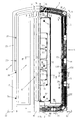
- FIG. 2 shows a preferred embodiment of the device 1 according to the invention shown in partial section.
- the detector gate 4 is - roughly speaking - from two sections: an outer, frame-like part 10 and an inner Part 11, which is arranged between the lower and upper part of the frame.
- the outer part 10 is the transmitter 5 and in the inner part 11 is the Receiving device 6 arranged.
- Both the outer part 10 and the inner part Part 11 consist of two joinable, shell-shaped frame halves 23, 24 for receiving the transmitting device 5 and the receiving device (s) 6 serve.
- On the two lateral areas of the outer part 10 are Holding elements 17 attached.
- the floor brackets 22 for example consist of a bolt anchored in the ground and a nut, the Holding elements 17 fixed.
- the transmitting device 5 consists of eighteen turns 12, which according to the invention are divided into two groups 13a, 13b of turns 12. In the case shown, each of the two groups 13a, 13b has the same number of turns 12. In general, however, the subdivision of the turns 12 into groups 13a, 13b is possible in any constellation.
- the gap 15 between the two groups 13a, 13b of turns 12 is closed Spacers 14 created that are longitudinally spaced apart from each other the coil turns 12 are arranged.
- the spacers 14 have in the area
- the gap 15 created by them each has a bore 28 which is for receiving a screw 29 is used. These screws 29 also have the function of to connect the two frame halves 23, 24 to one another.
- the turns 12 are a top view of the front or the Rear of the detector gate 4 arranged side by side.
- the transmitting device 5 operates also excellent if the turns 12 - in the direction of view of the front or Rear of the detector gate 4 - are arranged one behind the other.
- the inductance of the transmitting device 5 embodying coil significantly reduced.
- the transmission device 5 is computer-controlled by the energy supply 7 in this way energized that an alternating magnetic field with the desired frequencies in surveillance zone 3 is transmitted. These frequencies are - Following EP 0 153 286 B1 - for example around a low frequency in the Hertz range and two radio frequencies in the kilohertz range.
- the computing / control device 8 is in the form of a computer card housed in the lower part of the detector gate 4 and from the outside after opening the Flap 16 freely accessible.
- the lower part of the detector gate 4 is such designed to have a space between the outer group 13a Turns 12 and the bottom. There is sufficient space in this free space 30 for cables that are placed on the detector gate 4 from the outside.
- the flap 16 is closed, there is sufficient space between the Groups 13a, 13b of turns 12 and the flap 16 itself, so that the of outside cable easily to the computing / control device 8, here a computer card, can be performed.
- the undercover leadership of the Cable rounds off the overall harmonic impression of the detector gate 4.
- the receiving device 6 is - as already mentioned - in the inner part 11 of the Detector gate 4 arranged.
- the receiving device 6 exists according to one particularly favorable embodiment of three combined with each other Receiver coils 18, 19.20.
- the receiver coil 18 consists of two horizontally adjacent loops 21 which are connected in series, so that the The current flows through windings in opposite directions. So while the receiver coil 18 embodies a horizontal "figure eight", the receiver coil 19 consists of a vertical "eight”, and the Receiver coil 20 is effectively composed of two "eighties" lying one below the other, a so-called offset eight, together.
- the shapes of the selected receiver coils 18, 19, 20, especially in combination, provide a sufficient detection rate for an electronic security element 2 in the entire area of Surveillance zone 3 safe. All three receiver coils couple only slightly Measure with each other or with the transmitter 5. Furthermore, they stand out - how already described in the previous place - in that they are relative are insensitive to far fields from outside the surveillance zone 3 come from.
- Pins 33 are arranged in the region of the inner part 10. These pins 33 serve the purpose, the turns 12 of the receiver coils 18, 19, 20 in the fix desired positions.
- the shape of the receiver coils 18, 19, 20 is chosen such that it sensitivity of quadrupole fields. This constellation is sufficient Sensitivity of the receiving device 6 in the central region of the detector gate 4 achieved even with small dimensions. In addition, interference signals switch off from far fields to a sufficient extent so that the Detection rate for the security elements passing the surveillance zone 2 is optimal.
- the receiving device 6 receives a signal which the computing / control device 8 subsequently recognizes as a characteristic signal emitted by a security element 2, it sends a pulse to the alarm device 9, which is then acoustically via the two buzzer 25 and / or optically by means of the Flashing light 26 indicates the unauthorized stay of an electronically secured article in the surveillance zone 3.
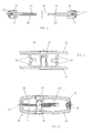
- the alarm device 9 is clearly visible in FIG. 3, which shows a top view of the detector gate 4 from above. Furthermore, the recess between the two shell-shaped frame halves 23, 24 can be seen in FIG. 3. It is sealed by a so-called piping 27, an elastic closure.
- the holding elements 17 attached in the lower area of the outer part 10 of the detector gate 4 are anchored in the floor by means of the floor brackets 22.
- the adjusting screws 37 are used for fine alignment of the detector gate 4.
- FIG. 4 to 12 show those in FIG. 2 with corresponding Roman numerals marked cuts.
- Fig. 4 is a section through an upper corner of the outer part 10 of the detector gate 4 shown.
- the inside of the two frame halves 23, 24 attached webs 31 serve a lateral To create a limit for the turns 12 of the inner group 13b. Otherwise they contribute to the stability of the outer part 10 of the two frame halves 23, 24.
- the two frame halves 23, 24 are secured by means of screws 29 which are passed through bores 28 are screwed together.
- Fig. 5 shows a cross section through the upper corner of the outer part 10 of the Detector gate 4.
- the two frame halves 23, 24 have holes 28 for Take up the screws 29.
- the holes 28 and the screws 29 are in the Area of the gap 15 between the two groups 13a, 13b of turns 12 arranged.
- some of the screws 29 fix the spacers 14 in the desired positions.
- These spacers 14 are elements made of plastic, one in the area of the gap 15 through the bore 28 pierced Have area and that in the area of the outer group 13a of turns 12 have a slot for receiving the turns 12.
- the one of the two Frame halves 23, 24 left recess at the edge of the outer part 10 is sealed by an elastic closure element, a so-called piping 27.
- 6 is a cross section through the outer part 10 of the detector gate 4 in Area of the lateral holding elements 17 reproduced. 7 relates to a parallel section in the area of a spacer 14.
- Fig. 8 is a section through the bottom part of the outer part 10 of the Detector gate 4 shown. In addition to those already in the previous Parts described in this drawing is the free space 30 in FIG See the lines.
- FIG. 9 shows a section through the inner part 11 of the detector gate 4 according to FIG the marking IX-IX in Fig. 2.
- the receiver coils 18, 19, 20 can be seen.
- the individual turns 12 are in Clamping elements 35 out.
- Fig. 10 shows a cross section through the area that the acoustic part of the Alarm device 9 contains. In particular, the two are in this drawing Buzzer 25 shown.
- FIG. 11 shows a section through the optical part of the alarm device 9.
- a housing that is covered by a transparent, colored cap 34, is (are) one (or two) flashing light (s) 26 arranged, the (the) in combination with the two buzzer 25 not to be overlooked or not to be overheard Sends out alarm signals as soon as the computing / control device 8 characteristic signal of a security element 2 in the monitoring zone 3 matters.
- Fig. 12 shows the section according to the identification XII-XII in Fig. 2 in the area one of the six alignment means 32, which in the inner part 11 of the detector gate 4 are to be found.
- this alignment means 32 it is about this alignment means 32 to elements that join the two Lighten the frame halves 23, 24 after mounting the receiving device (s) 6 should.
- the alignment means 32 is two elements that fit snugly into one another, one of these elements on the Inside of the front frame half 23 and the other element on the Inside the rear frame half 24 is attached.
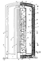
- FIG. 13 shows a further embodiment of the device according to the invention shown. It differs from the previously described embodiment only by the type of attachment of the turns 12 of the transmitter device 5. In the lower and upper area of the frame is still attached about the spacers 14. In the side areas these are separated by two webs 38 running between the two groups 13a, 13b of turns 12, 39 replaced.
- the stability of the Detector gate 4 reached against external influences. Optimize can the stability of the detector gate 4 by inserting a rod 40 a hard material in the space between the two webs 38, 39.
- FIGS. 14, 15 and 16 show those identified in FIG. 13 Cuts. All further details of the embodiment of the figures Fig. 13, Fig. 14, 15 and 16 correspond to those shown in the previous figures Details.
Landscapes
- Engineering & Computer Science (AREA)
- Physics & Mathematics (AREA)
- Signal Processing (AREA)
- Automation & Control Theory (AREA)
- Computer Security & Cryptography (AREA)
- Electromagnetism (AREA)
- General Physics & Mathematics (AREA)
- Burglar Alarm Systems (AREA)
Description
Eine räumlich gedrängte Anordnung von Detektorgattern im Eingangs- und Ausgangsbereich stört jedoch den optischen Eindruck, den der Kunde beim Betreten des Kaufhauses gewinnt: sie suggeriert Enge und Eingesperrtsein. Damit wirkt der Eingangsbereich wenig einladend auf die Kundschaft. Dieser Eindruck wird verstärkt, wenn die Detektorgatter nicht durchsichtig ausgebildet sind. Darüber hinaus wird durch die eng beieinander stehenden Detektorgatter der Durchgangsverkehr im Eingangs- und Ausgangsbereich behindert.
Von der anderen Seite betrachtet, bedeutet dies, daß die Breite der Zone, die von der erfindungsgemäßen Einrichtung sicher überwacht werden kann, größer wählbar ist als diejenige, die bislang von einer Einrichtung des Standes der Technik sicher überwacht werden konnte.
Eine alternative Lösung schlägt zur Erhöhung der Stabilität des Detektorgatters folgendes vor: bei der Befestigung der Windungen der Sendevorrichtung ist zumindest in den beiden Seitenbereichen des Detektorgatters anstelle der Abstandhalter eine durch beidseitig angeordnete Stege gebildete Nut vorgesehen. In diese Nut wird nach der Montage ein Stab aus hartem Material eingeschoben.
Alternativ ist es selbstverständlich auch möglich, die Sendevorrichtung und die Empfangsvorrichtung(en) in separaten Detektorgattern anzuordnen.
Die Sendevorrichtung 5 besteht aus achtzehn Windungen 12, die gemäß der Erfindung in zwei Gruppen 13a, 13b von Windungen 12 unterteilt sind. Im gezeigten Fall hat jede der beiden Gruppen 13a, 13b jeweils die gleiche Anzahl von Windungen 12. Generell ist die Unterteilung der Windungen 12 in Gruppen 13a, 13b jedoch in beliebigen Konstellationen möglich.
Wo erforderlich, werden bei den einzelnen Schritten die Windungen 12 der Gruppen 13a, 13b elektrisch angeschlossen.
Weiterhin ist in Fig. 3 die Ausnehmung zwischen den beiden schalenförmigen Rahmenhälften 23, 24 ersichtlich. Sie wird durch einen sog. Keder 27, einen elastischen Verschluß, abgedichtet. Die im unteren Bereich des äußeren Teils 10 des Detektorgatters 4 angebrachten Halteelemente 17 werden mittels der Bodenhalterungen 22 im Boden verankert. Die Justierschrauben 37 dienen zur Feinausrichtung des Detektorgatters 4.
- 1
- Detektoreinrichtung
- 2
- Sicherungselement
- 3
- Überwachungszone
- 4
- Detektorgatter
- 5
- Sendevorrichtung
- 6
- Empfangsvorrichtung
- 7
- Energieversorgung
- 8
- Rechen-/Ansteuereinrichtung
- 9
- Alarmeinrichtung
- 10
- äußerer Teil
- 11
- innerer Teil
- 12
- Windung
- 13a
- äußere Gruppe
- 13b
- innere Gruppe
- 14
- Abstandhalter
- 15
- Lücke
- 16
- Klappe
- 17
- Halteelement
- 18
- Empfängerspule
- 19
- Empfängerspule
- 20
- Empfängerspule
- 21
- Schleife
- 22
- Bodenhalterung
- 23
- vordere Rahmenhälfte
- 24
- hintere Rahmenhälfte
- 25
- Buzzer
- 26
- Blinklicht
- 27
- Keder
- 28
- Bohrung
- 29
- Schraube
- 30
- Freiraum
- 31
- Steg
- 32
- Ausrichtemittel
- 33
- Stift
- 34
- transparente Kappe
- 35
- Klemmelement
- 36
- Schraube
- 37
- Justierschraube
- 38
- Steg
- 39
- Steg
- 40
- Stab
Claims (13)
- Einrichtung zur Detektierung eines mit einem elektronischen Sicherungselement (2) versehenen Artikels in einer Überwachungszone (3) mit mindestens einer Sendevorrichtung (5), die ein magnetisches Wechselfeld emittiert, das das elektronische Sicherungselement zur Aussendung eines charakteristischen Signals anregt, und mit mindestens einer Empfangsvorrichtung (6), die beim Empfang des charakteristischen Signals einen Alarm auslöst, wobei die Sendevorrichtung (5) eine Spule mit mehreren Windungen (12) aufweist,
dadurch gekennzeichnet,wobei die beiden Gruppen (13a, 13b) in einem Abstand (15) voneinander angeordnet sind.daß die Windungen (12) im wesentlichen in einer Ebene liegen unddaß die Windungen (12) in mindestens zwei Gruppen (13a, 13b) unterteilt sind, - Einrichtung nach Anspruch 1,
dadurch gekennzeichnet,
daß die Windungen (12) in einer senkrecht zur Durchgangsrichtung durch die Überwachungszone (3) liegenden Ebene angeordnet sind. - Einrichtung nach Anspruch 1 oder 2,
dadurch gekennzeichnet,
daß Abstandhalter (14) vorgesehen sind, die die beiden Gruppen (13a, 13b) von Windungen (12) räumlich voneinander trennen. - Einrichtung nach Anspruch 1,
dadurch gekennzeichnet,
daß zwischen den beiden Gruppen (13a, 13b) von Windungen (12) zwei eine Nut bildende Stege (38, 39) vorgesehen sind. - Einrichtung nach Anspruch 4,
dadurch gekennzeichnet,
daß ein Stab (40) aus einem harten Material vorgesehen ist, der in die zwischen den beiden Stegen (38, 39) gebildete Nut einschiebbar ist. - Einrichtung nach Anspruch 1 oder 2,
dadurch gekennzeichnet,
daß die Sendevorrichtung (5) und zumindest eine Empfangsvorrichtung (6) in einem eine Einheit bildenden Detektorgatter (4) angeordnet sind. - Einrichtung nach Anspruch 1 oder 2,
dadurch gekennzeichnet,
daß die Sendevorrichtung (5) und die Empfangsvorrichtung(en) (6) in separaten Detektorgattern (4) angeordnet sind. - Einrichtung nach Anspruch 1 oder 2,
dadurch gekennzeichnet,
daß die Windungen (12) der Spule der Sendevorrichtung (5) aus Litze-Draht gefertigt sind. - Einrichtung nach Anspruch 1 oder 6,
dadurch gekennzeichnet,
daß das Detektorgatter (4) aus einem äußeren Teil (11) und einem inneren Teil (10) besteht, wobei die Sendevorrichtung (5) in dem äußeren Teil (11) und die Empfangsvorrichtung(en) (6) vorzugsweise in dem inneren Teil (10) des Detektorgatters (4) untergebracht ist (sind). - Einrichtung nach Anspruch 1 oder 9,
dadurch gekennzeichnet,
daß die Empfangsvorrichtung(en) (6) eine wesentlich geringere Flächenausdehnung als die Sendevorrichtung (5) aufweist (aufweisen). - Einrichtung nach Anspruch 10,
dadurch gekennzeichnet,
daß die Empfangsvorrichtung (6) zumindest eine Windung (12) aufweist, die derart gebogen ist, daß sie im wesentlichen eine Quadrupol-Charakteristik aufweist. - Einrichtung nach Anspruch 1,
dadurch gekennzeichnet,
daß die Empfangsvorrichtung (6) die Form einer "Acht" aufweist, wobei die beiden Teilbereiche der "Acht" nebeneinander oder untereinander angeordnet sind. - Einrichtung nach Anspruch 1,
dadurch gekennzeichnet,daß es sich bei dem elektronischen Sicherungselement (2) um ein Element handelt,das aus einem weichmagnetischen Material mit hoher Permeabilität und geringer Koerzitivkraft gefertigt ist, oder daß das Material magnetostriktive Eigenschaften besitzt, oder aber daß es sich bei dem Sicherungselement (2) um ein Element mit einem Resonanzschwingkreis handelt.
Applications Claiming Priority (2)
| Application Number | Priority Date | Filing Date | Title |
|---|---|---|---|
| DE19503896A DE19503896A1 (de) | 1995-02-07 | 1995-02-07 | Einrichtung zur Detektierung eines mit einem elektronischen Sicherungselement versehenen Artikels |
| DE19503896 | 1995-02-07 |
Publications (3)
| Publication Number | Publication Date |
|---|---|
| EP0726549A2 EP0726549A2 (de) | 1996-08-14 |
| EP0726549A3 EP0726549A3 (de) | 1996-11-06 |
| EP0726549B1 true EP0726549B1 (de) | 2000-05-03 |
Family
ID=7753312
Family Applications (1)
| Application Number | Title | Priority Date | Filing Date |
|---|---|---|---|
| EP96100686A Expired - Lifetime EP0726549B1 (de) | 1995-02-07 | 1996-01-18 | Einrichtung zur Detektierung eines mit einem elektronischen Sicherungselement versehenen Artikels |
Country Status (5)
| Country | Link |
|---|---|
| EP (1) | EP0726549B1 (de) |
| AU (1) | AU695927B2 (de) |
| DE (2) | DE19503896A1 (de) |
| DK (1) | DK0726549T3 (de) |
| ES (1) | ES2148599T3 (de) |
Families Citing this family (4)
| Publication number | Priority date | Publication date | Assignee | Title |
|---|---|---|---|---|
| DE19722078A1 (de) * | 1997-05-27 | 1998-12-03 | Meto International Gmbh | System zur Überwachung von elektromagnetisch gesicherten Artikeln in mehreren Überwachungszonen |
| DE19726986A1 (de) * | 1997-06-25 | 1999-01-07 | Meto International Gmbh | Vorrichtung zur Überwachung von elektronischen gesicherten Artikeln in einer Überwachungszone |
| DE19732558A1 (de) * | 1997-07-29 | 1999-02-04 | Meto International Gmbh | Verfahren und Vorrichtung zur Wicklung einer Sende- oder Empfangsspule für ein elektronisches Artikelüberwachungssystem |
| DE19858714A1 (de) | 1998-12-18 | 2000-06-21 | Ebinger Klaus Ing Fa | Torsonde |
Family Cites Families (11)
| Publication number | Priority date | Publication date | Assignee | Title |
|---|---|---|---|---|
| US3820104A (en) * | 1972-12-15 | 1974-06-25 | Stop Loss Inc | Method and system for detecting an object within a magnetic field interrogation zone |
| US4016553A (en) * | 1975-06-27 | 1977-04-05 | Knogo Corporation | Article detection system with near field electromagnetic wave control |
| US4118693A (en) * | 1977-05-09 | 1978-10-03 | Knogo Corporation | Method and apparatus for producing uniform electromagnetic fields in an article detection system |
| US4260990A (en) * | 1979-11-08 | 1981-04-07 | Lichtblau G J | Asymmetrical antennas for use in electronic security systems |
| US4623877A (en) * | 1983-06-30 | 1986-11-18 | Knogo Corporation | Method and apparatus for detection of targets in an interrogation zone |
| US4509039A (en) * | 1983-07-05 | 1985-04-02 | Minnesota Mining And Manufacturing Company | Shielded, closely spaced transmit-receiver antennas for electronic article surveillance system |
| GB8808933D0 (en) * | 1988-04-15 | 1988-05-18 | Scient Generics Ltd | Antipilferage system |
| US4994939A (en) * | 1989-11-15 | 1991-02-19 | Minnesota Mining And Manufacturing Company | Universal lattice for magnetic-electronic article surveillance system |
| US5051726A (en) * | 1990-08-14 | 1991-09-24 | Sensormatic Electronics Corporation | Electronic article surveillance system with antenna array for enhanced field falloff |
| NL9100397A (nl) * | 1991-03-06 | 1992-10-01 | Nedap Nv | Asymmetrische antenne voor winkeldiefstaldetectiesystemen. |
| GB9125846D0 (en) * | 1991-12-04 | 1992-02-05 | Esselte Meto Int Gmbh | Improved interrogation and detection means for theft-detection systems |
-
1995
- 1995-02-07 DE DE19503896A patent/DE19503896A1/de not_active Withdrawn
- 1995-12-20 AU AU40582/95A patent/AU695927B2/en not_active Ceased
-
1996
- 1996-01-18 DK DK96100686T patent/DK0726549T3/da active
- 1996-01-18 DE DE59605082T patent/DE59605082D1/de not_active Expired - Fee Related
- 1996-01-18 ES ES96100686T patent/ES2148599T3/es not_active Expired - Lifetime
- 1996-01-18 EP EP96100686A patent/EP0726549B1/de not_active Expired - Lifetime
Also Published As
| Publication number | Publication date |
|---|---|
| EP0726549A3 (de) | 1996-11-06 |
| DE19503896A1 (de) | 1996-08-08 |
| EP0726549A2 (de) | 1996-08-14 |
| ES2148599T3 (es) | 2000-10-16 |
| DE59605082D1 (de) | 2000-06-08 |
| AU695927B2 (en) | 1998-08-27 |
| DK0726549T3 (da) | 2000-09-04 |
| AU4058295A (en) | 1996-08-15 |
Similar Documents
| Publication | Publication Date | Title |
|---|---|---|
| DE3233028C2 (de) | ||
| DE2737129C3 (de) | Vorrichtung zur Ermittlung eines sich innerhalb eines Überwachungsbereichs befindlichen Gegenstandes | |
| DE3715387C2 (de) | ||
| DE2837637C3 (de) | Elektronisches Diebstahl-Sicherungssystem zur Überwachung breiter Durchgänge | |
| DE68921745T2 (de) | Antennen-struktur für elektronisches bewachungssystem für gegenstände. | |
| DE69414751T2 (de) | Gitterantenne für elektronisches Gegenstand-Überwachungssystem | |
| DE69112317T2 (de) | Elektronische Warenüberwachungsanlage und Antennenstruktur dafür. | |
| DE69312974T2 (de) | Laminat und seine anwendung | |
| DE2820166B2 (de) | Vorrichtung und Verfahren zum Entdecken des unerlaubten Vorbeiführens von Waren | |
| DE2804692A1 (de) | Magnetanzeigeeinrichtung | |
| DE69701728T2 (de) | Sensor für ferngesteuerte detektion von objekten | |
| DE69019106T2 (de) | Universales Gitter für eine magnetisch elektronische Warenüberwachungsanlage. | |
| EP1702409B1 (de) | Sicherheitsschalter zum überwachen einer schliessposition zweier relativ zueinander beweglicher teile | |
| EP0726549A2 (de) | Einrichtung zur Detektierung eines mit einem elektronischen Sicherungselement versehenen Artikels | |
| EP0789340B1 (de) | Sicherungselement für die elektronische Artikelsicherung | |
| DE2033796A1 (de) | System zum Feststellen einer Kenn Zeichnungsvorrichtung | |
| DE60128236T2 (de) | Folienelement und seine anwendung | |
| EP0770249A1 (de) | Kontrolleinrichtung | |
| EP1224640B1 (de) | Sicherungselement für die elektronische artikelsicherung | |
| EP0450399B1 (de) | Safe, insbesondere Schliessfach, mit elektrischer Fernbetätigung | |
| EP0992029B1 (de) | Vorrichtung zur überwachung von elektronisch gesicherten artikeln in einer überwachungszone | |
| DE3851056T2 (de) | Fühlerelement für ein alarmsystem. | |
| DE102004052543A1 (de) | Warensicherungseinrichtung mit Mehrfachsicherung | |
| DE69127000T2 (de) | Wandstruktur | |
| DE19822670A1 (de) | Vorrichtung für die elektronische Überwachung von Artikeln |
Legal Events
| Date | Code | Title | Description |
|---|---|---|---|
| PUAI | Public reference made under article 153(3) epc to a published international application that has entered the european phase |
Free format text: ORIGINAL CODE: 0009012 |
|
| AK | Designated contracting states |
Kind code of ref document: A2 Designated state(s): BE DE DK ES FR GB IT NL SE |
|
| PUAL | Search report despatched |
Free format text: ORIGINAL CODE: 0009013 |
|
| AK | Designated contracting states |
Kind code of ref document: A3 Designated state(s): BE DE DK ES FR GB IT NL SE |
|
| 17P | Request for examination filed |
Effective date: 19970211 |
|
| RAP1 | Party data changed (applicant data changed or rights of an application transferred) |
Owner name: METO INTERNATIONAL GMBH |
|
| GRAG | Despatch of communication of intention to grant |
Free format text: ORIGINAL CODE: EPIDOS AGRA |
|
| 17Q | First examination report despatched |
Effective date: 19990831 |
|
| GRAG | Despatch of communication of intention to grant |
Free format text: ORIGINAL CODE: EPIDOS AGRA |
|
| GRAH | Despatch of communication of intention to grant a patent |
Free format text: ORIGINAL CODE: EPIDOS IGRA |
|
| GRAH | Despatch of communication of intention to grant a patent |
Free format text: ORIGINAL CODE: EPIDOS IGRA |
|
| GRAA | (expected) grant |
Free format text: ORIGINAL CODE: 0009210 |
|
| AK | Designated contracting states |
Kind code of ref document: B1 Designated state(s): BE DE DK ES FR GB IT NL SE |
|
| REF | Corresponds to: |
Ref document number: 59605082 Country of ref document: DE Date of ref document: 20000608 |
|
| ITF | It: translation for a ep patent filed | ||
| ET | Fr: translation filed | ||
| GBT | Gb: translation of ep patent filed (gb section 77(6)(a)/1977) |
Effective date: 20000807 |
|
| REG | Reference to a national code |
Ref country code: DK Ref legal event code: T3 |
|
| REG | Reference to a national code |
Ref country code: ES Ref legal event code: FG2A Ref document number: 2148599 Country of ref document: ES Kind code of ref document: T3 |
|
| PLBE | No opposition filed within time limit |
Free format text: ORIGINAL CODE: 0009261 |
|
| STAA | Information on the status of an ep patent application or granted ep patent |
Free format text: STATUS: NO OPPOSITION FILED WITHIN TIME LIMIT |
|
| 26N | No opposition filed | ||
| REG | Reference to a national code |
Ref country code: GB Ref legal event code: IF02 |
|
| PGFP | Annual fee paid to national office [announced via postgrant information from national office to epo] |
Ref country code: DK Payment date: 20031211 Year of fee payment: 9 |
|
| PG25 | Lapsed in a contracting state [announced via postgrant information from national office to epo] |
Ref country code: DK Free format text: LAPSE BECAUSE OF NON-PAYMENT OF DUE FEES Effective date: 20050131 |
|
| REG | Reference to a national code |
Ref country code: DK Ref legal event code: EBP |
|
| PGFP | Annual fee paid to national office [announced via postgrant information from national office to epo] |
Ref country code: SE Payment date: 20070129 Year of fee payment: 12 |
|
| EUG | Se: european patent has lapsed | ||
| PGFP | Annual fee paid to national office [announced via postgrant information from national office to epo] |
Ref country code: IT Payment date: 20080129 Year of fee payment: 12 |
|
| PG25 | Lapsed in a contracting state [announced via postgrant information from national office to epo] |
Ref country code: SE Free format text: LAPSE BECAUSE OF NON-PAYMENT OF DUE FEES Effective date: 20080119 |
|
| PGFP | Annual fee paid to national office [announced via postgrant information from national office to epo] |
Ref country code: ES Payment date: 20090126 Year of fee payment: 14 |
|
| PGFP | Annual fee paid to national office [announced via postgrant information from national office to epo] |
Ref country code: NL Payment date: 20090124 Year of fee payment: 14 Ref country code: DE Payment date: 20090302 Year of fee payment: 14 |
|
| PGFP | Annual fee paid to national office [announced via postgrant information from national office to epo] |
Ref country code: GB Payment date: 20090129 Year of fee payment: 14 |
|
| PGFP | Annual fee paid to national office [announced via postgrant information from national office to epo] |
Ref country code: BE Payment date: 20090219 Year of fee payment: 14 |
|
| PG25 | Lapsed in a contracting state [announced via postgrant information from national office to epo] |
Ref country code: IT Free format text: LAPSE BECAUSE OF NON-PAYMENT OF DUE FEES Effective date: 20080118 |
|
| PGFP | Annual fee paid to national office [announced via postgrant information from national office to epo] |
Ref country code: FR Payment date: 20090119 Year of fee payment: 14 |
|
| BERE | Be: lapsed |
Owner name: *METO INTERNATIONAL G.M.B.H. Effective date: 20100131 |
|
| REG | Reference to a national code |
Ref country code: NL Ref legal event code: V1 Effective date: 20100801 |
|
| GBPC | Gb: european patent ceased through non-payment of renewal fee |
Effective date: 20100118 |
|
| REG | Reference to a national code |
Ref country code: FR Ref legal event code: ST Effective date: 20100930 |
|
| PG25 | Lapsed in a contracting state [announced via postgrant information from national office to epo] |
Ref country code: NL Free format text: LAPSE BECAUSE OF NON-PAYMENT OF DUE FEES Effective date: 20100801 Ref country code: FR Free format text: LAPSE BECAUSE OF NON-PAYMENT OF DUE FEES Effective date: 20100201 |
|
| PG25 | Lapsed in a contracting state [announced via postgrant information from national office to epo] |
Ref country code: DE Free format text: LAPSE BECAUSE OF NON-PAYMENT OF DUE FEES Effective date: 20100803 |
|
| PG25 | Lapsed in a contracting state [announced via postgrant information from national office to epo] |
Ref country code: GB Free format text: LAPSE BECAUSE OF NON-PAYMENT OF DUE FEES Effective date: 20100118 |
|
| PG25 | Lapsed in a contracting state [announced via postgrant information from national office to epo] |
Ref country code: BE Free format text: LAPSE BECAUSE OF NON-PAYMENT OF DUE FEES Effective date: 20100131 |
|
| REG | Reference to a national code |
Ref country code: ES Ref legal event code: FD2A Effective date: 20110224 |
|
| PG25 | Lapsed in a contracting state [announced via postgrant information from national office to epo] |
Ref country code: ES Free format text: LAPSE BECAUSE OF NON-PAYMENT OF DUE FEES Effective date: 20110223 |
|
| PG25 | Lapsed in a contracting state [announced via postgrant information from national office to epo] |
Ref country code: ES Free format text: LAPSE BECAUSE OF NON-PAYMENT OF DUE FEES Effective date: 20100119 |