EP0726344B1 - Procédé et dispositif pour commander un métier à tisser - Google Patents
Procédé et dispositif pour commander un métier à tisser Download PDFInfo
- Publication number
- EP0726344B1 EP0726344B1 EP95810085A EP95810085A EP0726344B1 EP 0726344 B1 EP0726344 B1 EP 0726344B1 EP 95810085 A EP95810085 A EP 95810085A EP 95810085 A EP95810085 A EP 95810085A EP 0726344 B1 EP0726344 B1 EP 0726344B1
- Authority
- EP
- European Patent Office
- Prior art keywords
- signal
- angular position
- representing
- weaving machine
- control device
- Prior art date
- Legal status (The legal status is an assumption and is not a legal conclusion. Google has not performed a legal analysis and makes no representation as to the accuracy of the status listed.)
- Expired - Lifetime
Links
- 238000000034 method Methods 0.000 title claims description 14
- 238000009941 weaving Methods 0.000 claims description 32
- 238000004891 communication Methods 0.000 claims description 5
- 230000005540 biological transmission Effects 0.000 claims description 4
- 238000005259 measurement Methods 0.000 claims 2
- 238000012544 monitoring process Methods 0.000 claims 2
- 230000007704 transition Effects 0.000 claims 1
- 108010076504 Protein Sorting Signals Proteins 0.000 description 4
- 230000001360 synchronised effect Effects 0.000 description 4
- 238000010586 diagram Methods 0.000 description 3
- 230000002123 temporal effect Effects 0.000 description 2
- 239000012530 fluid Substances 0.000 description 1
- 238000003780 insertion Methods 0.000 description 1
- 230000037431 insertion Effects 0.000 description 1
- 239000010453 quartz Substances 0.000 description 1
- VYPSYNLAJGMNEJ-UHFFFAOYSA-N silicon dioxide Inorganic materials O=[Si]=O VYPSYNLAJGMNEJ-UHFFFAOYSA-N 0.000 description 1
- 238000013024 troubleshooting Methods 0.000 description 1
Images

Classifications
-
- G—PHYSICS
- G05—CONTROLLING; REGULATING
- G05B—CONTROL OR REGULATING SYSTEMS IN GENERAL; FUNCTIONAL ELEMENTS OF SUCH SYSTEMS; MONITORING OR TESTING ARRANGEMENTS FOR SUCH SYSTEMS OR ELEMENTS
- G05B19/00—Programme-control systems
- G05B19/02—Programme-control systems electric
- G05B19/04—Programme control other than numerical control, i.e. in sequence controllers or logic controllers
- G05B19/042—Programme control other than numerical control, i.e. in sequence controllers or logic controllers using digital processors
- G05B19/0421—Multiprocessor system
-
- D—TEXTILES; PAPER
- D03—WEAVING
- D03D—WOVEN FABRICS; METHODS OF WEAVING; LOOMS
- D03D51/00—Driving, starting, or stopping arrangements; Automatic stop motions
- D03D51/005—Independent drive motors
-
- D—TEXTILES; PAPER
- D03—WEAVING
- D03D—WOVEN FABRICS; METHODS OF WEAVING; LOOMS
- D03D51/00—Driving, starting, or stopping arrangements; Automatic stop motions
- D03D51/007—Loom optimisation
-
- D—TEXTILES; PAPER
- D03—WEAVING
- D03D—WOVEN FABRICS; METHODS OF WEAVING; LOOMS
- D03D51/00—Driving, starting, or stopping arrangements; Automatic stop motions
- D03D51/06—Driving, starting, or stopping arrangements; Automatic stop motions using particular methods of stopping
- D03D51/08—Driving, starting, or stopping arrangements; Automatic stop motions using particular methods of stopping stopping at definite point in weaving cycle, or moving to such point after stopping
-
- G—PHYSICS
- G05—CONTROLLING; REGULATING
- G05B—CONTROL OR REGULATING SYSTEMS IN GENERAL; FUNCTIONAL ELEMENTS OF SUCH SYSTEMS; MONITORING OR TESTING ARRANGEMENTS FOR SUCH SYSTEMS OR ELEMENTS
- G05B2219/00—Program-control systems
- G05B2219/20—Pc systems
- G05B2219/25—Pc structure of the system
- G05B2219/25045—Electronic cam, encoder for sequence control as function of position, programmable switch pls
-
- G—PHYSICS
- G05—CONTROLLING; REGULATING
- G05B—CONTROL OR REGULATING SYSTEMS IN GENERAL; FUNCTIONAL ELEMENTS OF SUCH SYSTEMS; MONITORING OR TESTING ARRANGEMENTS FOR SUCH SYSTEMS OR ELEMENTS
- G05B2219/00—Program-control systems
- G05B2219/20—Pc systems
- G05B2219/25—Pc structure of the system
- G05B2219/25053—Frequency pulses as function of speed
-
- G—PHYSICS
- G05—CONTROLLING; REGULATING
- G05B—CONTROL OR REGULATING SYSTEMS IN GENERAL; FUNCTIONAL ELEMENTS OF SUCH SYSTEMS; MONITORING OR TESTING ARRANGEMENTS FOR SUCH SYSTEMS OR ELEMENTS
- G05B2219/00—Program-control systems
- G05B2219/20—Pc systems
- G05B2219/25—Pc structure of the system
- G05B2219/25144—Between microcomputers, processors
-
- G—PHYSICS
- G05—CONTROLLING; REGULATING
- G05B—CONTROL OR REGULATING SYSTEMS IN GENERAL; FUNCTIONAL ELEMENTS OF SUCH SYSTEMS; MONITORING OR TESTING ARRANGEMENTS FOR SUCH SYSTEMS OR ELEMENTS
- G05B2219/00—Program-control systems
- G05B2219/20—Pc systems
- G05B2219/25—Pc structure of the system
- G05B2219/25475—Sequence synchronized with machine axis, like knitting machine
-
- G—PHYSICS
- G05—CONTROLLING; REGULATING
- G05B—CONTROL OR REGULATING SYSTEMS IN GENERAL; FUNCTIONAL ELEMENTS OF SUCH SYSTEMS; MONITORING OR TESTING ARRANGEMENTS FOR SUCH SYSTEMS OR ELEMENTS
- G05B2219/00—Program-control systems
- G05B2219/20—Pc systems
- G05B2219/25—Pc structure of the system
- G05B2219/25483—Synchronize several controllers using messages over data bus
Definitions
- the invention relates to a method for operating a Loom according to the preamble of claim 1. Die The invention further relates to a device for operation a loom according to the preamble of claim 7.
- EP 0 547 004 describes a method and a method Device for operating a loom known the drives and actuators of a weaving machine in each case individually controlled by a subordinate computer , these subordinate computers via a serial data line with a superordinate computer which are the required data and Control commands to operate the loom to the subordinate computer supplies.
- a Angle encoder of the angle of rotation of the main shaft of the weaving machine detected, and this angle signal to each subordinate Computer and the parent computer forwarded.
- the invention has for its object this disadvantage to fix.
- the object of the invention is achieved in that a Angle generator an artificial, electronic Angle signal generated, and that this angle signal over a line to the subordinate computers and the parent computer is transmitted, so that Artificially generated angle signal as a reference for the Drives and actuators.
- the angle signal will no longer with, as is known from the prior art an angle encoder on the main shaft of the loom tapped, but in a synthetic, artificial way generated, for example with the help of a quartz. All The drives and actuators of the weaving machine are aligned after this artificial angle signal.
- An advantage of Invention can be seen in the fact that the artificial Angle signal as a kind of synthetic guide wave can be used by using the angle signal as a Serves reference signal, according to which a weaving machine together with all drives and actuators can.
- angle signal is no longer from the movement the main shaft is determined, but independently of it is.
- This enables a large number of possible courses of Angle signals can be specified as a function of time. For example, when starting or braking, a ramped angular velocity in Function of time can be specified, according to which all Rotate drives synchronously.
- Another advantage of Invention can be seen in the fact that the individual drives and units can also be individually controlled and positioned so that, for example, when a shot is broken the main shaft stands still and only for troubleshooting necessary components moved and then into a defined position.
- Another advantage The invention is to be seen in that the loom in a defined angular position, for example at 0 degrees of Main shaft that can be stopped because of the advance it can be calculated how the weaving machine has to be driven to stop in this situation. That to slow down required angle signal as a function of time becomes calculated in advance and during the braking process the Predetermined weaving machine.
- Another advantage of Invention is to be seen in that simple Realize so-called electronic gears leave by a gear ratio between the Angle signal and an aggregate to be driven can be specified electronically and can also be changed at any time is. This means, for example, that during operation Loom in crawl a different one Speeds between the main shaft and others Aggregates possible.
- an angle signal Loom preferably the angle of rotation of the main shaft, tapped.
- This measured angle signal becomes one Switching device supplied, which, depending on Operating condition of the weaving machine, either the measured one Angle signal or artificially with the angle generator transmit the generated angle signal to the computers so that this signal as a reference for the drives and Actuators serves.
- This embodiment thus allows it to choose whether the actual angle of rotation of the loom or the artificially generated angle signal to the drives and actuators is specified.
- This Switching option has the advantage that for Example during start-up or braking of the Loom the actual angle of rotation is used because due to the inertia, for example, the location the main shaft from an artificially predetermined one Angle signal could deviate. By using the actual angle of rotation can thus during Starting or braking the loom all drives and Actuators synchronous to the angle of rotation of the main shaft are driven.
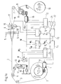
- the weaving machine according to FIG. 1a has a higher-level one Control device CM and a plurality of subordinate control devices C1, C2, C3, C4 and C5.
- the control devices C1, C2, C3, C4, C5, CM each have a computer and are each one Communication device F1, F2, F3, F4, F5, FM to one common data bus L connected, which for Serves to transfer data.
- An angle generator W1 generates an angle signal W2, which is transmitted via a further independent data line W the control devices C1, C2, C3, C4, C5, CM is supplied.
- the angle generator W1 can be part of the parent control device CM form, or also be designed as an independent unit, which in in this case also a communication device would have and with the common data bus L would be associated, in particular, with the parent Control device CM to communicate.
- the Control device C5 is connected to the data line W. connected and receives the angle signal W2.
- the control device C5 receives via the data bus L. further control commands from the parent Control device CM.
- the control device C5 regulates the main drive M of the weaving machine, and monitors the Rotation angle of the main shaft with a rotation angle sensor Ma.
- the control device C4 is in turn with the Data line W and the data bus L connected and drives via a drive 1 to the warp beam 2.
- the Control device C4 with a rotation angle sensor 1a den Angle of rotation of the drive 1 and with a sensor 14 Tension of the warp threads T.
- the warp threads T run over a deflection roller 3, a Tension roller 4, which a tensioning device 11 with Spring element 12 and a deflection device 13 with Sensor 14 includes, and further over the shaft 5, the Goods take-off device 7,8,9 to the goods tree 10.
- Die Control device C2 drives the drive 15 Goods take-off device 8.
- the weft insertion nozzles 17, 18 pull one Weft thread from a weft thread measuring device 19, 20 starting from the control device C1 can be controlled.
- the air pressure as well as the Switch-on time of the fluid nozzles 17, 18 is determined by the Control device C3 specified.
- the higher-level control device CM controls and monitors the entire weaving machine with all drives 1,15,19,20, M and other aggregates 19,20,21,22.
- the Control device CM inputs the angle generator W1 Angular velocity in front of which one corresponding angle signal W2 generated that everyone Control device C1, C2, C3, C4, C5 over the common data line W is supplied.
- Such common data line W is also called a clock bus designated.
- This data line W forms together with the Angle generator W1 a so-called synthetic Guide shaft because the corresponding angle signal W2 the Specifies the angle of rotation according to which all drives and Align the aggregates.
- the angle of rotation is no longer like previously known from the prior art, due to the location the main shaft, but all the drives, including the drive M of the main shaft, follow that angle of rotation predetermined by the angle generator W1.
- the control device CM also exchanges the common data bus L data such as Control commands or the status of aggregates with the subordinate control devices C1, C2, C3, C4, C5 out.
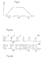
- the artificial angle signal W2 is an electronic or optically transmitted signal, its temporal course shape yourself through a multitude of possibilities leaves.
- 4a is an example of a temporal The course of the artificial angle signal W2 is shown.
- the signal consists of individual, rectangular pulses P, that take place at intervals.
- the signal is defined such that 2048 pulses P of one revolution Correspond to 360 degrees. In the present example the rotation by 360 degrees on the main shaft of the Weaving machine. With every pulse P, the main shaft goes through the drive M by the angle (360 degrees / 2048) turned. The more pulses P occur per unit of time, the more the angular velocity of the main shaft is higher. The Time ⁇ t between the individual pulses P thus determines the angular velocity.
- FIG. 4b shows the course an artificial angle signal W2, which in a first Time range T1 an increase in angular velocity has a constant in a second time period T2 Has angular velocity, and in a third Time range T3 a reduction in the angular velocity having.
- All control devices C1, C2, C3, C4, C5, CM drive the controlled drives to the angle signal W2 following accordingly.
- 3 shows an example a control of the weaving machine.
- the artificial Angle signal W2 is modulated such that in a first time period T1, starting from the standstill of the Loom, a ramped increase in Angular velocity ⁇ results in a second Time range T2 a constant angular velocity ⁇ results, and in a third time period T3 ramped decrease in angular velocity ⁇ results.
- Braking the weaving machine in the third time period T3 can also be done in such a way that the loom in one precisely defined location comes to a standstill.
- pulses P of Angle signal W2 can provide additional information be modulated.
- 2a to 2d each show such a single pulse P with a Extra information.
- the signal sequence P1 the total forms a pulse P, determines that the rotation in Clockwise direction.
- the signal sequence P2 determines that the rotation is counterclockwise. Around Actuators or units are precisely positioned Additional information according to FIG. 2c and FIG. 2d intended.
- the signal sequence P3 indicates that one pass take place at 0 degrees, e.g. related to the main shaft, where the rotation is clockwise.
- the Signal sequence P4 indicates that a pass at 0 degrees takes place, with the rotation counterclockwise he follows.
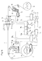
- FIG. 1b shows a block diagram of another Embodiment of a control device.
- the Angle signal W is also common Data bus L to the other control devices C1, C2, C3, C4, C5, CM transmitted. Since the angle signal W is synchronous the parent has to be transmitted Control device CM for that during each Time period in which the angle signal W is to be expected the data bus L from no communication device F1, F2, F3, F4, F5, FM for the transmission of data is used so that the data bus L is free for the Transmission of the angle signal W.
- the angle generator W1 is controlled by the higher-level control device CM controlled, which via the common data bus L are interconnected.
- the control device CM has a switching device, which either the current angle signal W3 or by the Angle generator W1 artificially generated angle signal W2 Data bus L transmitted.
- This switching device has the advantage that, for example, when starting off or Braking the weaving machine the current angle signal W3 the control devices C1, C2, C3, C4, C5 can be specified is.
- the main shaft of a weaving machine can be aground their inertia, for example, during braking generate an angle signal W3 by the artificially generated Angle signal W3 deviates.
- the current Angle signal W3 during braking for example turn the drives 1,15,19,20 and the others Units 19, 20, 21, 22 synchronous to the main shaft.
- the switching device can be part of the parent control device CM form and such act that, according to the embodiment of Fig. 1a, the angle generator W1 either the artificially generated Angle signal W2 or the measured angle signal W3 to the outputs separate data line W. In this embodiment is either the measured angle signal W3 or the artificially generated angle signal W2 on the separate Transfer data line W.
- the inventive method and the The device according to the invention is suitable for different types of weaving machines, for example for Air, projectile, rapier or row shed weaving machines.
Claims (12)
- Procédé de fonctionnement d'un métier à tisser qui comporte une pluralité de dispositifs de commande (C1, C2, C3, C4, C5, CM), chaque dispositif de commande (C1, C2, C3, C4, C5, CM) commandant et/ou surveillant des entraínements (1, 15, M) ou d'autres appareils individuels (19, 20, 21, 22), et où s'applique à chaque dispositif de commande (C1, C2, C3, C4, C5, CM) un signal d'angle commun (W2) servant à la synchronisation des dispositifs d'entraínement (1, 15, M) et des appareils (19, 20, 21, 22), caractérisé en ce que le signal d'angle (W2) est produit artificiellement par un générateur d'angle (W1).
- Procédé selon la revendication 1, caractérisé en ce que le générateur d'angle (W1) est commandé par un dispositif de commande maítre (CM).
- Procédé selon l'une des revendications 1 ou 2, caractérisé en ce que chaque dispositif d'entraínement (1, 15, M) est amené à fonctionner d'une manière synchrone au signal d'angle (W2).
- Procédé selon l'une des revendications 1 à 3. caractérisé en ce qu'on mesure avec un capteur d'angle (Ma) un signal d'angle de rotation (W3) du métier à tisser, de préférence celui de l'arbre principal et en ce qu'on utilise, en fonction de l'état de fonctionnement du métier à tisser, soit le signal d'angle de rotation (W3) soit le signal artificiel produit par le générateur d'angle (W1) comme signal d'angle (W2).
- Procédé selon la revendication 4, caractérisé en ce qu'on utilise pendant le démarrage et/ou le freinage du métier à tisser le signal d'angle de rotation mesuré (W3) comme signal d'angle (W2).
- Procédé selon l'une des revendications 1 à 5, caractérisé en ce qu'on module sur le signal d'angle (W2) des informations additionnelles, comme la direction de rotation ou le passage par zéro.
- Dispositif de fonctionnement d'un métier à tisser comprenant une pluralité de dispositifs de commande (C1, C2, C3, C4, C5, CM), où les dispositifs de commande (C1, C2, C3, C4, C5, CM) commandent et/ou surveillent des dispositifs d'entraínement (1, 15, M) et d'autres dispositifs individuels (19, 20, 21, 22) et où chaque dispositif de commande (CM, C1, C2, C3, C4, C5) est relié à un bus de données commun (L) pour la transmission de données, caractérisé en ce que le dispositif de fonctionnement du métier à tisser comporte un générateur d'angle (W1) pour produire un signal d'angle artificiel (W2), et en ce que le signal d'angle (W2) peut être transmis par le bus de données commun (L) ou par un bus de données séparé (W) prévu uniquement pour la transmission du signal d'angle (W2) aux dispositifs de commande (CM, C1, C2, C3, C4, C5).
- Dispositif selon la revendication 7, caractérisé en ce que le générateur d'angle (W1) peut être commandé par un dispositif de commande maítre (CM).
- Dispositif selon l'une des revendications 7 ou 8, caractérisé en ce que le générateur d'angle (W1) constitue une partie du dispositif de commande maítre (CM).
- Dispositif selon l'une des revendications 7 à 9, caractérisé en ce qu'il est prévu un capteur d'angle (Ma) pour détecter un signal d'angle de rotation (W3) du métier à tisser et en ce qu'il est prévu un dispositif de commutation, disposé de préférence dans le dispositif de commande maítre (CM) pour appliquer comme signal d'angle (W2) soit le signal du générateur d'angle (W1) soit le signal d'angle de rotation mesuré (W3).
- Dispositif selon l'une des revendications 7 à 10, caractérisé en ce que le dispositif de commande (CM, C1, C2, C3, C4, C5) comporte respectivement un ordinateur ainsi qu'un dispositif de communication (FM, F1, F2, F3, F4, F5) pour la transmission des données.
- Métier à tisser comportant un dispositif selon l'une des revendications 7 à 11.
Priority Applications (4)
| Application Number | Priority Date | Filing Date | Title |
|---|---|---|---|
| DE59506530T DE59506530D1 (de) | 1995-02-09 | 1995-02-09 | Verfahren und Vorrichtung zum Betrieb einer Webmaschine |
| EP95810085A EP0726344B1 (fr) | 1995-02-09 | 1995-02-09 | Procédé et dispositif pour commander un métier à tisser |
| JP7333730A JPH08260300A (ja) | 1995-02-09 | 1995-12-21 | 織機の操作方法及び操作装置 |
| US08/595,604 US5613525A (en) | 1995-02-09 | 1996-02-02 | Method and apparatus for generating an artificial angular shaft position to operate a weaving machine |
Applications Claiming Priority (1)
| Application Number | Priority Date | Filing Date | Title |
|---|---|---|---|
| EP95810085A EP0726344B1 (fr) | 1995-02-09 | 1995-02-09 | Procédé et dispositif pour commander un métier à tisser |
Publications (2)
| Publication Number | Publication Date |
|---|---|
| EP0726344A1 EP0726344A1 (fr) | 1996-08-14 |
| EP0726344B1 true EP0726344B1 (fr) | 1999-08-04 |
Family
ID=8221699
Family Applications (1)
| Application Number | Title | Priority Date | Filing Date |
|---|---|---|---|
| EP95810085A Expired - Lifetime EP0726344B1 (fr) | 1995-02-09 | 1995-02-09 | Procédé et dispositif pour commander un métier à tisser |
Country Status (4)
| Country | Link |
|---|---|
| US (1) | US5613525A (fr) |
| EP (1) | EP0726344B1 (fr) |
| JP (1) | JPH08260300A (fr) |
| DE (1) | DE59506530D1 (fr) |
Cited By (1)
| Publication number | Priority date | Publication date | Assignee | Title |
|---|---|---|---|---|
| EP1620588B2 (fr) † | 2003-04-17 | 2016-10-05 | Picanol | Procede pour faire fonctionner un metier a tisser |
Families Citing this family (4)
| Publication number | Priority date | Publication date | Assignee | Title |
|---|---|---|---|---|
| DE59607360D1 (de) * | 1996-04-04 | 2001-08-30 | Sulzer Textil Ag Rueti | Jacquardwebmaschine und Verfahren zum Betrieb derselben |
| DE102005023929B3 (de) * | 2005-05-24 | 2006-09-14 | Lindauer Dornier Gesellschaft Mit Beschränkter Haftung | Verfahren zum Betreiben einer Projektilwebmaschine |
| DE102007012773A1 (de) * | 2007-03-16 | 2008-09-18 | Abb Ag | Elektronische Nockenschalteinrichtung |
| US9606102B2 (en) | 2013-01-26 | 2017-03-28 | Denovo Sciences, Inc. | System and method for capturing and analyzing cells |
Family Cites Families (8)
| Publication number | Priority date | Publication date | Assignee | Title |
|---|---|---|---|---|
| JPS5593849A (en) * | 1978-12-30 | 1980-07-16 | Toyoda Automatic Loom Works | Timing setting method and apparatus in loom |
| BE889254A (nl) * | 1981-06-17 | 1981-12-17 | Picanol Nv | Inrichting voor het besturen van spuitkoppen en andere onderdelen van een luchtgetouw |
| DE3411651C1 (de) * | 1984-03-29 | 1989-04-27 | bso Steuerungstechnik GmbH, 6603 Sulzbach | Regelanordnung fuer den Gleichlauf mehrerer Antriebe |
| SE8900537D0 (sv) * | 1989-02-16 | 1989-02-16 | Iro Ab | Styranordning |
| US5276627A (en) * | 1989-06-21 | 1994-01-04 | Kabushiki Kaisha Toyoda Jidoshokki Seisakusho | Method of setting weaving conditions for a jet loom |
| JPH05165508A (ja) * | 1991-12-12 | 1993-07-02 | Toyota Autom Loom Works Ltd | 外部記憶媒体を利用した織機制御方法 |
| JP2982446B2 (ja) * | 1991-12-12 | 1999-11-22 | 株式会社豊田自動織機製作所 | 織機の制御方法 |
| DE4215691C2 (de) * | 1992-05-13 | 1996-07-25 | Mayer Textilmaschf | Kettenwirkmaschine |
-
1995
- 1995-02-09 EP EP95810085A patent/EP0726344B1/fr not_active Expired - Lifetime
- 1995-02-09 DE DE59506530T patent/DE59506530D1/de not_active Expired - Fee Related
- 1995-12-21 JP JP7333730A patent/JPH08260300A/ja active Pending
-
1996
- 1996-02-02 US US08/595,604 patent/US5613525A/en not_active Expired - Fee Related
Cited By (1)
| Publication number | Priority date | Publication date | Assignee | Title |
|---|---|---|---|---|
| EP1620588B2 (fr) † | 2003-04-17 | 2016-10-05 | Picanol | Procede pour faire fonctionner un metier a tisser |
Also Published As
| Publication number | Publication date |
|---|---|
| US5613525A (en) | 1997-03-25 |
| DE59506530D1 (de) | 1999-09-09 |
| EP0726344A1 (fr) | 1996-08-14 |
| JPH08260300A (ja) | 1996-10-08 |
Similar Documents
| Publication | Publication Date | Title |
|---|---|---|
| EP0350446B1 (fr) | Procédé de fabrication de tissu éponge et métier à tisser avec des organes de formation du poil | |
| DE3423829C2 (de) | Drehantriebseinrichtung für eine Meß- und Speichervorrichtung für den Schußfaden einer schützenlosen Webmaschine | |
| DE2854257C2 (de) | Textilmaschine | |
| EP0726344B1 (fr) | Procédé et dispositif pour commander un métier à tisser | |
| DE19918995A1 (de) | Lenk- und Bremssystem für ein Fahrzeug | |
| DE69926980T2 (de) | Verfahren und Vorrichtung zur Synchronisierungsregelung | |
| DE4215691C2 (de) | Kettenwirkmaschine | |
| DE19934044A1 (de) | Arbeitstaktsynchrones Ein- und Auskuppeln von Servoachsengruppen mittels elektronisch simulierter Kurvenscheiben | |
| DE19626821A1 (de) | Modulare Rotationssiebdruckmaschine | |
| EP1620588A1 (fr) | Procede pour faire fonctionner un metier a tisser | |
| DE4410062C2 (de) | Vorrichtung zum Steuern eines Antriebes | |
| EP0523581A1 (fr) | Métier à tisser et procédé pour actionner un métier à tisser | |
| EP0799920A1 (fr) | Métier à tisser jacquard ainsi que procédé de fonctionnement d'un tel métier | |
| EP0893525A1 (fr) | Système d'entraínement pour métier à tisser ainsi que métier à tisser équipé d'un tel système | |
| WO1998039838A1 (fr) | Procede et dispositif pour maintenir le parfait synchronisme d'elements d'entrainement individuels en reseau d'un systeme d'entrainement decentralise | |
| CH653061A5 (de) | Webmaschine mit entnahme des schussfadens von ortsfesten spulen. | |
| DE10259494A1 (de) | Verfahren zum Steuern einer Druckmaschine | |
| DE3520244A1 (de) | Warenabzugseinrichtung an einer webmaschine | |
| DE10125608B4 (de) | Gebersignalumsetzer für Werkzeug- und Produktionsmaschinen, sowie Robotern | |
| DE4243000A1 (de) | Elektronische Steuereinheit für Maschinen, insbesondere Textilmaschinen | |
| DE19704702B4 (de) | Elimination von Lose-Effekten in Druckmaschinen | |
| EP0591627A1 (fr) | Procédé pour éviter les barrures à cause de fausses duites et métier à tisser pour appliquer ce procédé | |
| DE4424752B4 (de) | Verfahren und Vorrichtung zum synchronisierten Antreiben von Druckmaschinenkomponenten | |
| DE2527182A1 (de) | Fernsteuervorrichtung | |
| DE2148443B2 (de) | Geschwindigkeitsabhängige, selbsttätige, elektrische Schalteinrichtung für Getriebe mit Synchronisierungseinrichtung |
Legal Events
| Date | Code | Title | Description |
|---|---|---|---|
| PUAI | Public reference made under article 153(3) epc to a published international application that has entered the european phase |
Free format text: ORIGINAL CODE: 0009012 |
|
| AK | Designated contracting states |
Kind code of ref document: A1 Designated state(s): BE DE FR GB IT |
|
| RBV | Designated contracting states (corrected) |
Designated state(s): BE DE FR GB IT |
|
| 17P | Request for examination filed |
Effective date: 19961227 |
|
| GRAG | Despatch of communication of intention to grant |
Free format text: ORIGINAL CODE: EPIDOS AGRA |
|
| 17Q | First examination report despatched |
Effective date: 19980908 |
|
| GRAG | Despatch of communication of intention to grant |
Free format text: ORIGINAL CODE: EPIDOS AGRA |
|
| GRAH | Despatch of communication of intention to grant a patent |
Free format text: ORIGINAL CODE: EPIDOS IGRA |
|
| GRAH | Despatch of communication of intention to grant a patent |
Free format text: ORIGINAL CODE: EPIDOS IGRA |
|
| GRAA | (expected) grant |
Free format text: ORIGINAL CODE: 0009210 |
|
| AK | Designated contracting states |
Kind code of ref document: B1 Designated state(s): BE DE FR GB IT |
|
| PG25 | Lapsed in a contracting state [announced via postgrant information from national office to epo] |
Ref country code: GB Free format text: LAPSE BECAUSE OF FAILURE TO SUBMIT A TRANSLATION OF THE DESCRIPTION OR TO PAY THE FEE WITHIN THE PRESCRIBED TIME-LIMIT Effective date: 19990804 Ref country code: FR Free format text: LAPSE BECAUSE OF FAILURE TO SUBMIT A TRANSLATION OF THE DESCRIPTION OR TO PAY THE FEE WITHIN THE PRESCRIBED TIME-LIMIT Effective date: 19990804 |
|
| REF | Corresponds to: |
Ref document number: 59506530 Country of ref document: DE Date of ref document: 19990909 |
|
| ITF | It: translation for a ep patent filed |
Owner name: ING. ZINI MARANESI & C. S.R.L. |
|
| EN | Fr: translation not filed | ||
| GBV | Gb: ep patent (uk) treated as always having been void in accordance with gb section 77(7)/1977 [no translation filed] |
Effective date: 19990804 |
|
| PLBE | No opposition filed within time limit |
Free format text: ORIGINAL CODE: 0009261 |
|
| STAA | Information on the status of an ep patent application or granted ep patent |
Free format text: STATUS: NO OPPOSITION FILED WITHIN TIME LIMIT |
|
| 26N | No opposition filed | ||
| PG25 | Lapsed in a contracting state [announced via postgrant information from national office to epo] |
Ref country code: IT Free format text: LAPSE BECAUSE OF NON-PAYMENT OF DUE FEES;WARNING: LAPSES OF ITALIAN PATENTS WITH EFFECTIVE DATE BEFORE 2007 MAY HAVE OCCURRED AT ANY TIME BEFORE 2007. THE CORRECT EFFECTIVE DATE MAY BE DIFFERENT FROM THE ONE RECORDED. Effective date: 20050209 |
|
| PGFP | Annual fee paid to national office [announced via postgrant information from national office to epo] |
Ref country code: DE Payment date: 20080219 Year of fee payment: 14 |
|
| PGFP | Annual fee paid to national office [announced via postgrant information from national office to epo] |
Ref country code: BE Payment date: 20080327 Year of fee payment: 14 |
|
| BERE | Be: lapsed |
Owner name: *SULZER RUTI A.G. Effective date: 20090228 |
|
| PG25 | Lapsed in a contracting state [announced via postgrant information from national office to epo] |
Ref country code: DE Free format text: LAPSE BECAUSE OF NON-PAYMENT OF DUE FEES Effective date: 20090901 |
|
| PG25 | Lapsed in a contracting state [announced via postgrant information from national office to epo] |
Ref country code: BE Free format text: LAPSE BECAUSE OF NON-PAYMENT OF DUE FEES Effective date: 20090228 |