EP0726344B1 - Process and device for operating a loom - Google Patents
Process and device for operating a loom Download PDFInfo
- Publication number
- EP0726344B1 EP0726344B1 EP95810085A EP95810085A EP0726344B1 EP 0726344 B1 EP0726344 B1 EP 0726344B1 EP 95810085 A EP95810085 A EP 95810085A EP 95810085 A EP95810085 A EP 95810085A EP 0726344 B1 EP0726344 B1 EP 0726344B1
- Authority
- EP
- European Patent Office
- Prior art keywords
- signal
- angular position
- representing
- weaving machine
- control device
- Prior art date
- Legal status (The legal status is an assumption and is not a legal conclusion. Google has not performed a legal analysis and makes no representation as to the accuracy of the status listed.)
- Expired - Lifetime
Links
- 238000000034 method Methods 0.000 title claims description 14
- 238000009941 weaving Methods 0.000 claims description 32
- 238000004891 communication Methods 0.000 claims description 5
- 230000005540 biological transmission Effects 0.000 claims description 4
- 238000005259 measurement Methods 0.000 claims 2
- 238000012544 monitoring process Methods 0.000 claims 2
- 230000007704 transition Effects 0.000 claims 1
- 108010076504 Protein Sorting Signals Proteins 0.000 description 4
- 230000001360 synchronised effect Effects 0.000 description 4
- 238000010586 diagram Methods 0.000 description 3
- 230000002123 temporal effect Effects 0.000 description 2
- 239000012530 fluid Substances 0.000 description 1
- 238000003780 insertion Methods 0.000 description 1
- 230000037431 insertion Effects 0.000 description 1
- 239000010453 quartz Substances 0.000 description 1
- VYPSYNLAJGMNEJ-UHFFFAOYSA-N silicon dioxide Inorganic materials O=[Si]=O VYPSYNLAJGMNEJ-UHFFFAOYSA-N 0.000 description 1
- 238000013024 troubleshooting Methods 0.000 description 1
Images

Classifications
-
- G—PHYSICS
- G05—CONTROLLING; REGULATING
- G05B—CONTROL OR REGULATING SYSTEMS IN GENERAL; FUNCTIONAL ELEMENTS OF SUCH SYSTEMS; MONITORING OR TESTING ARRANGEMENTS FOR SUCH SYSTEMS OR ELEMENTS
- G05B19/00—Programme-control systems
- G05B19/02—Programme-control systems electric
- G05B19/04—Programme control other than numerical control, i.e. in sequence controllers or logic controllers
- G05B19/042—Programme control other than numerical control, i.e. in sequence controllers or logic controllers using digital processors
- G05B19/0421—Multiprocessor system
-
- D—TEXTILES; PAPER
- D03—WEAVING
- D03D—WOVEN FABRICS; METHODS OF WEAVING; LOOMS
- D03D51/00—Driving, starting, or stopping arrangements; Automatic stop motions
- D03D51/005—Independent drive motors
-
- D—TEXTILES; PAPER
- D03—WEAVING
- D03D—WOVEN FABRICS; METHODS OF WEAVING; LOOMS
- D03D51/00—Driving, starting, or stopping arrangements; Automatic stop motions
- D03D51/007—Loom optimisation
-
- D—TEXTILES; PAPER
- D03—WEAVING
- D03D—WOVEN FABRICS; METHODS OF WEAVING; LOOMS
- D03D51/00—Driving, starting, or stopping arrangements; Automatic stop motions
- D03D51/06—Driving, starting, or stopping arrangements; Automatic stop motions using particular methods of stopping
- D03D51/08—Driving, starting, or stopping arrangements; Automatic stop motions using particular methods of stopping stopping at definite point in weaving cycle, or moving to such point after stopping
-
- G—PHYSICS
- G05—CONTROLLING; REGULATING
- G05B—CONTROL OR REGULATING SYSTEMS IN GENERAL; FUNCTIONAL ELEMENTS OF SUCH SYSTEMS; MONITORING OR TESTING ARRANGEMENTS FOR SUCH SYSTEMS OR ELEMENTS
- G05B2219/00—Program-control systems
- G05B2219/20—Pc systems
- G05B2219/25—Pc structure of the system
- G05B2219/25045—Electronic cam, encoder for sequence control as function of position, programmable switch pls
-
- G—PHYSICS
- G05—CONTROLLING; REGULATING
- G05B—CONTROL OR REGULATING SYSTEMS IN GENERAL; FUNCTIONAL ELEMENTS OF SUCH SYSTEMS; MONITORING OR TESTING ARRANGEMENTS FOR SUCH SYSTEMS OR ELEMENTS
- G05B2219/00—Program-control systems
- G05B2219/20—Pc systems
- G05B2219/25—Pc structure of the system
- G05B2219/25053—Frequency pulses as function of speed
-
- G—PHYSICS
- G05—CONTROLLING; REGULATING
- G05B—CONTROL OR REGULATING SYSTEMS IN GENERAL; FUNCTIONAL ELEMENTS OF SUCH SYSTEMS; MONITORING OR TESTING ARRANGEMENTS FOR SUCH SYSTEMS OR ELEMENTS
- G05B2219/00—Program-control systems
- G05B2219/20—Pc systems
- G05B2219/25—Pc structure of the system
- G05B2219/25144—Between microcomputers, processors
-
- G—PHYSICS
- G05—CONTROLLING; REGULATING
- G05B—CONTROL OR REGULATING SYSTEMS IN GENERAL; FUNCTIONAL ELEMENTS OF SUCH SYSTEMS; MONITORING OR TESTING ARRANGEMENTS FOR SUCH SYSTEMS OR ELEMENTS
- G05B2219/00—Program-control systems
- G05B2219/20—Pc systems
- G05B2219/25—Pc structure of the system
- G05B2219/25475—Sequence synchronized with machine axis, like knitting machine
-
- G—PHYSICS
- G05—CONTROLLING; REGULATING
- G05B—CONTROL OR REGULATING SYSTEMS IN GENERAL; FUNCTIONAL ELEMENTS OF SUCH SYSTEMS; MONITORING OR TESTING ARRANGEMENTS FOR SUCH SYSTEMS OR ELEMENTS
- G05B2219/00—Program-control systems
- G05B2219/20—Pc systems
- G05B2219/25—Pc structure of the system
- G05B2219/25483—Synchronize several controllers using messages over data bus
Description
Die Erfindung betrifft ein Verfahren zum Betrieb einer
Webmaschine gemäss dem Oberbegriff von Anspruch 1. Die
Erfindung betrifft weiter eine Vorrichtung zum Betrieb
einer Webmaschine gemäss dem Oberbegriff von Anspruch 7.The invention relates to a method for operating a
Loom according to the preamble of
Aus der EP 0 547 004 ist ein Verfahren sowie eine
Vorrichtung zum Betrieb einer Webmaschine bekannt, bei
dem Antriebe und Stellorgane einer Webmaschine jeweils
einzeln von je einem untergeordneten Computer angesteuert
werden, wobei diese untergeordneten Computer über eine
serielle Datenleitung mit einem übergeordneten Computer
verbunden sind, welcher die erforderlichen Daten und
Steuerbefehle zum Betrieb der Webmaschine an die
untergeordneten Computer liefert. Zudem wird mit einem
Winkelgeber der Drehwinkel der Hauptwelle der Webmaschine
erfasst, und dieses Winkelsignal jedem untergeordneten
Computer sowie dem übergeordneten Computer zugeleitet.
Diese bekannte Anordnung weist den Nachteil auf, dass alle Computer und somit alle Antriebe und Stellorgane starr mit der Hauptwelle der Webmaschine synchronisiert sind.This known arrangement has the disadvantage that all computers and therefore all drives and actuators rigidly synchronized with the main shaft of the weaving machine are.
Der Erfindung liegt die Aufgabe zugrunde, diesen Nachteil zu beheben.The invention has for its object this disadvantage to fix.
Diese Aufgabe wird gelöst mit einem Verfahren gemäss den
Merkmalen von Anspruch 1. Die Aufgabe wird weiter gelöst
mit einer Vorrichtung gemäss den Merkmalen von Anspruch
7. Die Unteransprüche beziehen sich auf weitere,
vorteilhafte Ausführungsformen des erfindungsgemässen
Verfahrens bzw. der erfindungsgemässen Vorrichtung.This problem is solved with a method according to
Features of
Die Aufgabe der Erfindung wird dadurch gelöst, dass ein Winkelgenerator ein künstliches, elektronisches Winkelsignal erzeugt, und dass dieses Winkelsignal über eine Leitung den untergeordneten Computern sowie dem übergeordneten Computer übermittelt wird, sodass das künstlich erzeugte Winkelsignal als Referenz für die Antriebe und Stellorgane dient. Das Winkelsignal wird nicht mehr, wie aus dem Stand der Technik bekannt, mit einem Winkelgeber an der Hauptwelle der Webmaschine abgegriffen, sondern auf synthetische, künstliche Weise erzeugt, zum Beispiel mit Hilfe eines Quarzes. Alle Antriebe und Stellorgane der Webmaschine richten sich nach diesem künstlichen Winkelsignal. Ein Vorteil der Erfindung ist darin zu sehen, dass sich das künstliche Winkelsignal als eine Art synthetische Leitwelle verwenden lässt, indem das Winkelsignal als ein Referenzsignal dient, gemäss welchem eine Webmaschine mitsamt allen Antrieben und Stellorganen gefahren werden kann. Ein weiterer Vorteil der Erfindung ist darin zu sehen, dass das Winkelsignal nicht mehr von der Bewegung der Hauptwelle bestimmt wird, sondern davon unabhängig ist. Dadurch können eine Vielzahl möglicher Verläufe von Winkelsignalen in Funktion der Zeit vorgegeben werden. Zum Beispiel kann beim Anfahren oder Bremsen eine rampenförmiger Verlauf der Winkelgeschwindigkeit in Funktion der Zeit vorgegeben werden, gemäss welchem alle Antriebe synchron rotieren. Ein weiterer Vorteil der Erfindung ist darin zu sehen, dass die einzelnen Antriebe und Aggregate auch einzeln ansteuerbar und positionierbar sind, sodass zum Beispiel bei einer Schussbruchbehebung die Hauptwelle still steht und nur die zur Fehlerbehebung notwendigen Komponenten bewegt und anschliessend in eine definierte Position gefahren werden. Ein weiterer Vorteil der Erfindung ist darin zu sehen, dass die Webmaschine in einer definierten Winkellage, zum Beispiel bei 0 Grad der Hauptwelle, gestoppt werde kann, weil zum voraus berechenbar ist, wie die Webmaschine gefahren werden muss um in dieser Lage zu stoppen. Das zum Abbremsen erforderliche Winkelsignal in Funktion der Zeit wird zum voraus berechnet und während dem Abbremsvorgang der Webmaschine vorgegeben. Ein weiterer Vorteil der Erfindung ist darin zu sehen, dass sich auf einfache Weise sogenannte elektronische Getriebe realisieren lassen, indem ein Übersetzungsverhältnis zwischen dem Winkelsignal und einem anzutreibenden Aggregat elektronisch vorgebbar und jederzeit auch veränderbar ist. Dadurch ist zum Beispiel während einem Betrieb der Webmaschine im Kriechgang eine unterschiedliche Drehzahlen zwischen der Hauptwelle und weiteren Aggregaten möglich.The object of the invention is achieved in that a Angle generator an artificial, electronic Angle signal generated, and that this angle signal over a line to the subordinate computers and the parent computer is transmitted, so that Artificially generated angle signal as a reference for the Drives and actuators. The angle signal will no longer with, as is known from the prior art an angle encoder on the main shaft of the loom tapped, but in a synthetic, artificial way generated, for example with the help of a quartz. All The drives and actuators of the weaving machine are aligned after this artificial angle signal. An advantage of Invention can be seen in the fact that the artificial Angle signal as a kind of synthetic guide wave can be used by using the angle signal as a Serves reference signal, according to which a weaving machine together with all drives and actuators can. Another advantage of the invention is therein see that the angle signal is no longer from the movement the main shaft is determined, but independently of it is. This enables a large number of possible courses of Angle signals can be specified as a function of time. For example, when starting or braking, a ramped angular velocity in Function of time can be specified, according to which all Rotate drives synchronously. Another advantage of Invention can be seen in the fact that the individual drives and units can also be individually controlled and positioned so that, for example, when a shot is broken the main shaft stands still and only for troubleshooting necessary components moved and then into a defined position. Another advantage The invention is to be seen in that the loom in a defined angular position, for example at 0 degrees of Main shaft that can be stopped because of the advance it can be calculated how the weaving machine has to be driven to stop in this situation. That to slow down required angle signal as a function of time becomes calculated in advance and during the braking process the Predetermined weaving machine. Another advantage of Invention is to be seen in that simple Realize so-called electronic gears leave by a gear ratio between the Angle signal and an aggregate to be driven can be specified electronically and can also be changed at any time is. This means, for example, that during operation Loom in crawl a different one Speeds between the main shaft and others Aggregates possible.
In einer weiteren, vorteilhaften Ausführungsform der Erfindung wird mit einem Winkelgeber ein Winkelsignal der Webmaschine, vorzugsweise der Drehwinkel der Hauptwelle, abgegriffen. Dieses gemessene Winkelsignal wird einer Umschaltvorrichtung zugeführt, welche, abhängig vom Betriebszustand der Webmaschine, entweder des gemessene Winkelsignal oder das mit dem Winkelgenerator künstlich erzeugte Winkelsignal den Computern übermitteln, sodass dieses Signal als Referenz für die Antriebe und Stellorgane dient. Diese Ausführungsform erlaubt es somit zu wählen, ob der tatsächliche Drehwinkel der Webmaschine oder das künstlich erzeugte Winkelsignal den Antrieben und Stellorganen vorgegeben wird. Diese Umschaltmöglichkeit weist den Vorteil auf, dass zum Beispiel während dem Anlaufen oder Abbremsen der Webmaschine der tatsächliche Drehwinkel verwendet wird, da auf Grund von zum Beispiel der Massenträgheit die Lage der Hauptwelle von einem künstlich vorgegebenen Winkelsignal abweichen könnte. Durch die Verwendung des tatsächlichen Drehwinkels können somit während dem Anlaufen oder Abbremsen der Webmaschine alle Antriebe und Stellorgane synchron zum Drehwinkel der Hauptwelle angetrieben werden.In a further advantageous embodiment of the Invention with an angle encoder is an angle signal Loom, preferably the angle of rotation of the main shaft, tapped. This measured angle signal becomes one Switching device supplied, which, depending on Operating condition of the weaving machine, either the measured one Angle signal or artificially with the angle generator transmit the generated angle signal to the computers so that this signal as a reference for the drives and Actuators serves. This embodiment thus allows it to choose whether the actual angle of rotation of the loom or the artificially generated angle signal to the drives and actuators is specified. This Switching option has the advantage that for Example during start-up or braking of the Loom the actual angle of rotation is used because due to the inertia, for example, the location the main shaft from an artificially predetermined one Angle signal could deviate. By using the actual angle of rotation can thus during Starting or braking the loom all drives and Actuators synchronous to the angle of rotation of the main shaft are driven.
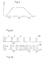
Die Erfindung wird weiter anhand eines Ausführungsbeispieles beschrieben. Es zeigt
- Fig. 1a
- eine schematische Darstellung einer Webmaschine mit eine Blockschaltbild einer Kontrollvorrichtung;
- Fig. 1b
- eine schematische Darstellung einer Webmaschine mit eine Blockschaltbild einer weiteren Ausführungsform einer Kontrollvorrichtung;
- Fig. 2a-2d
- ein künstliches Winkelsignal mit Zusatzinformation;
- Fig. 3
- den zeitlichen Verlauf einer vorgegebenen Winkelgeschwindigkeit;
- Fig. 4a, 4b
- ein künstliches Winkelsignal.
- Fig. 1a
- a schematic representation of a weaving machine with a block diagram of a control device;
- Fig. 1b
- a schematic representation of a weaving machine with a block diagram of a further embodiment of a control device;
- 2a-2d
- an artificial angle signal with additional information;
- Fig. 3
- the time course of a predetermined angular velocity;
- 4a, 4b
- an artificial angle signal.
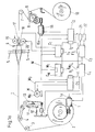
Die Webmaschine gemäss Fig. 1a weist eine übergeordnete
Kontrollvorrichtung CM auf sowie eine Mehrzahl von
untergeordneten Kontrollvorrichtungen C1, C2, C3, C4 und
C5. Die Kontrollvorrichtungen C1, C2, C3, C4, C5, CM
weisen je einen Computer auf und sind über jeweils eine
Kommunikationsvorrichtung F1, F2, F3, F4, F5, FM an einen
gemeinsamen Datenbus L angeschlossen, welcher zur
Übertragung von Daten dient. Ein Winkelgenerator W1
erzeugt ein Winkelsignal W2, welches über eine weitere,
unabhängige Datenleitung W den Kontrollvorrichtungen C1,
C2, C3, C4, C5, CM zugeführt wird. Der Winkelgenerator W1
kann wie in Fig. 1 dargestellt ein Bestandteil der
übergeordneten Kontrollvorrichtung CM bilden, oder auch
als eigenständige Einheit ausgestaltet sein, die in
diesem Fall ebenfalls eine Kommunikationsvorrichtung
aufweisen würde und mit dem gemeinsamen Datenbus L
verbunden wäre, um insbesondere mit der übergeordneten
Kontrollvorrichtung CM zu kommunizieren. Die
Kontrollvorrichtung C5 ist an die Datenleitung W
angeschlossen und empfängt darüber das Winkelsignal W2.
Über den Datenbus L empfängt die Kontrollvorrichtung C5
weitere Steuerbefehle von der übergeordneten
Kontrollvorrichtung CM. Die Kontrollvorrichtung C5 regelt
den Hauptantrieb M der Webmaschine, und überwacht den
Drehwinkel der Hauptwelle mit einem Drehwinkelsensor Ma.
Die Kontrollvorrichtung C4 ist wiederum mit der
Datenleitung W sowie dem Datenbus L verbunden und treibt
über einen Antrieb 1 den Kettbaum 2 an. Zudem erfasst die
Kontrollvorrichtung C4 mit einem Drehwinkelsensor 1a den
Drehwinkel des Antriebes 1 sowie mit einem Sensor 14 die
Spannung der Kettfäden T. Ausgehend vom Kettbaum 2
verlaufen die Kettfäden T über eine Umlenkrolle 3, eine
Spannungsrolle 4, welche eine Spannvorrichtung 11 mit
Federelement 12 sowie eine Auslenkvorrichtung 13 mit
Sensor 14 umfasst, und weiter über den Schaft 5, die
Warenabzugsvorrichtung 7,8,9 zum Warenbaum 10. Die
Kontrollvorrichtung C2 treibt über einen Antrieb 15 die
Warenabzugsvorrichtung 8 an. Zugleich überwacht die
Kontrollvorrichtung C2 mit einem Drehwinkelsensor 15a den
Antrieb 15. Die Schusseintragsdüsen 17,18 ziehen einen
Schussfaden von einer Schussfadenmessvorrichtung 19, 20
ab, wobei diese von der Kontrollvorrichtung C1
angesteuert werden. Der Luftdruck sowie der
Einschaltzeitpunkt der Fluiddüsen 17,18 wird durch die
Kontrollvorrichtung C3 vorgegeben. The weaving machine according to FIG. 1a has a higher-level one
Control device CM and a plurality of
subordinate control devices C1, C2, C3, C4 and
C5. The control devices C1, C2, C3, C4, C5, CM
each have a computer and are each one
Communication device F1, F2, F3, F4, F5, FM to one
common data bus L connected, which for
Serves to transfer data. An angle generator W1
generates an angle signal W2, which is transmitted via a further
independent data line W the control devices C1,
C2, C3, C4, C5, CM is supplied. The angle generator W1
can be part of the
parent control device CM form, or also
be designed as an independent unit, which in
in this case also a communication device
would have and with the common data bus L
would be associated, in particular, with the parent
Control device CM to communicate. The
Control device C5 is connected to the data line W.
connected and receives the angle signal W2.
The control device C5 receives via the data bus L.
further control commands from the parent
Control device CM. The control device C5 regulates
the main drive M of the weaving machine, and monitors the
Rotation angle of the main shaft with a rotation angle sensor Ma.
The control device C4 is in turn with the
Data line W and the data bus L connected and drives
via a
Die übergeordnete Kontrollvorrichtung CM steuert und
überwacht die gesamte Webmaschine mit allen Antrieben
1,15,19,20,M und weiteren Aggregaten 19,20,21,22. Die
Kontrollvorrichtung CM gibt dem Winkelgenerator W1 eine
Winkelgeschwindigkeit vor, welcher daraus ein
entsprechendes Winkelsignal W2 erzeugt, das jeder
Kontrollvorrichtung C1, C2, C3, C4, C5 über die
gemeinsame Datenleitung W zugeführt wird. Eine solche
gemeinsame Datenleitung W wird auch als ein Taktbus
bezeichnet. Diese Datenleitung W bildet zusammen mit dem
Winkelgenerator W1 eine sogenannte synthetische
Leitwelle, weil das entsprechende Winkelsignal W2 den
Drehwinkel festlegt, gemäss dem sich alle Antriebe und
Aggregate ausrichten. Der Drehwinkel wird nicht mehr, wie
bisher aus dem Stand der Technik bekannt, durch die Lage
der Hauptwelle bestimmt, sondern alle Antriebe,
eingeschlossen der Antrieb M der Hauptwelle, folgen dem
durch den Winkelgenerator W1 vorgegebenen Drehwinkel.
Weiter tauscht die Kontrollvorrichtung CM über den
gemeinsamen Datenbus L Daten wie zum Beispiel
Steuerbefehle oder der Status von Aggregaten mit den
untergeordneten Kontrollvorrichtungen C1, C2, C3, C4, C5
aus.The higher-level control device CM controls and
monitors the entire weaving machine with all
Das künstliche Winkelsignal W2 ist ein elektronisch oder optisch übertragenes Signal, dessen zeitlicher Verlauf sich durch eine Vielzahl von Möglichkeiten ausgestalten lässt. In Fig. 4a ist ein Beispiel eines zeitlichen Verlaufes des künstlichen Winkelsignales W2 dargestellt. Das Signal besteht aus einzelnen, rechteckigen Pulsen P, die in zeitlichen Abständen erfolgen. Das Signal ist derart definiert, dass 2048 Pulse P einer Umdrehung um 360 Grad entsprechen. Im vorliegenden Beispiel bezieht sich die Umdrehung um 360 Grad auf die Hauptwelle der Webmaschine. Mit jedem Puls P wird die Hauptwelle durch den Antrieb M um den Winkel (360 Grad / 2048) weiter gedreht. Je mehr Pulse P pro Zeiteinheit auftreten, um so höher ist die Winkelgeschwindigkeit der Hauptwelle. Die Zeit Δt zwischen den einzelnen Pulsen P bestimmt somit die Winkelgeschwindigkeit. Fig. 4b zeigt den Verlauf eines künstlichen Winkelsignals W2, das in einem ersten Zeitbereich T1 eine Erhöhung der Winkelgeschwindigkeit aufweist, in einem zweiten Zeitbereich T2 eine konstante Winkelgeschwindigkeit aufweist, und in einem dritten Zeitbereich T3 eine Reduzierung der Winkelgeschwindigkeit aufweist. Alle Kontrollvorrichtungen C1, C2, C3, C4, C5, CM treiben die kontrollierten Antriebe dem Winkelsignal W2 folgend entsprechend an. Fig. 3 zeigt ein Beispiel einer Ansteuerung der Webmaschine. Das künstliche Winkelsignals W2 wird derart moduliert, dass sich in einem ersten Zeitbereich T1, ausgehend vom Stillstand der Webmaschine, eine rampenförmige Zunahme der Winkelgeschwindigkeit ω ergibt, in einem zweiten Zeitbereich T2 eine konstante Winkelgeschwindigkeit ω ergibt, und in einem dritten Zeitbereich T3 eine rampenförmige Abnahme der Winkelgeschwindigkeit ω ergibt.The artificial angle signal W2 is an electronic or optically transmitted signal, its temporal course shape yourself through a multitude of possibilities leaves. 4a is an example of a temporal The course of the artificial angle signal W2 is shown. The signal consists of individual, rectangular pulses P, that take place at intervals. The signal is defined such that 2048 pulses P of one revolution Correspond to 360 degrees. In the present example the rotation by 360 degrees on the main shaft of the Weaving machine. With every pulse P, the main shaft goes through the drive M by the angle (360 degrees / 2048) turned. The more pulses P occur per unit of time, the more the angular velocity of the main shaft is higher. The Time Δt between the individual pulses P thus determines the angular velocity. 4b shows the course an artificial angle signal W2, which in a first Time range T1 an increase in angular velocity has a constant in a second time period T2 Has angular velocity, and in a third Time range T3 a reduction in the angular velocity having. All control devices C1, C2, C3, C4, C5, CM drive the controlled drives to the angle signal W2 following accordingly. 3 shows an example a control of the weaving machine. The artificial Angle signal W2 is modulated such that in a first time period T1, starting from the standstill of the Loom, a ramped increase in Angular velocity ω results in a second Time range T2 a constant angular velocity ω results, and in a third time period T3 ramped decrease in angular velocity ω results.
Das Abbremsen der Webmaschine im dritten Zeitbereich T3 kann auch derart erfolgen, dass die Webmaschine in einer genau definierten Lage zum Stillstand kommt.Braking the weaving machine in the third time period T3 can also be done in such a way that the loom in one precisely defined location comes to a standstill.
Auf die einzelnen, in Fig. 4a dargestellten Pulse P des Winkelsignals W2 können weiteren Zusatzinformationen aufmoduliert werden. Die Fig. 2a bis 2d zeigen jeweils einen solchen einzelnen Puls P mit einer Zusatzinformation. Die Signalfolge P1, die gesamthaft einen Puls P bildet, bestimmt, dass die Rotation in Uhrzeigerrichtung erfolgt. Die Signalfolge P2 bestimmt, dass die Rotation in Gegenuhrzeigerrichtung erfolgt. Um Antriebe oder Aggregate genau zu positionieren sind die Zusatzinformationen gemäss Fig. 2c und Fig. 2d vorgesehen. Die Signalfolge P3 besagt, dass ein Durchgang bei 0 Grad stattfinden, z.B. bezogen auf die Hauptwelle, wobei die Rotation im Uhrzeigersinn erfolgt. Die Signalfolge P4 besagt, dass ein Durchgang bei 0 Grad stattfindet, wobei die Rotation im Gegenuhrzeigersinn erfolgt.On the individual, shown in Fig. 4a pulses P of Angle signal W2 can provide additional information be modulated. 2a to 2d each show such a single pulse P with a Extra information. The signal sequence P1, the total forms a pulse P, determines that the rotation in Clockwise direction. The signal sequence P2 determines that the rotation is counterclockwise. Around Actuators or units are precisely positioned Additional information according to FIG. 2c and FIG. 2d intended. The signal sequence P3 indicates that one pass take place at 0 degrees, e.g. related to the main shaft, where the rotation is clockwise. The Signal sequence P4 indicates that a pass at 0 degrees takes place, with the rotation counterclockwise he follows.
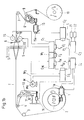
Fig. 1b zeigt ein Blockschaltbild einer weiteren Ausführungsform einer Kontrollvorrichtung. Im Vergleich zur Ausführungsform gemäss Fig. 1a ist der Winkelgenerator W1 über eine Kommunikationsvorrichtung F6 direkt mit dem gemeinsamen Datenbus L verbunden. Das Winkelsignal W wird ebenfalls über den gemeinsamen Datenbus L den weiteren Kontrollvorrichtungen C1, C2, C3, C4, C5, CM übermittelt. Da das Winkelsignal W synchron übermittelt werden muss sorgt die übergeordnete Kontrollvorrichtung CM dafür, dass jeweils während einer Zeitperiode, in welcher das Winkelsignal W zu erwarten ist, der Datenbus L von keiner Kommunikationsvorrichtung F1, F2, F3, F4, F5, FM für die Übertragung von Daten benutzt wird, sodass der Datenbus L frei ist für die Übertragung des Winkelsignals W. Der Winkelgenerator W1 wird durch die übergeordnete Kontrollvorrichtung CM angesteuert, welche über den gemeinsamen Datenbus L miteinander verbunden sind.1b shows a block diagram of another Embodiment of a control device. Compared to the embodiment according to FIG Angle generator W1 via a communication device F6 directly connected to the common data bus L. The Angle signal W is also common Data bus L to the other control devices C1, C2, C3, C4, C5, CM transmitted. Since the angle signal W is synchronous the parent has to be transmitted Control device CM for that during each Time period in which the angle signal W is to be expected the data bus L from no communication device F1, F2, F3, F4, F5, FM for the transmission of data is used so that the data bus L is free for the Transmission of the angle signal W. The angle generator W1 is controlled by the higher-level control device CM controlled, which via the common data bus L are interconnected.
Im Ausführungsbeispiel gemäss Fig. 1b wird der Drehwinkel
der Hauptwelle der Webmaschine mit einem Drehwinkelsensor
Ma erfasst und dieses Winkelsignal W3 der übergeordneten
Kontrollvorrichtung CM zugeführt. Die Kontrollvorrichtung
CM weist eine Umschaltvorrichtung auf, welche entweder
das aktuelle Winkelsignal W3 oder das durch den
Winkelgenerator W1 künstlich erzeugte Winkelsignal W2 dem
Datenbus L übermittelt. Diese Umschaltvorrichtung weist
den Vorteil auf, dass zum Beispiel beim Anfahren oder
Abbremsen der Webmaschine das aktuelle Winkelsignal W3
den Kontrollvorrichtungen C1, C2, C3, C4, C5 vorgebbar
ist. Die Hauptwelle einer Webmaschine kann auf Grund
deren Massenträgheit zum Beispiel während dem Abbremsen
ein Winkelsignal W3 erzeugen, das vom künstlich erzeugten
Winkelsignal W3 abweicht. Durch die Vorgabe des aktuellen
Winkelsignals W3 während zum Beispiel dem Abbremsen
drehen die Antriebe 1,15,19,20 sowie die weiteren
Aggregate 19,20,21,22 synchron zur Hauptwelle.In the exemplary embodiment according to FIG. 1b, the angle of rotation
the main shaft of the loom with a rotation angle sensor
Ma detected and this angle signal W3 of the parent
Control device CM supplied. The control device
CM has a switching device, which either
the current angle signal W3 or by the
Angle generator W1 artificially generated angle signal W2
Data bus L transmitted. This switching device has
the advantage that, for example, when starting off or
Braking the weaving machine the current angle signal W3
the control devices C1, C2, C3, C4, C5 can be specified
is. The main shaft of a weaving machine can be aground
their inertia, for example, during braking
generate an angle signal W3 by the artificially generated
Angle signal W3 deviates. By specifying the current
Angle signal W3 during braking, for example
turn the
Die Umschaltvorrichtung kann ein Bestandteil der übergeordneten Kontrollvorrichtung CM bilden und derart wirken, dass, gemäss dem Ausführungsbeispiel von Fig. 1a, der Winkelgenerator W1 entweder das künstlich erzeugte Winkelsignal W2 oder das gemessene Winkelsignal W3 an die separate Datenleitung W abgibt. In dieser Ausführungsform wird somit entweder das gemessene Winkelsignal W3 oder das künstlich erzeugte Winkelsingal W2 über die separate Datenleitung W übertragen.The switching device can be part of the parent control device CM form and such act that, according to the embodiment of Fig. 1a, the angle generator W1 either the artificially generated Angle signal W2 or the measured angle signal W3 to the outputs separate data line W. In this embodiment is either the measured angle signal W3 or the artificially generated angle signal W2 on the separate Transfer data line W.
Das erfindungsgemässe Verfahren sowie die erfindungsgemässe Vorrichtung eignet sich für verschiedene Arten von Webmaschinen, so zum Beispiel für Luft-, Projektil-, Greifer- oder Reihenfachwebmaschinen.The inventive method and the The device according to the invention is suitable for different types of weaving machines, for example for Air, projectile, rapier or row shed weaving machines.
Claims (12)
- Method for operating a weaving machine having a plurality of control devices (C1, C2, C3, C4, C5, CM) with each control device (C1, C2, C3, C4, C5, CM) controlling and/or monitoring drives (1, 15, M) or further individual units (19, 20, 21, 22) and wherein a common signal (W2) representing the angular position is applied to each control device (C1, C2, C3, C4, C5, CM) and serves to synchronize the drives (1, 15, M) and units (19, 20, 21, 22), characterized in that the signal (W2) representing the angular position is artificially produced by means of a generator (W1) for generating a signal representing the angular position of the weaving machine.
- Method in accordance with claim 1, characterized in that the generator (W1) for generating a signal representing the angular position of the weaving machine is controlled by a master control device (CM).
- Method in accordance with one of the claims 1 or 2, characterized in that each drive (1, 15, M) is operated synchronously to the signal (W2) representing the angular position.
- Method in accordance with one of the claims 1 to 3, characterized in that a signal (W3) representing the angular position of the weaving machine, preferably that of the main shaft, is measured with a sensor (Ma) for angular position measurement and in that, depending on the operational state of the weaving machine, either the signal (W3) representing the angular position or the artificial signal produced by the generator (W1) is used as the signal (W2) representing the angular position.
- Method in accordance with claim 4, characterized in that, during start-up and/or braking of the weaving machine, the measured signal (W3) representing the angular position is used as the signal (W2) representing the angular position.
- Method in accordance with one of the claims 1 to 5, characterized in that additional information such as the rotational direction and the transition through zero is superimposed by modulation onto the signal (W2) representing the angular position.
- Apparatus for operating a weaving machine comprising a plurality of control devices (C1, C2, C3, C4, C5, CM) with the control devices (C1, C2, C3, C4, C5, CM) controlling and/or monitoring drives (1, 15, M) and further individual devices (19, 20, 21, 22) and wherein each control device (CM, C1, C2, C3, C4, C5) is connected to a common data bus (L) for data transmission, characterized in that the apparatus for operating the weaving machine comprises a generator (W1) for producing an artificial signal (W2) representing the angular position and in that the signal (W2) representing the angular position is transmissible to the control devices (CM, C1, C2, C3, C4, C5) via the common data bus (L) or via a separate data bus (W) dedicated to transmitting the signal (W2) representing the angular position.
- Apparatus in accordance with claim 7, characterized in that the generator (W1) for generating a signal representing the angular position of the weaving machine is controllable from a master control device (CM).
- Apparatus in accordance with one of the claims 7 or 8, characterized in that the generator (W1) for generating a signal representing the angular position of the weaving machine is a part of the master control device (CM).
- Apparatus in accordance with one of the claims 7 to 9, characterized in that a sensor (Ma) for angular position measurement is provided in order to detect a rotational signal representing the angular position (W3) of the weaving machine and in that a switching unit is provided, which is preferably arranged in the master control device (CM), in order to apply either the signal from the generator (W1) or the measured rotational signal (W3) as the signal (W2) representing the angular position.
- Apparatus in accordance with one of the claims 7 to 10, characterized in that each control device (CM, C1, C2, C3, C4, C5) comprises a computer as well as a communication device (FM, F1, F2, F3, F4, F5) for data transmission.
- Weaving machine having an apparatus in accordance with one of the claims 7 to 11.
Priority Applications (4)
| Application Number | Priority Date | Filing Date | Title |
|---|---|---|---|
| EP95810085A EP0726344B1 (en) | 1995-02-09 | 1995-02-09 | Process and device for operating a loom |
| DE59506530T DE59506530D1 (en) | 1995-02-09 | 1995-02-09 | Method and device for operating a weaving machine |
| JP7333730A JPH08260300A (en) | 1995-02-09 | 1995-12-21 | Method and apparatus for operating loom |
| US08/595,604 US5613525A (en) | 1995-02-09 | 1996-02-02 | Method and apparatus for generating an artificial angular shaft position to operate a weaving machine |
Applications Claiming Priority (1)
| Application Number | Priority Date | Filing Date | Title |
|---|---|---|---|
| EP95810085A EP0726344B1 (en) | 1995-02-09 | 1995-02-09 | Process and device for operating a loom |
Publications (2)
| Publication Number | Publication Date |
|---|---|
| EP0726344A1 EP0726344A1 (en) | 1996-08-14 |
| EP0726344B1 true EP0726344B1 (en) | 1999-08-04 |
Family
ID=8221699
Family Applications (1)
| Application Number | Title | Priority Date | Filing Date |
|---|---|---|---|
| EP95810085A Expired - Lifetime EP0726344B1 (en) | 1995-02-09 | 1995-02-09 | Process and device for operating a loom |
Country Status (4)
| Country | Link |
|---|---|
| US (1) | US5613525A (en) |
| EP (1) | EP0726344B1 (en) |
| JP (1) | JPH08260300A (en) |
| DE (1) | DE59506530D1 (en) |
Cited By (1)
| Publication number | Priority date | Publication date | Assignee | Title |
|---|---|---|---|---|
| EP1620588B2 (en) † | 2003-04-17 | 2016-10-05 | Picanol | Method for operating a loom |
Families Citing this family (4)
| Publication number | Priority date | Publication date | Assignee | Title |
|---|---|---|---|---|
| DE59607360D1 (en) * | 1996-04-04 | 2001-08-30 | Sulzer Textil Ag Rueti | Jacquard weaving machine and method for operating the same |
| DE102005023929B3 (en) * | 2005-05-24 | 2006-09-14 | Lindauer Dornier Gesellschaft Mit Beschränkter Haftung | Projectile loom, with a projectile to carry a weft yarn length through the shed, is operated at a slow speed for the first weaving cycle on starting and then accelerated to the normal working speed level |
| DE102007012773A1 (en) * | 2007-03-16 | 2008-09-18 | Abb Ag | Electronic cam switching device |
| US9606102B2 (en) | 2013-01-26 | 2017-03-28 | Denovo Sciences, Inc. | System and method for capturing and analyzing cells |
Family Cites Families (8)
| Publication number | Priority date | Publication date | Assignee | Title |
|---|---|---|---|---|
| JPS5593849A (en) * | 1978-12-30 | 1980-07-16 | Toyoda Automatic Loom Works | Timing setting method and apparatus in loom |
| BE889254A (en) * | 1981-06-17 | 1981-12-17 | Picanol Nv | Device for controlling nozzles and other parts of an air loom |
| DE3411651C1 (en) * | 1984-03-29 | 1989-04-27 | bso Steuerungstechnik GmbH, 6603 Sulzbach | Control arrangement for the synchronization of several drives |
| SE8900537D0 (en) * | 1989-02-16 | 1989-02-16 | Iro Ab | guide device |
| US5276627A (en) * | 1989-06-21 | 1994-01-04 | Kabushiki Kaisha Toyoda Jidoshokki Seisakusho | Method of setting weaving conditions for a jet loom |
| JPH05165508A (en) * | 1991-12-12 | 1993-07-02 | Toyota Autom Loom Works Ltd | Weaving machine control method utilizing external storage medium |
| JP2982446B2 (en) * | 1991-12-12 | 1999-11-22 | 株式会社豊田自動織機製作所 | Loom control method |
| DE4215691C2 (en) * | 1992-05-13 | 1996-07-25 | Mayer Textilmaschf | Warp knitting machine |
-
1995
- 1995-02-09 DE DE59506530T patent/DE59506530D1/en not_active Expired - Fee Related
- 1995-02-09 EP EP95810085A patent/EP0726344B1/en not_active Expired - Lifetime
- 1995-12-21 JP JP7333730A patent/JPH08260300A/en active Pending
-
1996
- 1996-02-02 US US08/595,604 patent/US5613525A/en not_active Expired - Fee Related
Cited By (1)
| Publication number | Priority date | Publication date | Assignee | Title |
|---|---|---|---|---|
| EP1620588B2 (en) † | 2003-04-17 | 2016-10-05 | Picanol | Method for operating a loom |
Also Published As
| Publication number | Publication date |
|---|---|
| DE59506530D1 (en) | 1999-09-09 |
| EP0726344A1 (en) | 1996-08-14 |
| US5613525A (en) | 1997-03-25 |
| JPH08260300A (en) | 1996-10-08 |
Similar Documents
| Publication | Publication Date | Title |
|---|---|---|
| EP0350446B1 (en) | Terry fabric making process and loom with pile-forming devices | |
| DE3423829C2 (en) | Rotary drive device for a measuring and storage device for the weft thread of a shuttleless loom | |
| DE2854257C2 (en) | Textile machine | |
| EP0726344B1 (en) | Process and device for operating a loom | |
| DE19918995A1 (en) | Steering and braking system for a vehicle | |
| DE69926980T2 (en) | Method and device for synchronization control | |
| DE4215691C2 (en) | Warp knitting machine | |
| DE19626821A1 (en) | Modular rotary screen printing machine | |
| EP1620588A1 (en) | Method for operating a loom | |
| DE4410062C2 (en) | Device for controlling a drive | |
| EP0965165B1 (en) | Method and device for maintaining the perfect synchronism of individual, networked drives of a decentralized drive system | |
| EP0523581A1 (en) | Loom and process for operating a loom | |
| EP0799920A1 (en) | Jacquard loom and method of operating said loom | |
| EP0893525A1 (en) | Driving arrangement for a loom and loom with such an arrangement | |
| CH653061A5 (en) | WEAVING MACHINE WITH REMOVAL OF THE SPINE FROM FIXED REELS. | |
| DE10259494A1 (en) | Method for control of separately driven sub-systems of a print machine, involves synchronizing movement curves of the two systems are synchronized to minimize vibration differences between them | |
| DE3520244A1 (en) | Fabric draw-off device on a weaving machine | |
| EP0602383B1 (en) | Electronic control device for machines, particularly for textile machines | |
| DE10125608B4 (en) | Encoder signal converter for machine tools and production machines, as well as robots | |
| DE19704702B4 (en) | Elimination of loose effects in printing presses | |
| EP0591627A1 (en) | Process to avoid streaks produced by misspicks and loom for implementing such method | |
| DE2527182A1 (en) | REMOTE CONTROL DEVICE | |
| DE2148443B2 (en) | Speed-dependent, automatic, electrical switching device for gearboxes with synchronization device | |
| DE102004045208A1 (en) | loom | |
| EP0521244B1 (en) | Weaving loom |
Legal Events
| Date | Code | Title | Description |
|---|---|---|---|
| PUAI | Public reference made under article 153(3) epc to a published international application that has entered the european phase |
Free format text: ORIGINAL CODE: 0009012 |
|
| AK | Designated contracting states |
Kind code of ref document: A1 Designated state(s): BE DE FR GB IT |
|
| RBV | Designated contracting states (corrected) |
Designated state(s): BE DE FR GB IT |
|
| 17P | Request for examination filed |
Effective date: 19961227 |
|
| GRAG | Despatch of communication of intention to grant |
Free format text: ORIGINAL CODE: EPIDOS AGRA |
|
| 17Q | First examination report despatched |
Effective date: 19980908 |
|
| GRAG | Despatch of communication of intention to grant |
Free format text: ORIGINAL CODE: EPIDOS AGRA |
|
| GRAH | Despatch of communication of intention to grant a patent |
Free format text: ORIGINAL CODE: EPIDOS IGRA |
|
| GRAH | Despatch of communication of intention to grant a patent |
Free format text: ORIGINAL CODE: EPIDOS IGRA |
|
| GRAA | (expected) grant |
Free format text: ORIGINAL CODE: 0009210 |
|
| AK | Designated contracting states |
Kind code of ref document: B1 Designated state(s): BE DE FR GB IT |
|
| PG25 | Lapsed in a contracting state [announced via postgrant information from national office to epo] |
Ref country code: GB Free format text: LAPSE BECAUSE OF FAILURE TO SUBMIT A TRANSLATION OF THE DESCRIPTION OR TO PAY THE FEE WITHIN THE PRESCRIBED TIME-LIMIT Effective date: 19990804 Ref country code: FR Free format text: LAPSE BECAUSE OF FAILURE TO SUBMIT A TRANSLATION OF THE DESCRIPTION OR TO PAY THE FEE WITHIN THE PRESCRIBED TIME-LIMIT Effective date: 19990804 |
|
| REF | Corresponds to: |
Ref document number: 59506530 Country of ref document: DE Date of ref document: 19990909 |
|
| ITF | It: translation for a ep patent filed |
Owner name: ING. ZINI MARANESI & C. S.R.L. |
|
| EN | Fr: translation not filed | ||
| GBV | Gb: ep patent (uk) treated as always having been void in accordance with gb section 77(7)/1977 [no translation filed] |
Effective date: 19990804 |
|
| PLBE | No opposition filed within time limit |
Free format text: ORIGINAL CODE: 0009261 |
|
| STAA | Information on the status of an ep patent application or granted ep patent |
Free format text: STATUS: NO OPPOSITION FILED WITHIN TIME LIMIT |
|
| 26N | No opposition filed | ||
| PG25 | Lapsed in a contracting state [announced via postgrant information from national office to epo] |
Ref country code: IT Free format text: LAPSE BECAUSE OF NON-PAYMENT OF DUE FEES;WARNING: LAPSES OF ITALIAN PATENTS WITH EFFECTIVE DATE BEFORE 2007 MAY HAVE OCCURRED AT ANY TIME BEFORE 2007. THE CORRECT EFFECTIVE DATE MAY BE DIFFERENT FROM THE ONE RECORDED. Effective date: 20050209 |
|
| PGFP | Annual fee paid to national office [announced via postgrant information from national office to epo] |
Ref country code: DE Payment date: 20080219 Year of fee payment: 14 |
|
| PGFP | Annual fee paid to national office [announced via postgrant information from national office to epo] |
Ref country code: BE Payment date: 20080327 Year of fee payment: 14 |
|
| BERE | Be: lapsed |
Owner name: *SULZER RUTI A.G. Effective date: 20090228 |
|
| PG25 | Lapsed in a contracting state [announced via postgrant information from national office to epo] |
Ref country code: DE Free format text: LAPSE BECAUSE OF NON-PAYMENT OF DUE FEES Effective date: 20090901 |
|
| PG25 | Lapsed in a contracting state [announced via postgrant information from national office to epo] |
Ref country code: BE Free format text: LAPSE BECAUSE OF NON-PAYMENT OF DUE FEES Effective date: 20090228 |