EP0591627A1 - Process to avoid streaks produced by misspicks and loom for implementing such method - Google Patents
Process to avoid streaks produced by misspicks and loom for implementing such method Download PDFInfo
- Publication number
- EP0591627A1 EP0591627A1 EP93110910A EP93110910A EP0591627A1 EP 0591627 A1 EP0591627 A1 EP 0591627A1 EP 93110910 A EP93110910 A EP 93110910A EP 93110910 A EP93110910 A EP 93110910A EP 0591627 A1 EP0591627 A1 EP 0591627A1
- Authority
- EP
- European Patent Office
- Prior art keywords
- shaft
- reed
- dobby
- loom
- gear
- Prior art date
- Legal status (The legal status is an assumption and is not a legal conclusion. Google has not performed a legal analysis and makes no representation as to the accuracy of the status listed.)
- Withdrawn
Links
Images

Classifications
-
- D—TEXTILES; PAPER
- D03—WEAVING
- D03C—SHEDDING MECHANISMS; PATTERN CARDS OR CHAINS; PUNCHING OF CARDS; DESIGNING PATTERNS
- D03C1/00—Dobbies
- D03C1/14—Features common to dobbies of different types
- D03C1/16—Arrangements of dobby in relation to loom
-
- D—TEXTILES; PAPER
- D03—WEAVING
- D03D—WOVEN FABRICS; METHODS OF WEAVING; LOOMS
- D03D51/00—Driving, starting, or stopping arrangements; Automatic stop motions
- D03D51/002—Avoiding starting marks
-
- D—TEXTILES; PAPER
- D03—WEAVING
- D03D—WOVEN FABRICS; METHODS OF WEAVING; LOOMS
- D03D51/00—Driving, starting, or stopping arrangements; Automatic stop motions
- D03D51/06—Driving, starting, or stopping arrangements; Automatic stop motions using particular methods of stopping
- D03D51/08—Driving, starting, or stopping arrangements; Automatic stop motions using particular methods of stopping stopping at definite point in weaving cycle, or moving to such point after stopping
- D03D51/085—Extraction of defective weft
Abstract
Description
Die Erfindung betrifft ein Verfahren zur Vermeidung von schußfehlerbedingten Gewebemarkierungen, die durch einen Webblattanschlag beim Zurückweben entstehen, wonach bei einem Schußfadenbruch ein Webstop ausgelöst wird und der fehlerhafte Schußfaden von den Kettfäden eingebunden und mittels des Webblattes an der Anschlagkante des Gewebes angeschlagen vorliegt, und dabei die motorgetrieben Hauptwelle der Webmaschine, die Webblattwelle und die mit der Hauptwelle über ein getriebliches Mittel gekuppelte Antriebswelle der Schaftmaschine bei einem Drehwinkel von etwa 60 Grad nach dem Webblattanschlag stillsteht, daraufhin vorzugsweise bei gleichzeitigem gesteuertem Zurückdrehen von Kett- und Warenbaum um eine Anzahl von Drehwinkelgraden Herbeiführen einer Fachoffenstellung und Entfernen des fehlerhaften Schußfadens, und schließlich Zurückführen der Webblattwelle und der Schaftmaschinenantriebswelle in die für den Neustart der Webmaschine notwendige Drehwinkelposition.The invention relates to a method for avoiding weft mark-induced fabric markings, which are caused by a reed stop when weaving backwards, after which a weave stop is triggered in the event of a weft break and the faulty weft thread is bound in by the warp threads and struck on the stop edge of the fabric by means of the reed, and in so doing the motor-driven main shaft of the weaving machine, the reed shaft and the drive shaft of the dobby coupled to the main shaft via a gear means at a rotation angle of about 60 degrees after the reed stop, then preferably with simultaneous controlled turning back of the warp and fabric by a number of degrees of rotation bringing about one Shed opening and removal of the defective weft, and finally returning the reed shaft and the dobby drive shaft to the rotational angle position necessary for the restart of the loom.
Eine Unterbrechung des Webprozesses und damit ein Webmaschinenstop ist auf die unterschiedlichsten Ursachen zurückzuführen. So wird eine Unterbrechung des Webprozesses u.a. dann erfolgen, wenn ein fehlerhafter Schußfaden in das Webfach eingetragen und ein Webfachwechsel den Schußfaden in die Kettfäden nach dem Detektieren des Webmaschinenstop einbindet.
Nach einer schußfehlerbedingten Unterbrechung des Webprozesses bleibt die Hauptantriebswelle der Webmaschine bei einem Drehwinkel von ca. 60 Grad nach dem Anschlagen des Schußfadens durch das Webblatt stehen. Der defekte Schußfaden ist an das fertige Gewebe angeschlagen und abgebunden.An interruption in the weaving process and thus a weaving machine stop can be attributed to a wide variety of causes. The interruption of the weaving process will take place, inter alia, when a faulty weft thread is entered into the shed and a change of shed incorporates the weft thread into the warp threads after the loom stop is detected.
After an interruption in the weaving process due to a picking error, the main drive shaft of the weaving machine stops at an angle of rotation of approximately 60 degrees after the weft thread has been picked up by the weaving reed. The defective weft thread is attached to the finished fabric and tied.
Zur Behebung des sogenannten Schußfehlers wird - wie an sich bekannt - das Webfach durch Zurückdrehen von mehr als 60 Drehwinkelgraden der Webmaschinenhauptwelle und durch Zurückdrehen des Schaftantriebes geöffnet. Ist das zuvor geschlossene Webfach wieder geöffnet, wird der angeschlagene defekte Schußfaden vom Gewebe in bekannter Weise entfernt.To remedy the so-called weft error, the shed is opened - as is known per se - by turning back more than 60 degrees of rotation of the main loom shaft and by turning back the shaft drive. If the previously closed shed is opened again, the broken weft thread is removed from the fabric in a known manner.
Nachdem der defekte Schußfaden entnommen wurde, muß die Schaftmaschine bzw. deren Antrieb vor dem erneuten Starten der Webmaschine die Bindung des entnommenen defekten Schußfadens noch einmal Einlesen. Das bedeutet, daß die den Bewegungsablauf der Schaftmaschine steuernden elektronischen und mechanischen Mittel in die Position zurückversetzt werden müssen, die jener vor dem Anschlagen des defekten Schußfadens entspricht.
Bei Webmaschinen, in denen die Webmaschinenhauptwelle gleichzeitig der Antrieb für die Schaftmaschine ist, Webmaschine und Schaftmaschine sind also starr über getriebliche Mittel miteinander gekoppelt, führt das Webblatt beim Auflösen der Bindung daher zwangsläufig ein nochmaliges Anschlagen des an der Gewebekante anliegenden defekten Schußfaden aus, bevor das Webblatt in seine rückwärtige Position schwenkt. Das Webblatt schlägt also zwangsläufig an die Gewebeanschlaglinie an. Dieses Anschlagen führt insbesondere bei Geweben mit "Vortuch" zu unerwünschten und meist erst nach dem Ausrüsten (z.B. Färben, Mercerisieren) des Gewebes, zu sichtbaren Markierungen oder sogenannten Schußstreifen.
Es wurden bisher Bemühungen unternommen, diese Fehlerstellen durch ein Verschieben der Webware bzw. der Gewebeanschlaglinie in Richtung des Warenabzugs zu unterbinden.
Ein diesbezüglicher Lösungsvorschlag ist der DE-OS 41 37 681 zu entnehmen.After the defective weft thread has been removed, the dobby or its drive must read the binding of the removed defective weft thread again before starting the weaving machine again. This means that the electronic and mechanical means controlling the movement of the dobby must be returned to the position which corresponds to that before the defective weft thread was struck.
In looms in which the main loom shaft is at the same time the drive for the dobby, the loom and dobby are therefore rigidly coupled to one another via gear means, the weaving reed therefore inevitably repeats the defective weft thread lying against the fabric edge before the weaving Swivels reed into its rearward position. The reed inevitably strikes the tissue stop line. This striking leads, particularly in the case of fabrics with a “front cloth”, to undesirable and usually only after finishing (for example dyeing, mercerizing) the fabric, to visible markings or so-called weft strips.
Efforts have been made to prevent these defects by moving the woven goods or the fabric stop line in the direction of the goods take-off.
A proposed solution can be found in DE-OS 41 37 681.
In der genannten DE-Offenlegungsschrift wird vorgeschlagen, daß beim Zurückweben, also bei einer Langsam-Rückwärtsdrehung der Webmaschinenhauptwelle bzw. des mit der Hauptwelle verbundenen Webmaschinenmotors, Einrichtungen betrieben werden, die vor dem erneuten Anschlagen des Webblattes den Warenrand des Gewebes und damit die Gewebeanschlagkante um eine bestimmte Wegstrecke in Richtung Warenabzug aus der Normalposition verlagern. Damit soll die Gewebeanschlagkante gegen ein Anschlagen des Webblattes beim Zurückweben geschützt werden.
Nach Beenden des Zurückwebens führen diese Einrichtungen das Gewebe und damit die Gewebeanschlagkante in die Normalposition zurück. Als nachteilig wird bei dieser Verfahrensweise erkannt, daß hierzu ein erheblicher Steuerungstechnischer Aufwand erforderlich ist.In the above-mentioned DE laid-open specification it is proposed that when weaving back, that is, during a slow reverse rotation of the Weaving machine main shaft or the weaving machine motor connected to the main shaft, devices are operated which shift the fabric edge of the fabric and thus the fabric stop edge by a certain distance in the direction of the fabric take-off from the normal position before the weaving reed is struck again. The purpose of this is to protect the fabric stop edge against striking the reed when weaving back.
After the weaving back is finished, these devices return the tissue and thus the tissue stop edge to the normal position. It is recognized as a disadvantage of this procedure that a considerable amount of control engineering is required for this.
Bekannt ist ferner, die Schaftmaschine auf der Antriebsseite von der Webmaschinenhauptwelle nach dem schußfehlerbedingten Webmaschinenstop abzukoppeln. Ein separater, mit der Antriebswelle der Schaftmaschine in Wirkverbindung stehender Antrieb sorgt dann für das Zurückdrehen der Schaftmaschinenantriebswelle und folglich über die Webschäfte für das Auflösen der Bindung des von den Kettfäden eingebundenen defekten Schußfadens, ohne das das Webblatt mitbewegt wird. Es wird also damit das Webfach reproduziert, in welches der defekte Schußfaden eingetragen ist.It is also known to decouple the dobby on the drive side from the main loom shaft after the loom stop caused by picking errors. A separate drive, which is operatively connected to the drive shaft of the dobby, then ensures that the dobby drive shaft is turned back and consequently, via the heald frames, to loosen the binding of the defective weft thread bound by the warp threads, without the reed being moved as well. The shed in which the defective weft thread is entered is thus reproduced.
Nachdem der defekte Schußfaden entfernt ist, wird mittels eines erneuten Webmaschinenstarts der vorangegangene Schußeintrag wiederholt ohne daß zunächst der Schußfaden von dem Webblatt anschlagen wird.After the defective weft has been removed, the previous weft insertion is repeated by means of a renewed weaving machine start without the weft first striking the reed.
Aus der DE-OS 25 09 665 ist eine Webmaschine mit einer Fachbildeeinrichtung, insbesondere Schaftmaschine oder Jacquardmaschine bekannt, bei der die Fachbildeeinrichtung sowie ggf. eine Schußfadenwahleinrichtung bei Webstörungen von der Webmaschinenhauptwelle über eine Hauptwellenkupplung aus- und mit einer Rücklaufeinrichtung einkuppelbar ist, wobei letztere aus einem Rücklaufmotor und einer Rücklaufschaltkupplung besteht.
Bei einer derartigen Webmaschine soll die Rücklaufeinrichtung so gestaltet sein, daß die Behebung einer Webstörung wesentlich weniger Zeit in Anspruch nimmt.
Dazu wird vorgeschlagen, daß die Rücklaufeinrichtung zwischen der Rücklaufschaltkupplung und dem Rücklaufmotor ein an sich bekanntes Schrittgetriebe mit einem im Bereich von Schrittanfang bzw. Schrittende stark erhöhtem Untersetzungsverhältnis aufweist.
Die bekannte Lösung erwähnt nicht, daß das Zurückweben in der Regel mit einem erneuten Anschlagen des Webblattes an die Gewebekante verbunden ist, was zu einer Verdichtung des Gewebes und zu einer sogenannten Streifenbildung im Gewebe führt. Außerdem weist die bekannte Webmaschine für das Zurückweben eine Rücklaufeinrichtung auf, die einen separaten Rücklaufmotor erfordert.From DE-OS 25 09 665 a weaving machine with a shedding device, in particular a dobby or jacquard machine is known, in which the shedding device and possibly a weft selection device in the event of weaving faults can be disengaged from the weaving machine main shaft via a main shaft coupling and can be coupled in with a return device, the latter consisting of a return motor and a reverse clutch.
In such a weaving machine, the return device should be designed in such a way that the removal of a weaving malfunction takes considerably less time.
For this purpose, it is proposed that the return device between the reverse clutch and the reverse motor has a stepping gear known per se with a step-up ratio which is greatly increased in the area of the beginning or end of the step.
The known solution does not mention that the weaving back is usually associated with a renewed striking of the reed against the edge of the fabric, which leads to a densification of the fabric and to a so-called streaking in the fabric. In addition, the known weaving machine for weaving back has a return device that requires a separate return motor.
Bekannt ist gemäß DE-OS 27 06 646 eine technische Lösung für Webmaschinen, welche vorsieht, daß im Falle einer Webstörung die Betriebsbewegung der Weblade in einer Vorhaltestellung beendet wird, aus der heraus die Weblade mit einer gegenüber der Betriebsbewegung langsameren Positionierbewegung in eine gewünschte Stillstandsposition gebracht wird.
Die bekannte Lösung sieht ferner vor, den Langsamantrieb der Weblade durch den Webmaschinen-Antriebsmotor, der als drehzahlveränderlicher Elektromotor ausgebildet sein kann, selbst zu realisieren. Es wird die Möglichkeit erwähnt, daß als Langsamantrieb ein zum Webmaschinen-Antriebsmotor zusätzlicher Motor vorgesehen sein kann, der auch zum Zurückbewegen einer Schaftmaschine, also zum Zurückweben, dient.
Auch diese Lösung erfordert für das Zurückweben der Schaftmaschine neben getrieblichen Mitteln und einer Kupplungseinrichtung zum Trennen und Wiederverbinden des Webmaschinenantriebes von bzw. mit der Schaftmaschine zumindest einen zusätzlichen Rücklaufmotor.According to DE-OS 27 06 646, a technical solution for weaving machines is known which provides that in the event of a weaving malfunction, the operating movement of the sley is terminated in a reserve position from which the sley is brought into a desired standstill position with a slower positioning movement than the operating movement becomes.
The known solution also provides for the slow drive of the sley to be realized by the weaving machine drive motor, which can be designed as a variable-speed electric motor. The possibility is mentioned that an additional to the loom drive motor as a slow drive Motor can be provided, which is also used for moving back a dobby, that is, for weaving back.
This solution also requires at least one additional return motor for the weaving back of the dobby in addition to gear means and a coupling device for disconnecting and reconnecting the loom drive from or to the dobby.
Aufgabe der Erfindung ist es, beim sogenannten Zurückweben, d.h. Auflösen der Bindung eines defekten von den Kettfäden eingebundenen Schußfadens, ein erneutes Anschlagen des Webblattes zu unterbinden und eine Vorrichtung zur Durchführung des Verfahrens anzugeben, die auf einen vom Webmaschinen-Hauptantrieb zusätzlichen motorischen Rücklaufantrieb für die Schaftmaschine verzichtet.The object of the invention is, in so-called backweaving, i.e. Dissolving the binding of a defective weft thread bound by the warp threads, preventing the reed from striking again and specifying a device for carrying out the method which dispenses with a motor-driven return drive for the dobby machine which is additional to the main loom drive.
Erfindungsgemäß wird die Aufgabe dadurch gelöst, daß die Webmaschinenhauptwelle und damit die Webblattwelle und die Antriebswelle der Schaftmaschine nach einem schußfehlerbedingten Webmaschinenstop gemeinsam um eine Anzahl Drehwinkelgrade, die geringer als 360 Drehwinkelgrade der Webmaschinenhauptwelle ist, in der vor dem Webmaschinenstop vorliegenden Drehrichtung weiter gedreht werden. Daraufhin erfolgt ein Entkuppeln des Antriebes der Webmaschinenhauptwelle von der Antriebswelle der Schaftmaschine. Nachfolgend gleichzeitiges Zurückdrehen der Webmaschinenhauptwelle, der Webblattwelle und der Schaftmaschinenantriebswelle, wobei die Webmaschinenhauptwelle um eine Anzahl Drehwinkelgrade, die geringer als 360 Drehwinkelgrade ist, und die Schaftmaschinenantriebswelle über den mechanischen und elektronischen Einlesepunkt, der den Punkt repräsentiert, an welchen die Bindung des vorhergenden Schusses vollzogen wurde, um eine Anzahl Drehwinkelgrade gleich oder größer als 360 zurückgedreht wird.According to the invention the object is achieved in that the weaving machine main shaft and thus the reed shaft and the drive shaft of the dobby are rotated together after a weaving machine stop caused by a weft error by a number of degrees of rotation angle that is less than 360 degrees of rotation angle of the weaving machine main shaft in the direction of rotation before the weaving machine stop. The drive of the main loom shaft is then uncoupled from the drive shaft of the dobby. Subsequent simultaneous turning back of the loom main shaft, the reed shaft and the dobby drive shaft, the loom main shaft being rotated by a number of degrees of rotation angle that is less than 360 degrees of rotation angle, and the dobby machine drive shaft above the mechanical and electronic read-in point, which represents the point at which the binding of the previous weft takes place was turned back by a number of degrees of rotation angle equal to or greater than 360.
Ein derartiger Verfahrensablauf wird vorrichtungsseitig durch ein Getriebe, z.B. ein Schaltgetriebe, möglich das zwischen einem eine Antriebs- und eine Abtriebswelle aufweisenden getrieblichen Mittel für das rechte Greifergetriebe und der Antriebswelle der Schaftmaschine angeordnet ist.Such a process sequence is carried out on the device side by a gear, e.g. a manual transmission, which is arranged between a drive means and an output shaft having gear means for the right gripper gear and the drive shaft of the dobby.
Die Abtriebswelle des getrieblichen Mittels ist dabei mit einem auf ihr axial verschiebbar und drehfest angeordneten Kupplungsteil des Schaltgetriebes ausgerüstet. Das Schaltgetriebe ist so ausgelegt, daß es ein Übersetzungsverhälntis von etwa i = 1:2 bis i = 1:3 ins Schnelle gestattet.
Das bedeutet, daß beim Zurückweben die Schaftmaschinenantriebswelle in der gleichen Zeiteinheit mit einer höheren Winkelgeschwindigkeit zurückgedreht wird als die Webmaschinenhauptwelle. Aufgrund dessen bewegt sich das Webblatt in einem vorgegebenen Bereich zwischen den Blattanschlägen zurück wärend die das Webfach bildenden Webschäfte bzw. die Antriebswelle der Schaftmaschine zu dem Einlesepunkt zurückbewegt werden.
Unter Einlesepunkt ist hier die Drehwinkelstellung zu verstehen, die die Antriebswelle der Schaftmaschine zum Zeitpunkt der Detektierung des Schußfadenbruches einnahm.The output shaft of the gear means is equipped with an axially displaceable and rotationally fixed coupling part of the gearbox. The manual transmission is designed so that it allows a ratio of about i = 1: 2 to i = 1: 3 in a flash.
This means that when weaving back, the dobby drive shaft is rotated back in the same time unit at a higher angular speed than the main loom shaft. Because of this, the reed moves back in a predetermined area between the leaf stops while the heald frames forming the shed or the drive shaft of the dobby are moved back to the reading point.
The read-in point here is to be understood as the angle of rotation position which the drive shaft of the dobby took at the time of detection of the weft break.
Mit dem erfindungsgemäßen Verfahrensablauf und der Vorrichtung zu dessen Durchführung wird erreicht, daß ein Anschlagen des Webblattes während eines schußfehlerbedingten "Zurückwebens" vermieden wird. Markierungen im Gewebe, die auf das Webblattanschlagen beim Zurückweben zurückzuführen sind, werden damit ausgeschlossen.With the process sequence according to the invention and the device for carrying it out, the weaving reed is prevented from striking during a "weaving back" caused by a picking error. Markings in the fabric, which can be attributed to the weaving of the reed when weaving back, are thus excluded.
Die Erfindung soll nachstehend an einem Ausführungsbeispiel näher erläutert werden.
In den dazugehörigen Zeichnungen zeigen:
- Fig. 1
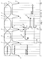
- eine graphische Darstellung des Webblatt-Bewegungsablaufes und der Webfachbildung im Vergleich mit und ohne der erfindungsgemäßen Lösung,
- Fig. 2
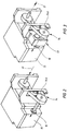
- die Vorrichtung gemäß Prior Art,
- Fig. 3
- das Schaltgetriebe, eingeordnet zwischen Schaftmaschine und getrieblichem Mittel,
- Fig. 4
- das Schaltgetriebe bei Normalbetrieb der Webmaschine,
- Fig. 5
- das Schaltgetriebe beim Zurückweben.
In the accompanying drawings:
- Fig. 1
- a graphical representation of the reed movement and the weaving shed in comparison with and without the solution according to the invention,
- Fig. 2
- the device according to Prior Art,
- Fig. 3
- the manual gearbox, arranged between the dobby and gear means,
- Fig. 4
- the gearbox during normal operation of the weaving machine,
- Fig. 5
- the manual transmission when weaving back.
Es sei zunächst vorausgeschickt, daß im Ausführungsbeispiel die Bewegung der Fachbildeorgane, also der Webmaschinenschäfte, zum Einbinden der Schußfäden in die Kettfäden durch eine Schaftmaschine erfolgt.
Die Bewegung des Webblattes zum Zwecke des Anschlagens des von den Kettfäden eingebundenen Schußfadens erfolgt über die sogenannte Webblattwelle, deren Antrieb von der Webmaschinenhauptwelle abgeleitet ist.
Der Bewegungsablauf der Webschäfte und des Webblattes ist in dem Diagramm gemäß Fig. 1 dargestellt.It should first be stated that in the exemplary embodiment the movement of the shedding organs, that is to say the weaving machine shafts, for incorporating the weft threads into the warp threads is carried out by a dobby.
The movement of the reed for the purpose of striking the weft thread bound by the warp threads takes place via the so-called reed shaft, the drive of which is derived from the main loom shaft.
The sequence of movements of the heald frames and the reed is shown in the diagram according to FIG. 1.
Im Diagramm sind auf der Abszisse die Drehwinkelgrade der Webmaschinenhauptwelle aufgetragen. Danach ist nach jeweils einer vollen Umdrehung der Hauptwelle ein Fachschluß herbeigeführt, d.h. ein in das Webfach eingetragener Schußfaden ist von den die Kettfäden bewegenden Webschäfte eingebunden.
Der Bewegungsablauf der Fachbildeorgane ist mit dem sinusförmigen Verlauf der Linien 1 und 2 über mehrere Schußfadeneinträge dargestellt. Der Schnittpunkt 3 der Linien 1 und 2 ist der Punkt innerhalb eines Webzyklus, in welchem der Fachschluß erfolgt.The degrees of rotation of the main loom shaft are plotted on the abscissa in the diagram. Thereafter, after one full revolution of the main shaft, a shed closure is brought about, ie a weft thread entered in the shed is bound by the heald frames moving the warp threads.
The movement of the shedding organs is shown with the sinusoidal course of
Die unter den Linien 1 und 2 verlaufende Linie 4 zeigt den Bewegungsablauf des Webblattes ebenfalls über mehrere Schußfadeneinträge. Auch hier erfolgt nach jeweils einer vollen Umdrehung der Webmaschinenhauptwelle bzw. der Webblattwelle ein Anschlagen des zuvor eingebundenen Schußfadens durch das Webblatt.
Wenn der Punkt 5 im Bewegungsablauf des Webblattes erreicht ist, ist der bei Schnittpunkt 3 eingebundene Schußfaden an das Tuch angeschlagen.
Es sei noch daraufhingewiesen, daß - wie aus den beiden Bewegungsabläufen zu erkennen - selbstverständlich der Fachschluß in Schnittpunkt 3 einige Hauptwellen-Drehwinkelgrade vor dem Webblattanschlag im Punkt 5 erfolgt.
Bei einem sogenannten Schußfadenbruch wird bekanntlich die Webmaschine automatisch abgestellt. So sei z.B. in Punkt 6 der sinusförmig verlaufenden Linie 1 und 2 ein Schußfadenbruch detektiert. Die Detektierung führt zum Stop des Webprozesses.
Die Massenträgheitsmomente des Webmaschinenantriebes und die mit dem Antrieb in Verbindung stehenden Fachbildeorgane führen jedoch dazu, daß die Webmaschinenhauptwelle erst im Punkt 7, also ca. 60 Winkelgrade nach dem Webblattanschlag zum Stillstand kommen. Der defekte Schußfaden ist also von den Fachbildeorganen abgebunden und mittels des Webblattes an das Tuch angeschlagen.Line 4 running under
When
It should also be pointed out that - as can be seen from the two movement sequences - of course, the technical conclusion in
As is known, the weaving machine is automatically switched off in the event of a so-called weft break. For example,
However, the moments of inertia of the loom drive and the shedding organs connected to the drive mean that the main loom shaft only comes to a standstill at point 7, i.e. about 60 degrees after the reed stop. The defective weft thread is therefore tied off by the specialist organs and attached to the cloth by means of the reed.
Um den defekten Schußfaden automatisch von dem Tuch zu entfernen, ist ein sogenanntes Zurückweben notwendig. Ein Zurückweben bedeutet, daß die Webmaschinenhauptwelle und damit die Webblattwelle und die Schaftmaschinenantriebswelle langsam von dem Punkt 7 über Punkt 5 bis zu Punkt 6 zurückbewegt werden. Das Zurückweben erfolgt gemäß dem vereinfacht durch die Pfeile 8,9 für die Schaftmaschinenantriebswelle und für die Webblattwelle dargestellten Bewegungsablauf.In order to automatically remove the defective weft thread from the cloth, a so-called back weaving is necessary. Weaving back means that the main loom shaft and thus the reed shaft and the dobby drive shaft are slowly moved back from point 7 to
Es ist erkennbar, daß hierbei der Bewegungsablauf 4 des Webblattes ein erneutes Anschlagen des defekten Schußfadens in Punkt 5 einschließt bevor das Webfach zum Entfernen des defekten Schußfadens geöffnet ist. Dieses erneute Anschlagen des defekten Schußfadens führt, wie eingangs schon erwähnt, zu einem unerwünschten Verdichten des Gewebes in Bezug auf die nachfolgende Gewebebildung und zu einer sichtbaren Streifenbildung, vornehmlich nach dem Ausrüsten des Gewebes.It can be seen that the movement sequence 4 of the reed includes a new striking of the defective weft thread in
Der erfindungsgemäße Bewegungsablauf der Webmaschinenhauptwelle und der von der Hauptwelle abgeleitete Bewegungsablauf der Webblattwelle und des Schaftmaschinenantriebs erfolgt gemäß der Pfeile 10 und 11 in Fig.1. Hier wird ein erneutes Anschlagen des defekten Schußfadens beim Zurückweben durch das Webblatt dadurch vermieden, indem die Webmaschinenhauptwelle bzw. die von der Hauptwelle abgeleiteten Antriebe der Schaftmaschine und des Webblattes nach dem Webstop um eine Anzahl Drehwinkelgrade, die kleiner als 360 ist, in eine Drehrichtung z.B. bis Punkt 12 - siehe auch Richtungspfeile 10,11 - langsam weitergedreht wird, die sie vor dem Webstop inne hatten.
Bei Punkt 12 erfolgt ein Entkuppeln der Verbindung zwischen der Schaftmaschinenantriebswelle und der Webmaschinenhauptwelle bei gleichzeitigem Übergang in eine Zahnradübersetzung für die Antriebswelle der Schaftmaschine und Drehen der Webblatt- und Schaftmaschinenantriebswellen in die der vorangegangenen Drehrichtung entgegengesetzte Drehrichtung. Dabei ist die Anzahl der Drehwinkelgrade der Webmaschinenhauptwelle kleiner als 360 und die Anzahl der Drehwinkelgrade der Schaftmaschinenantriebswelle größer als 360. Aufgrund des Übersetzungsverhältnisses von etwa i = 1:2 bis i = 1:3 kann die Schaftmaschinenantriebswelle mit einer höheren Winkelgeschwindigkeit pro Zeiteinheit zurückgedreht werden als die Webmaschinenhauptwelle. Vor dem Neustart der Webmaschine wird dann wieder die zuvor bestandene Wirkverbindung zwischen dem Schaftmaschinenantrieb und der Webmaschinenhauptwelle winkelgenau hergestellt.The movement sequence of the main loom shaft according to the invention and the movement sequence of the reed shaft and the dobby drive derived from the main shaft take place according to
At
Mit dem erfindungsgemäßen Arbeitsablauf wird erreicht, daß in der gleichen Zeiteinheit sich die Schaftmaschine bzw. deren Antriebswelle auf dem sogenannten Einlesepunkt und sich das Webblatt in einem festgelegten Bereich zwischen zwei Webblattanschlägen zurückbewegen.
Ein erneutes Anschlagen des Webblattes beim Zurückweben ist damit ausgeschlossen.With the workflow according to the invention it is achieved that in the same time unit the dobby or its drive shaft on the so-called reading point and the reed move back in a defined area between two reed stops.
This prevents the reed from striking again when weaving back.
Zur Durchführung des erfindungsgemäßen Verfahrensablaufes ist ein Schaltgetriebe 13 vorgesehen, das zwischen dem getrieblichen Mittel 14 und der Antriebswelle 16 der Schaftmaschine 15 eingebunden ist. (Fig. 3).
Fig. 2 zeigt den bekannten Stand der Technik für den Schaftmaschinenantrieb. Danach wird der Antrieb für die Schaftmaschine 15 von der Webmaschinenhauptwelle - mit Pfeilrichtung 17 dargestellt - unter Zwischenschaltung des getrieblichen Mittels 14 abgeleitet. Als getriebliches Mittel kommt im vorliegenden Falle beispielsweise ein Riementrieb zur Anwendung.To carry out the process sequence according to the invention, a
Fig. 2 shows the known prior art for the dobby drive. Then the drive for the
Der Aufbau des Schaltgetriebes 13 und deren Zahnradschaltstellung für den normalen Webmaschinenbetrieb und für das Zurückweben sollen nachstehend kurz erläutert werden.The structure of the
Das Schaltgetriebe beim normalen Webmaschinenbetrieb zeigt die Fig. 4. Die Ableitung des Antriebes von der Webmaschinenhauptwelle 17 erfolgt hier über den Riemen 18, der auf der Riemenscheibe 19 aufliegt. Auf der Antriebswelle 20, die auf ihrem freien Ende die Riemenscheibe 19 des getrieblichen Mittels 14 aufnimmt, ist ein Antriebszahnrad 21 drehend gelagert. Auf der gleichen Antriebswelle 20 ist ein axial verschiebbares Kupplungsteil 22 drehfest angeordnet.
Koaxial zur Antriebswelle 20 ist eine Abtriebswelle 23 im Getriebegehäuse 24 gelagert. Auf der Abtriebswelle 23 ist ein Abtriebszahnrad 25 drehfest verbunden. Die in das innere des Getriebes 13 gerichteten Seitenflächen des Antriebs- und Abtriebszahnrades 21,25 weisen Mitnahmelemente 21a,25a auf, die mit den Mitnahmelementen 22a des Kupplungsteils 22 in Eingriff gebracht werden können.
Achsparallel zur Antriebs- bzw. Abtriebswelle 20,23 ist im Gehäuse 24 eine weitere Welle 26 drehend gelagert. Die Welle 26 trägt an ihren freien Enden jeweils ein Zahnrad 27,28, das mit dem entsprechenden Antrieb- bzw. Abtriebszahnrad 21,25 in Eingriff steht. Bei entsprechender Stellung des Kupplungsteils 22 sorgen die Zahnräder für die notwendige Übersetzung der mit der Schaftmaschinenantriebswelle 16 verbundenen Abtriebswelle 23 des Schaltgetriebes 13.
Der Kraftfluß vom Webmaschinenantrieb zum Schaftmaschinenantrieb ist hier durch die unterbrochene Linienführung 29 dargestellt. Das Kupplungsteil 22 überträgt das Drehmoment der Antriebswelle 20 direkt auf die Abtriebswelle 23 des Schaltgetriebes 13.Fig. 4 shows the gearbox during normal weaving machine operation. The drive is derived from the main
An
A
The flow of force from the loom drive to the dobby drive is shown here by the
In Fig. 5 greift das Kupplungsteil 22 in das Antriebszahnrad 21 ein. Der Kraftfluß ist hier ebenfalls durch eine gestrichelte Linienführung 30 dargestellt.
Entsprechend dem gewählten Übersetzungsverhältnis erfolgt daher das Zurückdrehen der Schaftmaschinenantriebswelle 16 mit einer höheren Drehzahl als die Webblattwelle.5, the
In accordance with the selected transmission ratio, the
- 11
- Linie - WebfachbewegungLine - shed movement
- 22nd
- Linie - WebfachbewegungLine - shed movement
- 33rd
- SchnittpunktIntersection
- 44th
- Linie - WebblattbewegungLine - reed movement
- 55
- Punkt - WebblattanschlagDot - reed stop
- 66
- Punkt - Schußfadenbruch u. EinlesepunktPoint - weft break and. Import point
- 77
- Punkt - WebmaschinenstopPeriod - loom stop
- 88th
- Pfeilrichtung - Drehbewegung Webblattwelle Prior ArtArrow direction - rotary movement reed shaft Prior Art
- 99
- Pfeilrichtung - Drehbewegung Antriebswelle Schaftmaschine Prior ArtDirection of arrow - rotary motion drive shaft dobby Prior Art
- 1010th
- Pfeil - Drehbewegung WebblattwelleArrow - rotary motion reed shaft
- 1111
- Pfeil - Drehbewegung Antriebswelle SchaftmaschineArrow - rotary motion drive shaft dobby
- 1212th
- Punkt - Stop der LangsamdrehbewegungPoint - stop the slow rotation
- 1313
- SchaltgetriebeManual transmission
- 1414
- getriebliches Mittelgear means
- 1515
- SchaftmaschineDobby
- 1616
- Antriebswelledrive shaft
- 1717th
- Pfeilrichtung - symbolische Darstellung Webmaschinen-HauptwelleDirection of arrow - symbolic representation of weaving machine main shaft
- 1818th
- Riemenbelt
- 1919th
- RiebenscheibePulley
- 2020th
- Antriebswelle - SchaltgetriebeDrive shaft - manual transmission
- 2121
- AntriebszahnradDrive gear
- 21a21a
- MitnahmeelementDriving element
- 2222
- KupplungsteilCoupling part
- 22a22a
- MitnahmeelementDriving element
- 2323
- Abtriebswelle - SchaltgetriebeOutput shaft - manual transmission
- 2424th
- GetriebegehäuseGear housing
- 2525th
- AbtriebszahnradOutput gear
- 25a25a
- MitnahmeelementDriving element
- 2626
- Wellewave
- 2727
- Zahnradgear
- 2828
- Zahnradgear
- 2929
- LinienführungLines
- 3030th
- LinienführungLines
Claims (7)
Applications Claiming Priority (2)
| Application Number | Priority Date | Filing Date | Title |
|---|---|---|---|
| DE4231459A DE4231459C1 (en) | 1992-09-19 | 1992-09-19 | Method for avoiding fabric markings due to weft defects and weaving machine for carrying out the method |
| DE4231459 | 1992-09-19 |
Publications (1)
| Publication Number | Publication Date |
|---|---|
| EP0591627A1 true EP0591627A1 (en) | 1994-04-13 |
Family
ID=6468393
Family Applications (1)
| Application Number | Title | Priority Date | Filing Date |
|---|---|---|---|
| EP93110910A Withdrawn EP0591627A1 (en) | 1992-09-19 | 1993-07-08 | Process to avoid streaks produced by misspicks and loom for implementing such method |
Country Status (4)
| Country | Link |
|---|---|
| US (1) | US5404916A (en) |
| EP (1) | EP0591627A1 (en) |
| JP (1) | JPH06166931A (en) |
| DE (1) | DE4231459C1 (en) |
Families Citing this family (7)
| Publication number | Priority date | Publication date | Assignee | Title |
|---|---|---|---|---|
| EP0648875B1 (en) * | 1993-10-14 | 1999-12-22 | Sulzer RàTi Ag | Method for preventing weaving bar in a loom |
| BE1009097A3 (en) * | 1995-02-07 | 1996-11-05 | Picanol Nv | Weaving machine with DRIVE. |
| DE10053079C1 (en) * | 2000-10-26 | 2002-05-29 | Dornier Gmbh Lindauer | Method for operating a weaving and shedding machine |
| DE10164408A1 (en) * | 2001-12-28 | 2003-07-17 | Degussa | Liquid or steam-carrying system with a joining zone made of a co-extruded multilayer composite |
| DE10204945B4 (en) * | 2002-02-07 | 2006-06-14 | Lindauer Dornier Gmbh | Terry weaving method for forming variable loop heights and terry loom for performing the method |
| BE1016108A6 (en) * | 2004-07-05 | 2006-03-07 | Picanol Nv | |
| CN100444067C (en) * | 2006-08-23 | 2008-12-17 | 浙江机电职业技术学院 | Control equipment for gripper loom |
Citations (5)
| Publication number | Priority date | Publication date | Assignee | Title |
|---|---|---|---|---|
| NL6907259A (en) * | 1968-05-29 | 1969-12-02 | ||
| DE2509665A1 (en) * | 1975-03-06 | 1976-09-09 | Lentz Textilmaschinen Gmbh | Loom reverse drive system - for eg dobby or jacquard looms, enabling weaving faults to be rectified |
| DE2706646A1 (en) * | 1977-02-17 | 1978-08-31 | Jean Guesken Gmbh & Co Kg Fa | Sley stop motion - has the drive motor stopped prematurely for a slow-speed drive to bring sley to final rest position |
| US4478254A (en) * | 1981-12-28 | 1984-10-23 | Societe Alsacienne De Constructions Mecanniques De Mulhouse | Device for actuating shedding motion searching and slow speed operation on a loom |
| DE4137681A1 (en) * | 1990-11-19 | 1992-05-27 | Toyoda Automatic Loom Works | METHOD AND DEVICE FOR PREVENTING THE PRODUCTION OF A WIDE STRIP IN A JET WOVEN CHAIR |
Family Cites Families (3)
| Publication number | Priority date | Publication date | Assignee | Title |
|---|---|---|---|---|
| FR2496719A1 (en) * | 1980-12-23 | 1982-06-25 | Alsacienne Constr Meca | STEP SEARCH AND SLOW MARKET ON WEAVING MACHINE |
| JPH0247338A (en) * | 1988-08-06 | 1990-02-16 | Nissan Motor Co Ltd | Weft treatment of weaving machine of fluid jet type |
| JP3242123B2 (en) * | 1991-05-13 | 2001-12-25 | 津田駒工業株式会社 | Loom shedding control device |
-
1992
- 1992-09-19 DE DE4231459A patent/DE4231459C1/en not_active Expired - Fee Related
-
1993
- 1993-07-08 EP EP93110910A patent/EP0591627A1/en not_active Withdrawn
- 1993-08-05 JP JP5194788A patent/JPH06166931A/en active Pending
- 1993-09-17 US US08/123,646 patent/US5404916A/en not_active Expired - Fee Related
Patent Citations (5)
| Publication number | Priority date | Publication date | Assignee | Title |
|---|---|---|---|---|
| NL6907259A (en) * | 1968-05-29 | 1969-12-02 | ||
| DE2509665A1 (en) * | 1975-03-06 | 1976-09-09 | Lentz Textilmaschinen Gmbh | Loom reverse drive system - for eg dobby or jacquard looms, enabling weaving faults to be rectified |
| DE2706646A1 (en) * | 1977-02-17 | 1978-08-31 | Jean Guesken Gmbh & Co Kg Fa | Sley stop motion - has the drive motor stopped prematurely for a slow-speed drive to bring sley to final rest position |
| US4478254A (en) * | 1981-12-28 | 1984-10-23 | Societe Alsacienne De Constructions Mecanniques De Mulhouse | Device for actuating shedding motion searching and slow speed operation on a loom |
| DE4137681A1 (en) * | 1990-11-19 | 1992-05-27 | Toyoda Automatic Loom Works | METHOD AND DEVICE FOR PREVENTING THE PRODUCTION OF A WIDE STRIP IN A JET WOVEN CHAIR |
Also Published As
| Publication number | Publication date |
|---|---|
| JPH06166931A (en) | 1994-06-14 |
| DE4231459C1 (en) | 1994-05-05 |
| US5404916A (en) | 1995-04-11 |
Similar Documents
| Publication | Publication Date | Title |
|---|---|---|
| DE3032971C2 (en) | ||
| DE4137681C2 (en) | Method for preventing the creation of a weft in a weaving machine | |
| EP0878570B1 (en) | Method for forming a fabric with selvedges and at least one catch selvedge on looms and device for carrying out this method | |
| EP1395692B1 (en) | Loom for the production of a gauze material | |
| DE102011006368B3 (en) | Method and loom for shedding | |
| EP0674032B2 (en) | Rotary leno selvedge mechanism for looms | |
| DE4231459C1 (en) | Method for avoiding fabric markings due to weft defects and weaving machine for carrying out the method | |
| DE3134184C2 (en) | Method for operating a two-phase rapier weaving machine and two-phase rapier weaving machine for carrying out this method | |
| DE2935507A1 (en) | Weft-break rectification in rapier loom - with self-acting pick finder initiated automatically on break detection | |
| EP0526390B1 (en) | Gripper loom with an insert device which is adjustable according to the thread properties | |
| EP0946801B1 (en) | Selvedge insertion apparatus for a shuttle loom | |
| DE3520244A1 (en) | Fabric draw-off device on a weaving machine | |
| DE2609173C3 (en) | Method and device for generating a stop signal for stopping a loom in the event of incomplete insertion of a weft thread into a shed | |
| WO1986004365A1 (en) | Method for the control of a weaving loom and weaving loom for implementing such method | |
| EP0158655B1 (en) | Method of operation of an automatic weaving loom and application of such method | |
| DE3642913C2 (en) | Method for controlling a weaving machine and weaving machine for carrying out the method | |
| EP0567428B1 (en) | Process for starting a loom and loom for effecting the same | |
| DE102023206380B3 (en) | METHOD FOR OPERATING AN AIR-JET WEAVING MACHINE AND AIR-JET WEAVING MACHINE | |
| DE3623016C1 (en) | Shuttleless weaving machine for the single-shot production of double-pile fabric | |
| DE102018216803B3 (en) | Method for changing the operating speed of a loom and corresponding loom | |
| DE4131745A1 (en) | Rapier loom - has motor driven rapiers mounted in synchronisation with the main shaft | |
| DE4405778C1 (en) | Rotating assembly for selvage leno bonding at a loom | |
| EP0629725A1 (en) | Process for starting a loom and loom for effecting the same | |
| DE2706646A1 (en) | Sley stop motion - has the drive motor stopped prematurely for a slow-speed drive to bring sley to final rest position | |
| DE3149721C2 (en) | Drive for a loom |
Legal Events
| Date | Code | Title | Description |
|---|---|---|---|
| PUAI | Public reference made under article 153(3) epc to a published international application that has entered the european phase |
Free format text: ORIGINAL CODE: 0009012 |
|
| AK | Designated contracting states |
Kind code of ref document: A1 Designated state(s): BE CH FR GB IT LI |
|
| 17P | Request for examination filed |
Effective date: 19940802 |
|
| 17Q | First examination report despatched |
Effective date: 19950714 |
|
| STAA | Information on the status of an ep patent application or granted ep patent |
Free format text: STATUS: THE APPLICATION HAS BEEN WITHDRAWN |
|
| 18W | Application withdrawn |
Withdrawal date: 19960217 |