EP0726199B1 - Interior panel element - Google Patents
Interior panel element Download PDFInfo
- Publication number
- EP0726199B1 EP0726199B1 EP19960850013 EP96850013A EP0726199B1 EP 0726199 B1 EP0726199 B1 EP 0726199B1 EP 19960850013 EP19960850013 EP 19960850013 EP 96850013 A EP96850013 A EP 96850013A EP 0726199 B1 EP0726199 B1 EP 0726199B1
- Authority
- EP
- European Patent Office
- Prior art keywords
- edge frame
- sheet
- cladding
- edge
- insulation
- Prior art date
- Legal status (The legal status is an assumption and is not a legal conclusion. Google has not performed a legal analysis and makes no representation as to the accuracy of the status listed.)
- Expired - Lifetime
Links
Images

Classifications
-
- B—PERFORMING OPERATIONS; TRANSPORTING
- B63—SHIPS OR OTHER WATERBORNE VESSELS; RELATED EQUIPMENT
- B63B—SHIPS OR OTHER WATERBORNE VESSELS; EQUIPMENT FOR SHIPPING
- B63B3/00—Hulls characterised by their structure or component parts
- B63B3/14—Hull parts
- B63B3/68—Panellings; Linings, e.g. for insulating purposes
-
- E—FIXED CONSTRUCTIONS
- E04—BUILDING
- E04C—STRUCTURAL ELEMENTS; BUILDING MATERIALS
- E04C2/00—Building elements of relatively thin form for the construction of parts of buildings, e.g. sheet materials, slabs, or panels
- E04C2/30—Building elements of relatively thin form for the construction of parts of buildings, e.g. sheet materials, slabs, or panels characterised by the shape or structure
- E04C2/38—Building elements of relatively thin form for the construction of parts of buildings, e.g. sheet materials, slabs, or panels characterised by the shape or structure with attached ribs, flanges, or the like, e.g. framed panels
- E04C2/384—Building elements of relatively thin form for the construction of parts of buildings, e.g. sheet materials, slabs, or panels characterised by the shape or structure with attached ribs, flanges, or the like, e.g. framed panels with a metal frame
-
- E—FIXED CONSTRUCTIONS
- E04—BUILDING
- E04F—FINISHING WORK ON BUILDINGS, e.g. STAIRS, FLOORS
- E04F13/00—Coverings or linings, e.g. for walls or ceilings
- E04F13/07—Coverings or linings, e.g. for walls or ceilings composed of covering or lining elements; Sub-structures therefor; Fastening means therefor
- E04F13/08—Coverings or linings, e.g. for walls or ceilings composed of covering or lining elements; Sub-structures therefor; Fastening means therefor composed of a plurality of similar covering or lining elements
- E04F13/12—Coverings or linings, e.g. for walls or ceilings composed of covering or lining elements; Sub-structures therefor; Fastening means therefor composed of a plurality of similar covering or lining elements of metal or with an outer layer of metal or enameled metal
Definitions
- the present invention relates to an interior panel element according to the preamble of claim 1 for internal panelling in ships and particularly an element according to claim 8 for fire insulation in high-speed ships, chiefly those made of aluminium.
- FI patent application 760,634 discloses a fire-resistant insulation element comprising a fire insulation material disposed between two sheet steel claddings.
- the edges of the element are provided with tongue-and-groove shapes so that the element edges can be abutted so as to achieve a fire-resistant, flush seam with a fully planar surface over the abutted elements.
- the structural stiffness of the element is achieved by a shell structure formed by said sheet steel claddings and by bonding the cladding sheets of the opposite sides to each other by means of the insulation.
- the element becomes necessarily rather heavy because the two cladding sheets must be sufficiently stiff and the insulation material must be mechanically durable.
- Hard and stiff insulation materials have a high weight per unit area, and with tightening requirements of higher fire safety classifications, thicker insulations must be used resulting in a significant increase in the ship's lightweight which is intolerable in the construction of high-speed ships.
- FI Pat. No. 76,973 discloses an element structure in which a wall is formed from a number of panels comprising parallel mounted continuous sections moulded into a U-shape. The inside space of the continuous section is filled with an insulation acting as a sound isolation and fire retarding insulation. A seal placed between the abutted sections serves to attenuate vibrations transmitted by ship's hull structures. Also this structure is intended for use as load-bearing wall, and therefore, its weight is rather high, because it has to take all the weight of equipment mounted on the wall. As the wall is assembled from high lengths of such premoulded panel sections, a given unit area of the wall will have an excessively high weight. A further shortcoming of the structure is the gap remaining between the continuous section panels that worsens the fire resistance performance of the wall.
- SE Pat. No. 305,604 and N Pat. No. 135,102 are disclosed structures suited for use as panelling and fire insulation materials in ships and other maritime applications.
- the goal of the invention is achieved by means of fabricating the edge frame of the cassette-type element from a perforated and shaped sheet metal section which encircles about all edges of the cassette element and then attaching to this edge frame section a lightweight sheet cladding acting as interior covering surface of the element.
- a fire insulation element of the invention by filling the space between the edge frame and the sheet cladding with a fire-resistant insulation material, particularly mineral wool.
- the invention provides significant benefits.
- interior coverings with lower weights per unit area than in the prior art can be manufactured and the visual appearance of the covering is easily modifiable.
- the size of the element can be freely selected, because each edge of the element has a load-bearing surface, whereby the elements can be joined to other elements on all of its edges, which is not true for most of prior-art elements.
- the elements can be manufactured flexibly to order, tailored for point of application, and they can be installed directly to be as drafted in plans on the wall or ceiling to be covered.
- the elements may also be detached from the wall or ceiling one by one thus making it possible to service the equipment or structures located behind the panel without the need for dismantling the entire wall.
- the prefabricated interior panel element can be dimensioned according to the point of use, whereby installation works at the actual worksite remain minor.
- the element can be installed without the use of additional Trosting/framing or similar supports. In this fashion the shipyard need not perform any assembly work nor handling of insulation materials during the rigging of a ship, which makes work planning and execution easier.
- Several different insulation materials can be used in the fire-resistant panel element, and as the insulation need not bear the weight of the element, softer and lighter insulations can be used thus achieving a substantial reduction in the panel weight per unit area.
- hard insulation can be used at the element edges and on the sides facing the cladding of the element. Such a hard insulation makes it possible to increase the stiffness of the element and improve its fire resistance.
- the sheet cladding of the element can be made from strips having their edges bent inward and attached together by spot-welding, for instance.
- the stiffness of the element may be controlled and simultaneously the cladding of the element can be made sufficiently stiff even when very thin covering materials are used.
- the fabrication of the element cladding from strips makes it possible to produce large-area elements with a facing of an extremely thin sheet metal.
- large panel elements can be fabricated from materials manufactured only in limited widths thus permitting the use of long, narrow material strips for covering large areas. Then, the size of an individual element will not any more be limited by the rolling widths of available raw materials. In fact, narrow rolling widths have posed a problem in the use of thin sheet materials.
- the perforated totally encircling edge frame prevents warping of the edge frame in fire situations, whereby the fire-proofness of the seams is improved essentially.
- the fire protection capability of the panel element remains good even in fire, because fire cannot escape behind the element via separating seam.
- a wall installed from the panel elements offers good sound and vibration insulation.
- the panel element illustrated therein comprises an edge frame 1 made from a perforated sheet metal section encircling the entire perimeter of the panel element.
- One long edge of the exemplifying element is provided with a tongue shape, while the other long edge has a compatible groove shape, and the short edges are made flat.
- the dimensions of the element are 1000 mm by 2000 mm.
- Such panel elements are easy to install into a contiguous surface, and if necessary, elements with suitable shapes such a triangle, parallelogram and others can be made for the corners and other points of the surface to be covered.
- the sheet cladding is made from eight strips 2 running parallel to the shorter edge of the panel element, the strips being attached to each other by spot-welding together angled flanges 18, 19 formed to the edges of the strips 2.
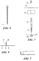
- a possible embodiment of the seam between the strips is shown in Fig. 4 in which the edge of one strip 2 is provided with a single angle bend 19, while the edge of the adjoining strip 2 has a backfolded bend 18 that folds over the simple bend 19.
- the height of the seam determines the stiffness of the sheet cladding, and thus, the stiffness of the entire panel element.
- the sheet cladding is fixed to the edge frame 1, advantageously, by means of spot-welding.
- the edge frame 1 of the panel element and the strips 2 of the sheet cladding are made from stainless sheet steel by bending.
- the strips 2 are manufactured with the help of a special tool from plain sheet steel, whereby onto the surface of the sheet cladding is embossed a desired pattern such as a diamond pattern, for instance, while the same tool simultaneously makes the bends along the edges of the strips.
- a desired pattern such as a diamond pattern
- the depth of the embossed pattern can be varied according to the requirements of the raw material and point of application, and if necessary, very deep embossments can be made.
- the strips must be made from a plain sheet, because in a ready-embossed sheet the pre-made pattern would cause bulging/buckling at the edge areas during their bending thus making the bends ill-defined.
- the material thickness of the edge frame 1 and the proportion of perforated holes relative to the total surface area of the edge frame are obviously selected according to the application, the material thickness is advantageously 0.2 - 0.4 mm and the proportion of the perforated holes approx. 50 % of the total area.
- the cladding sheet may be very thin, e.g., below 0.4 mm and sheet thicknesses even below 0.2 mm are advantageously used if minimum panel weight is desirable.
- the cladding material can be varied and the insulation of the element may be omitted.
- the cladding In the opposite case of manufacturing the panel element for use as a fire protection element, the cladding must be of sheet steel and the inside of the element must be filled with a suitable insulation material 9, 10 in order to prevent fire and heat from reaching structures located behind the element. Conventionally, different grades of mineral wool are used as insulation in these applications.
- the lightest possible fire protection element is achieved by filling the volume bordered by the edge frame 1 and the sheet cladding with soft and light mineral wool.
- the mineral wool is attached to the element with the help of sodium silicate and support wires 5.
- the number of the support wires 5 is two in the direction of the longer edge of the element and three in the direction of the shorter edge.
- the ends of the support wires 5 can be attached to the edge frame, and the crossing points of the wires 5 may be connected with the help of fixtures such as eyelets 4, twisted from a wire in the manner shown in Fig. 6, through which the wires are threaded.
- the insulation 9, 10 stays well fixed in the element tied with the help of sodium silicate and the support wires 5, and the wires may even be omitted if the element is used in a horizonal position in, e.g., a ceiling.
- the insulation is assembled from a number of layers 9, 10 covered by a foil. In such a multilayer structure, different kinds of mineral wools may be used in the superimposed layers.
- FIG. 3 the element is shown sectioned along the plane III - III. Additionally, this drawing shows an example of an insulation arrangement different from that illustrated in Fig. 2 in such a manner that ceramic wool 6, 7 of high temperature resistance is cut to shape and mounted behind the sheet cladding 2 tightly against the edge frame. The cavity enclosed by the ceramic wool 6, 7 is filled with soft mineral wool 8 of thermal insulation grade that may further be sealed inside a foil to prevent wetting of the wool. While this alternative insulation arrangement has the advantages of improved humidity and fire resistance as well as higher stiffness, it is heavier than the above-described element structure due to the use of the ceramic wool 6, 7.
- Fig. 3 also illustrates the structure of the tongue-and-groove edges of the frame 1.
- the tongue edge 1a forms a ridge with a cross section shaped as a truncated cone centered on the edge of the frame 1, and correspondingly, the groove edge 1b provides a compatible inward recessed cross section on the edge of the element frame.
- the edge of both the tongue and the groove section, 1a, 1b, respectively, remaining on the sheet cladding side of the frame section forms a lip 11 bent toward the center of the element.
- the sheet cladding is attached to the frame 1 so that a small gap remains between the surface of the cladding and the lip 11.
- the interelement seams can be concealed by means of a seal mould strip with lip edges which facilitate the fastening of the mould under said frame section lips.
- the interelement seam may also be caulked with a sealant to improve its water-tightness and fire resistance.
- Such a structure is particularly advantageous in fire protection elements, because thermal expansion at elevated temperature in a fire compresses the seams tighter together. As each element in such a situation acts elastically by virtue of the perforated edge frame, no distortion of the seams can occur even if a simple abutting seam is used as described above for the short edges of the element.
- the body of the fixture comprises two tubular elements: a body pipe 12 and a threaded, smaller-diameter pipe 13 attached to the end thereof.
- the outer surface of the threaded pipe 13 has a thread permitting the mounting of the pipe into a threaded hole made on a bulkhead, or alternatively, in a plain hole using a polyamide nut 20.
- the opposite end of the body pipe 12 has an internal thread for a screw 14, and additionally, the fixture comprises an insulating bushing 15 and a washer 17.
- the fixture is mounted on the bulkhead at a crossing point of element seams and the insulating bushing 15 is inserted on the body pipe 12.
- the elements are installed in place, whereby the body pipe 12 coincides with the interelement seam so that the pipe end remains slightly below the element surface, or maximally, extends flush with the element surface.
- the washer 17 can be placed over the crossing point of the seams and the screw 17 is tightened in place, whereby the washer 17 compresses the elements against the insulating bushing.
- Such a mounting fixture is advantageous owing to its small thermally conductive area due to the tubular body part.
- the present invention may have alternative embodiments.
- an element structure is shown suited for use in locations which require water-tightness as the covering is subject to splash water or must be washable.
- the interelement seam can be provided with a fold illustrated in Fig. 5 that guides water possibly entering the seam so as to flow at the lower edge of the seam to the outside of the covering.
- Water-tightness may also be improved by way of suitably varying the seam structure, and in fact, the shape of the edge frame of the element can be selected rather freely, since the element retains its elasticity properties even if the shape of the edge frame section is modified.
- the proportion of the perforated holes relative to the total area of the frame edge may be varied, while a relative hole area of 50 % is approximately optimal, and the relative hole area should be in the range 30 - 70 % to achieve desired elasticity, or alternatively, stiffness for the frame. Further, the proportional area of holes to be perforated is dependent on the thickness of the frame material and the shape of the frame section.
- the material of the sheet cladding may be varied according to point of application.
- the surface of the sheet cladding can be provided with different kinds of embossed patterns, which may be utilized to improve the stiffness of the sheet cladding. While the seams of the sheet structures of the panel element are advantageously made using spot-welding, obviously other joining methods can be used as well.
- the support wires of the thermal insulation are advantageously of stainless steel, but such steel wires may obviously be replaced by suitable wires made of, e.g., synthetic materials.
Applications Claiming Priority (2)
| Application Number | Priority Date | Filing Date | Title |
|---|---|---|---|
| FI950541 | 1995-02-08 | ||
| FI950541A FI109779B (fi) | 1995-02-08 | 1995-02-08 | Elementti pintaverhouksen valmistamiseksi ja elementti paloverhouksen valmistamiseksi |
Publications (2)
| Publication Number | Publication Date |
|---|---|
| EP0726199A1 EP0726199A1 (en) | 1996-08-14 |
| EP0726199B1 true EP0726199B1 (en) | 1999-09-01 |
Family
ID=8542804
Family Applications (1)
| Application Number | Title | Priority Date | Filing Date |
|---|---|---|---|
| EP19960850013 Expired - Lifetime EP0726199B1 (en) | 1995-02-08 | 1996-01-30 | Interior panel element |
Country Status (5)
| Country | Link |
|---|---|
| EP (1) | EP0726199B1 (fi) |
| DE (1) | DE69603992T2 (fi) |
| ES (1) | ES2138314T3 (fi) |
| FI (1) | FI109779B (fi) |
| NO (1) | NO308349B1 (fi) |
Families Citing this family (4)
| Publication number | Priority date | Publication date | Assignee | Title |
|---|---|---|---|---|
| CN100344841C (zh) * | 2003-06-06 | 2007-10-24 | 杨英达 | 一种金属面墙材墙板及其制作方法 |
| FR2872125B1 (fr) * | 2004-06-24 | 2006-10-27 | Alstom Sa | Cloison legere de type a |
| KR100809820B1 (ko) * | 2005-12-19 | 2008-03-04 | 비엔스틸라 주식회사 | 요철부를 구비한 금속 판부재를 이용한 선박용 패널 |
| CN110832148A (zh) * | 2018-05-11 | 2020-02-21 | 江苏源美竹木业有限责任公司 | 便于加工的复合防火板材及其制备方法 |
Family Cites Families (5)
| Publication number | Priority date | Publication date | Assignee | Title |
|---|---|---|---|---|
| GB114675A (en) * | 1917-04-18 | 1918-04-18 | John Davies | Improvements in and relating to the Method of and Means for Covering or Insulating Ships' Decks, Bulkheads, Walls, Floors, Ceilings and the like. |
| FR1006370A (fr) * | 1947-12-26 | 1952-04-22 | Revêtement métallique pour maçonneries | |
| SE7513704L (sv) * | 1975-12-04 | 1977-06-05 | Stora Kopparbergs Bergslags Ab | Golvelement |
| FR2618472B2 (fr) * | 1986-09-29 | 1989-12-01 | Rhenane Sa | Procede de bardage isolant |
| DE4333745A1 (de) * | 1993-10-04 | 1995-04-13 | Emmanuel Perrakis | Verkleidungselement für Schiffsinnenräume |
-
1995
- 1995-02-08 FI FI950541A patent/FI109779B/fi active
-
1996
- 1996-01-03 NO NO960021A patent/NO308349B1/no not_active IP Right Cessation
- 1996-01-30 ES ES96850013T patent/ES2138314T3/es not_active Expired - Lifetime
- 1996-01-30 DE DE1996603992 patent/DE69603992T2/de not_active Expired - Fee Related
- 1996-01-30 EP EP19960850013 patent/EP0726199B1/en not_active Expired - Lifetime
Also Published As
| Publication number | Publication date |
|---|---|
| FI109779B (fi) | 2002-10-15 |
| DE69603992T2 (de) | 2000-03-30 |
| DE69603992D1 (de) | 1999-10-07 |
| NO960021D0 (no) | 1996-01-03 |
| EP0726199A1 (en) | 1996-08-14 |
| NO960021L (no) | 1996-08-09 |
| FI950541A0 (fi) | 1995-02-08 |
| NO308349B1 (no) | 2000-09-04 |
| FI950541A (fi) | 1996-08-09 |
| ES2138314T3 (es) | 2000-01-01 |
Similar Documents
| Publication | Publication Date | Title |
|---|---|---|
| US5259157A (en) | Acoustical deck panel assembly | |
| US5299405A (en) | Wall assembly | |
| US5454449A (en) | Wall structure for an elevator, and an elevator car | |
| JPH08207883A (ja) | 支持構造に作り付けられた改良防水かつ断熱タンク | |
| IL129229A (en) | Composite structural member and wall assembly method | |
| KR0178981B1 (ko) | 빌딩, 주택, 선박의 내부 및 상부 구조에서 천장과 벽의 구조를 위한 스틸 카세트 | |
| KR100538079B1 (ko) | 벽구조 | |
| US5215806A (en) | Fire barrier material | |
| US6314698B1 (en) | Cladding panels of sheet metal or similar material for forming a coffered ceiling and a method for assembling of such panels | |
| EP0760042B1 (en) | Walls structure for cabins and the like | |
| EP0726199B1 (en) | Interior panel element | |
| JP2000118486A (ja) | 船用のプレハブ式キャビン及び該キャビンを船に設置する方法。 | |
| US5692347A (en) | Corrugated metal sheet | |
| GB2241466A (en) | Fire resistant materials | |
| AU2002255025B2 (en) | Sandwich building element | |
| EP0885337B1 (en) | Composite structural member | |
| JPH09184257A (ja) | 外囲体の音鳴防止構造 | |
| AU2002255025A1 (en) | Sandwich building element | |
| JP2930338B2 (ja) | 建築用パネル | |
| JPS5988558A (ja) | 建造物の面構造体 | |
| EP0775786A2 (en) | Building system for building a water, air and flame proof continuous facade | |
| JPH06294174A (ja) | 小屋裏界壁構造 | |
| KR100476153B1 (ko) | 선박의 내부 라이닝용 패널, 그 형성 방법 및 선박용 내화도어 | |
| KR860003227Y1 (ko) | 방화벽 | |
| ITMI992574A1 (it) | Struttura di pannello monolitico arcuato e termicamente ed acusticamente isolato particolarmente adatto per la copertura esterna di edifici |
Legal Events
| Date | Code | Title | Description |
|---|---|---|---|
| PUAI | Public reference made under article 153(3) epc to a published international application that has entered the european phase |
Free format text: ORIGINAL CODE: 0009012 |
|
| AK | Designated contracting states |
Kind code of ref document: A1 Designated state(s): BE DE ES GB IT NL SE |
|
| 17P | Request for examination filed |
Effective date: 19960919 |
|
| GRAG | Despatch of communication of intention to grant |
Free format text: ORIGINAL CODE: EPIDOS AGRA |
|
| 17Q | First examination report despatched |
Effective date: 19980918 |
|
| GRAG | Despatch of communication of intention to grant |
Free format text: ORIGINAL CODE: EPIDOS AGRA |
|
| GRAH | Despatch of communication of intention to grant a patent |
Free format text: ORIGINAL CODE: EPIDOS IGRA |
|
| GRAH | Despatch of communication of intention to grant a patent |
Free format text: ORIGINAL CODE: EPIDOS IGRA |
|
| RAP1 | Party data changed (applicant data changed or rights of an application transferred) |
Owner name: FY-INDUSTRIES OY |
|
| GRAA | (expected) grant |
Free format text: ORIGINAL CODE: 0009210 |
|
| AK | Designated contracting states |
Kind code of ref document: B1 Designated state(s): BE DE ES GB IT NL SE |
|
| REF | Corresponds to: |
Ref document number: 69603992 Country of ref document: DE Date of ref document: 19991007 |
|
| ITF | It: translation for a ep patent filed |
Owner name: SOCIETA' ITALIANA BREVETTI S.P.A. |
|
| REG | Reference to a national code |
Ref country code: ES Ref legal event code: FG2A Ref document number: 2138314 Country of ref document: ES Kind code of ref document: T3 |
|
| PLBE | No opposition filed within time limit |
Free format text: ORIGINAL CODE: 0009261 |
|
| STAA | Information on the status of an ep patent application or granted ep patent |
Free format text: STATUS: NO OPPOSITION FILED WITHIN TIME LIMIT |
|
| 26N | No opposition filed | ||
| NLS | Nl: assignments of ep-patents |
Owner name: FY-COMPOSITES OY |
|
| REG | Reference to a national code |
Ref country code: ES Ref legal event code: PC2A |
|
| REG | Reference to a national code |
Ref country code: GB Ref legal event code: 732E |
|
| REG | Reference to a national code |
Ref country code: GB Ref legal event code: IF02 |
|
| PGFP | Annual fee paid to national office [announced via postgrant information from national office to epo] |
Ref country code: NL Payment date: 20021227 Year of fee payment: 8 Ref country code: GB Payment date: 20021227 Year of fee payment: 8 |
|
| PGFP | Annual fee paid to national office [announced via postgrant information from national office to epo] |
Ref country code: SE Payment date: 20030109 Year of fee payment: 8 |
|
| PGFP | Annual fee paid to national office [announced via postgrant information from national office to epo] |
Ref country code: BE Payment date: 20030123 Year of fee payment: 8 |
|
| PGFP | Annual fee paid to national office [announced via postgrant information from national office to epo] |
Ref country code: ES Payment date: 20030124 Year of fee payment: 8 Ref country code: DE Payment date: 20030124 Year of fee payment: 8 |
|
| PG25 | Lapsed in a contracting state [announced via postgrant information from national office to epo] |
Ref country code: GB Free format text: LAPSE BECAUSE OF NON-PAYMENT OF DUE FEES Effective date: 20040130 |
|
| PG25 | Lapsed in a contracting state [announced via postgrant information from national office to epo] |
Ref country code: SE Free format text: LAPSE BECAUSE OF NON-PAYMENT OF DUE FEES Effective date: 20040131 Ref country code: ES Free format text: LAPSE BECAUSE OF NON-PAYMENT OF DUE FEES Effective date: 20040131 Ref country code: BE Free format text: LAPSE BECAUSE OF NON-PAYMENT OF DUE FEES Effective date: 20040131 |
|
| BERE | Be: lapsed |
Owner name: *FY-COMPOSITES OY Effective date: 20040131 |
|
| PG25 | Lapsed in a contracting state [announced via postgrant information from national office to epo] |
Ref country code: NL Free format text: LAPSE BECAUSE OF NON-PAYMENT OF DUE FEES Effective date: 20040801 |
|
| PG25 | Lapsed in a contracting state [announced via postgrant information from national office to epo] |
Ref country code: DE Free format text: LAPSE BECAUSE OF NON-PAYMENT OF DUE FEES Effective date: 20040803 |
|
| EUG | Se: european patent has lapsed | ||
| GBPC | Gb: european patent ceased through non-payment of renewal fee |
Effective date: 20040130 |
|
| NLV4 | Nl: lapsed or anulled due to non-payment of the annual fee |
Effective date: 20040801 |
|
| PG25 | Lapsed in a contracting state [announced via postgrant information from national office to epo] |
Ref country code: IT Free format text: LAPSE BECAUSE OF NON-PAYMENT OF DUE FEES Effective date: 20050130 |
|
| REG | Reference to a national code |
Ref country code: ES Ref legal event code: FD2A Effective date: 20040131 |