US5259157A - Acoustical deck panel assembly - Google Patents
Acoustical deck panel assembly Download PDFInfo
- Publication number
- US5259157A US5259157A US07/976,906 US97690692A US5259157A US 5259157 A US5259157 A US 5259157A US 97690692 A US97690692 A US 97690692A US 5259157 A US5259157 A US 5259157A
- Authority
- US
- United States
- Prior art keywords
- section
- insulation
- flat section
- flat
- improvement
- Prior art date
- Legal status (The legal status is an assumption and is not a legal conclusion. Google has not performed a legal analysis and makes no representation as to the accuracy of the status listed.)
- Expired - Fee Related
Links
- 238000009413 insulation Methods 0.000 claims abstract description 57
- 125000006850 spacer group Chemical group 0.000 claims abstract description 15
- 239000011152 fibreglass Substances 0.000 claims description 7
- 239000003973 paint Substances 0.000 claims description 4
- 238000010422 painting Methods 0.000 claims description 2
- 238000000034 method Methods 0.000 claims 4
- 239000002184 metal Substances 0.000 description 18
- 239000002131 composite material Substances 0.000 description 5
- 230000000712 assembly Effects 0.000 description 3
- 238000000429 assembly Methods 0.000 description 3
- 229910000831 Steel Inorganic materials 0.000 description 2
- 239000010440 gypsum Substances 0.000 description 2
- 229910052602 gypsum Inorganic materials 0.000 description 2
- 239000010959 steel Substances 0.000 description 2
- 239000010426 asphalt Substances 0.000 description 1
- 238000010276 construction Methods 0.000 description 1
- 238000007796 conventional method Methods 0.000 description 1
- 239000003365 glass fiber Substances 0.000 description 1
- 238000009434 installation Methods 0.000 description 1
- 239000000463 material Substances 0.000 description 1
- 230000036963 noncompetitive effect Effects 0.000 description 1
- 239000004033 plastic Substances 0.000 description 1
Images


Classifications
-
- E—FIXED CONSTRUCTIONS
- E04—BUILDING
- E04F—FINISHING WORK ON BUILDINGS, e.g. STAIRS, FLOORS
- E04F13/00—Coverings or linings, e.g. for walls or ceilings
- E04F13/07—Coverings or linings, e.g. for walls or ceilings composed of covering or lining elements; Sub-structures therefor; Fastening means therefor
- E04F13/08—Coverings or linings, e.g. for walls or ceilings composed of covering or lining elements; Sub-structures therefor; Fastening means therefor composed of a plurality of similar covering or lining elements
- E04F13/0867—Coverings or linings, e.g. for walls or ceilings composed of covering or lining elements; Sub-structures therefor; Fastening means therefor composed of a plurality of similar covering or lining elements having acoustic absorption means on the visible surface
-
- E—FIXED CONSTRUCTIONS
- E01—CONSTRUCTION OF ROADS, RAILWAYS, OR BRIDGES
- E01F—ADDITIONAL WORK, SUCH AS EQUIPPING ROADS OR THE CONSTRUCTION OF PLATFORMS, HELICOPTER LANDING STAGES, SIGNS, SNOW FENCES, OR THE LIKE
- E01F8/00—Arrangements for absorbing or reflecting air-transmitted noise from road or railway traffic
- E01F8/0005—Arrangements for absorbing or reflecting air-transmitted noise from road or railway traffic used in a wall type arrangement
- E01F8/0047—Arrangements for absorbing or reflecting air-transmitted noise from road or railway traffic used in a wall type arrangement with open cavities, e.g. for covering sunken roads
- E01F8/0064—Perforated plate or mesh, e.g. as wall facing
- E01F8/007—Perforated plate or mesh, e.g. as wall facing with damping material
-
- E—FIXED CONSTRUCTIONS
- E04—BUILDING
- E04B—GENERAL BUILDING CONSTRUCTIONS; WALLS, e.g. PARTITIONS; ROOFS; FLOORS; CEILINGS; INSULATION OR OTHER PROTECTION OF BUILDINGS
- E04B5/00—Floors; Floor construction with regard to insulation; Connections specially adapted therefor
- E04B5/02—Load-carrying floor structures formed substantially of prefabricated units
-
- E—FIXED CONSTRUCTIONS
- E04—BUILDING
- E04D—ROOF COVERINGS; SKY-LIGHTS; GUTTERS; ROOF-WORKING TOOLS
- E04D13/00—Special arrangements or devices in connection with roof coverings; Protection against birds; Roof drainage ; Sky-lights
- E04D13/16—Insulating devices or arrangements in so far as the roof covering is concerned, e.g. characterised by the material or composition of the roof insulating material or its integration in the roof structure
- E04D13/1606—Insulation of the roof covering characterised by its integration in the roof structure
- E04D13/1643—Insulation of the roof covering characterised by its integration in the roof structure the roof structure being formed by load bearing corrugated sheets, e.g. profiled sheet metal roofs
Definitions
- This invention relates to metal roof and floor deck assemblies and more particularly to acoustical roof and floor panel assemblies having structural integrity, efficient sound absorbing properties and superior thermal insulation values.
- acoustical roof decking consists of a metal panel which forms a balanced section over the ceiling supports.
- balanced section it is meant that the panels include alternating flat sections and ribs of approximately the same width.
- perforations are placed in the sidewalls of the ribs and not on the flat surfaces which form the ceiling and which extend between ribs. Fiberglass units are then laid in the ribs to complete the acoustical ceiling.
- Fenestra Incorporated produced an acoustical roof in which the width of the flat sections substantially exceeded the width of the ribs and perforations occurred along the flat sections.
- This product included a sound absorbing element formed of a formed arched pad, 1 inch thick, molded from a 1 pound density, extra fine glass fiber. The sound absorbing element was placed between the ribs and a ply of roofing felt was laid dry over the tops of the exposed ribs and sound absorbing element to form a vapor seal and asphalt stop.
- the insulation element had an arched configuration, special equipment had to be designed and the insulation custom made. This substantially increased the cost of the product so as to be noncompetitive with the conventional prior art acoustical deck.
- My acoustical roof panel assembly accomplishes all of the above-stated objectives and consists of a plurality of roof deck panels assembled in side-by-side and/or end-to-end relationship and secured to roof supports such as purlins with each panel including a plurality of parallel and spaced apart perforated flat sections, with each flat section being separated from its adjacent flat section by a frusto-pyramidal rib section.
- the flat sections as measured in the plane of the flat sections, have a width at least three times greater than the width of the rib and preferably a width five times greater than the width of the rib. Lengths of insulation are positioned between the ribs and atop a spacer means which spaces the insulation from the inner surface of the flat sections.
- the preferred spacer is a reticulated wire mesh positioned in contact with and between each of the perforated flat sections and the length of insulation positioned between adjacent ribs.
- the insulation is preferably fiberglass and the assembly has a noise reduction coefficient on the order of 0.95 to 1. There preferably are no perforations in the area of the ribs.
- the panels may include insulation cover plates which allow the roof panels to be utilized for a composite floor deck. Concrete may be added on top of the panels to complete the composite floor deck. Each cover plate protects the acoustical insulation from the concrete and prevents the concrete from going through the perforations in the flat sections.
- FIG. 1 is a perspective view partly in section of a portion of an entire roof assembly including a pair of acoustical ceiling roof panel units;
- FIG. 2 is a perspective view partly in section showing a portion of the acoustical ceiling roof panel unit
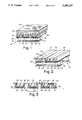
- FIG. 3 is a section of a portion of the acoustical ceiling roof panel unit
- FIG. 4 is a perspective view of a portion of a metal panel
- FIG. 5 is a top view of the metal panel
- FIG. 6 is a perspective view of the reticulated metal mesh spacer
- FIG. 7 is a perspective view of the fiberglass insulation
- FIG. 8 is a section of a portion of modified roof and floor assembly.
- FIG. 1 A portion of an entire roof system, including the acoustical ceiling roof panel assembly, generally designated 10 is illustrated in FIG. 1.
- the roof panel assembly 10 which includes a metal roof deck panel 12, is positioned on transversely extending purlins 14 which are generally spaced on 6 foot to 12 foot centers and are connected to the building superstructure by conventional means recognized in the art.
- the acoustical ceiling roof panel assembly 10 is connected to the purlins 14 by welds 32 with the size and location of the welds being in compliance with conventional or specified erection instructions.
- the assembly 10 is then covered with a thin gypsum board 34, which in turn is covered with conventional thermal insulation 36.
- the thermal insulation 36 is secured in place by means of threaded fasteners and fastener plates 37 which connect to the gypsum board 34 or metal roof deck panels 12.
- the thermal insulation 36 is normally covered with a single ply plastic material (not shown), although it will be recognized that other forms of conventional roof construction can be used in conjunction with the acoustical ceiling roof panel assembly 10 of my invention.
- the entire assembly 10 is best seen in FIGS. 2 and 3.
- the individual components of the assembly 10 are metal panel 12, wire mesh 20 and acoustic insulation 22.
- the structural component of the assembly 10 is the metal roof deck panel 12 shown in FIGS. 4 and 5.
- This panel 12 is roll-formed from coils of the appropriate gauge coated steel or uncoated steel (example: 16 to 22 gauge), which are then cut into specified sheet lengths.
- Each panel 12 consists of parallel extending alternately positioned flat sections 16 and ribs 18.
- the panels 12 terminate along their longitudinal edges in side laps 19 normally of the interlocking type so that panels can be joined in side-by-side relationship, see FIG. 3.
- the panels may also terminate in end laps so that panels may likewise be positioned in end-to-end relationships.
- the side laps and end laps are conventional and do not form a part of this invention.
- the flat sections 16 contain a substantial plurality of perforations 24.
- the number of perforations will vary depending upon the acoustical requirements. A typical requirement would be 1/8 inch round holes of approximately 1100 per square foot.
- the ribs 18 are formed by two diverging side walls 28 each of which connects to an adjacent flat section 16.
- a top wall 30 connects the diverging end walls 28 to each other.
- the top wall 30 extends in a plane parallel to the plane of the flat sections 16.
- the ribs 18 are frusto-pyramidal in cross section.
- the flat sections 16 have a width dimension as measured in the plane P of the flat sections, shown as Y in FIG. 3, generally at least three times and preferably five times greater than the width dimension of ribs 18, shown as X.
- the typical width for a flat section 16 would be 51/2 inches as measured in the plane P of the flat sections 16.
- the rib 18 would generally have a width X of between 11/2 inches to 15/8 inches and an opening in the plane P of the flat sections 16 of 5/8 inch.
- the depth of the rib 18 would typically be 2 inches.
- a typical panel may be 2 feet wide and consists of four flat sections and three ribs, another typical panel contains two ribs and three flat sections.
- the reticulated expanded metal mesh 20 is positioned between the ribs 18 adjacent to a top surface 40 of flat 16, see FIGS. 3 and 6.
- the metal mesh acts as a spacer between the panel and the fiberglass insulation 22.
- the metal mesh 20 which is a conventional expanded metal wire permits painting of the exposed bottom surface of the flat sections 16 without getting a lot of paint on the insulation 22. Paint detrimentally affects the acoustical properties of the insulation 22.
- the insulation 22 on the wire mesh 20 some advantage is achieved in the sound deadening capacity of the assembly 10.
- the bottom surface 42 of the panel 12 is painted with a finish coat after it is attached to the purlins 14, and the mesh 20 and insulation 22 are set in place.
- the insulation 22, best seen in FIG. 7, is preferably a fiberglass type of insulation having a density on the order of 3 pounds per cubic foot and a thickness of 2 inches.
- the panel assembly 10 of the type described hereinabove will have a noise reduction coefficient on the order of 0.95 to 1. Further, it is easily assembled and does not require any custom fabricated components. Finally, the structural integrity of the metal panel is maintained even though the flat sections of the metal panel are substantially perforated.
- panel 12 which does not have a painted finish coat, is first attached to the purlin 14. Then the mesh 20 is set in place and the insulation 22 is then placed on top of the mesh 20 so that the mesh 20 is positioned between the flat sections 16 and the insulation 22. The panel 12 and purlin 14 are then painted with the finish coat.
- FIG. 8 discloses an alternative roof and floor panel assembly 50 which allows the assembly 50 to be used for a composite roof or floor deck.
- the assembly 50 includes metal roof deck panel 12 containing ribs 18 and flat sections 16 with perforations 24, wire mesh 20 and insulation 22 as described above. However, when the present system is used as a composite floor or roof deck, the wire mesh 20 and 11/2 inch thick insulation 22 are installed prior to insulation cover plates 52, with the spans of the panels 12 being up to 15 feet.
- the assembly 50 includes the insulation cover plates 52 extending between adjacent ribs 18 and cooperating with the flat sections 16 to substantially cover the insulation 22, wire mesh 20 and perforations 24. Concrete 54 is placed on the composite roof or floor deck.
- the insulation cover plates 52 protect the insulation 22 from the concrete and prevents the concrete from going through the perforations 24.
- the insulation cover plates 52 allow the concrete 54 to substantially surround the ribs 18 to provide sufficient interlocking between the concrete 54 and panels 12.
- the modified roof and floor assembly 50 has a noise reduction coefficient on the order of 0.75 and is particularly well-suited for multilevel structures.
- the typical dimensions for the roof and floor assembly 50 as shown in FIG. 8 include:
- width Y of each of the flat sections 16 in plane of flat sections is about 51/2 inches;
- each of the ribs 18 is about 15/8 inches;
- gap Z between adjacent flat sections 16 in plane of flat sections 16 is about 5/8 inch;
- depth D of the ribs 18 is about 2 inches
- depth B of the insulation cover plates 52 is about 11/2 inches
- centerline distance C between adjacent ribs 18 is about 61/8 inches
- width L of effective insulation is about 4 inches
- width M of the top of insulation cover plates 52 is about 3 inches
- gap G between sides 28 and insulation cover plates 52 is about 11/16 inch
- spacing S between adjacent ribs 18 is about 41/2 inches.
Landscapes
- Engineering & Computer Science (AREA)
- Architecture (AREA)
- Civil Engineering (AREA)
- Structural Engineering (AREA)
- Physics & Mathematics (AREA)
- Acoustics & Sound (AREA)
- Electromagnetism (AREA)
- Building Environments (AREA)
Abstract
Description
Claims (18)
Priority Applications (1)
| Application Number | Priority Date | Filing Date | Title |
|---|---|---|---|
| US07/976,906 US5259157A (en) | 1991-05-31 | 1992-11-16 | Acoustical deck panel assembly |
Applications Claiming Priority (2)
| Application Number | Priority Date | Filing Date | Title |
|---|---|---|---|
| US07/707,874 US5172527A (en) | 1991-05-31 | 1991-05-31 | Acoustical deck panel assembly |
| US07/976,906 US5259157A (en) | 1991-05-31 | 1992-11-16 | Acoustical deck panel assembly |
Related Parent Applications (1)
| Application Number | Title | Priority Date | Filing Date |
|---|---|---|---|
| US07/707,874 Continuation-In-Part US5172527A (en) | 1991-05-31 | 1991-05-31 | Acoustical deck panel assembly |
Publications (1)
| Publication Number | Publication Date |
|---|---|
| US5259157A true US5259157A (en) | 1993-11-09 |
Family
ID=27107981
Family Applications (1)
| Application Number | Title | Priority Date | Filing Date |
|---|---|---|---|
| US07/976,906 Expired - Fee Related US5259157A (en) | 1991-05-31 | 1992-11-16 | Acoustical deck panel assembly |
Country Status (1)
| Country | Link |
|---|---|
| US (1) | US5259157A (en) |
Cited By (45)
| Publication number | Priority date | Publication date | Assignee | Title |
|---|---|---|---|---|
| US5560150A (en) * | 1995-02-15 | 1996-10-01 | Professional Systems, Inc. | Structure for telecommunications equipment enclosure |
| US6151854A (en) * | 1997-07-24 | 2000-11-28 | Gutjahr; Walter | Profiled web for venting and draining floor tiles, particularly ceramic tiles, laid in a thin retaining layer |
| US6357191B1 (en) | 2000-02-03 | 2002-03-19 | Epic Metals Corporation | Composite deck |
| US20040000107A1 (en) * | 2002-07-01 | 2004-01-01 | Landis David F. | Decking for receipt of skylights |
| US6691482B1 (en) | 2001-02-16 | 2004-02-17 | Epic Metals Corporation | Decking |
| US20040050001A1 (en) * | 2002-09-11 | 2004-03-18 | Williams Jonathan P. | Building foundation with unique slab and wall assembly, external sump, and void retention dam |
| US20050257471A1 (en) * | 2001-08-30 | 2005-11-24 | Stevens Donald A | Structural panel utilizing a lath and frame member and method for making the same |
| US20060053717A1 (en) * | 2004-08-23 | 2006-03-16 | Kelly Thomas L | Fire retardant roof structure for styrene insulated roofs and method for making the same |
| WO2006097065A1 (en) * | 2005-03-15 | 2006-09-21 | Werner Averkamp | Floor supporting structure with filled or covered cavities |
| US20060230699A1 (en) * | 2005-03-22 | 2006-10-19 | Keene James R | Sound control flooring systems and methods therefor |
| US7131239B2 (en) * | 2002-04-09 | 2006-11-07 | Williams Jonathan P | Structural slab and wall assembly for use with expansive soils |
| US20060257210A1 (en) * | 2005-05-11 | 2006-11-16 | Williams Jonathan P | Residential basement flooring system and method using pier capitals for supporting pre-cast slabs |
| US7146920B1 (en) | 2005-03-21 | 2006-12-12 | Epic Metals Corporation | Three dimensional plated deck |
| US20070245668A1 (en) * | 2004-03-05 | 2007-10-25 | Gabriele Raineri | Panel with Pre-Placed Tiles for Laying Floors |
| US20070271866A1 (en) * | 2004-01-27 | 2007-11-29 | Stevens Donald A | Framing System and Method for Assembling the Same |
| US20090293280A1 (en) * | 2008-05-27 | 2009-12-03 | Gharibeh Rene A | Method of making a composite building panel |
| USD608464S1 (en) | 2009-02-27 | 2010-01-19 | Epic Metals Corporation | Decking |
| USD623773S1 (en) | 2009-01-14 | 2010-09-14 | Epic Metals Corporation | Decking element |
| US20110030307A1 (en) * | 2009-08-10 | 2011-02-10 | Caterpillar Inc. | Concrete bar slag container |
| US8146310B2 (en) | 2009-03-11 | 2012-04-03 | Keene Building Products Co., Inc. | Noise control flooring system |
| USD661410S1 (en) | 2011-01-21 | 2012-06-05 | Epic Metals Corporation | Acoustical roof deck |
| USD663045S1 (en) | 2011-09-28 | 2012-07-03 | Epic Metals Corporation | Decking |
| US8240095B1 (en) * | 2010-01-20 | 2012-08-14 | Consolidated Systems, Inc. | Deck assembly with liner panel |
| USD677405S1 (en) | 2010-06-09 | 2013-03-05 | Epic Metals Corporation | Sun screen panel |
| US8505259B1 (en) | 2009-09-17 | 2013-08-13 | Consolidated Systems, Inc. | Built-up deep deck unit for a roof or floor |
| US8528286B2 (en) | 2009-11-10 | 2013-09-10 | Keene Building Products Co., Inc. | Sound control mat |
| US8572900B1 (en) | 2010-01-22 | 2013-11-05 | Epic Metals Corporation | Decking having a removable rib |
| US20140060775A1 (en) * | 2011-05-04 | 2014-03-06 | H.D.S Technology Ag | Room enclosure assembly, method for producing same and element therefor |
| US20140115980A1 (en) * | 2012-11-01 | 2014-05-01 | 3M Innovative Properties Company | Above-deck roof venting article |
| USD713554S1 (en) | 2013-01-15 | 2014-09-16 | Epic Metals Corporation | Roof decking |
| US8881469B1 (en) | 2010-11-18 | 2014-11-11 | Consolidated Systems, Inc. | Cellular ceiling deck system with hidden hinges |
| CN104295009A (en) * | 2014-10-15 | 2015-01-21 | 苏州工业园区设计研究院股份有限公司 | Deformation joint structure of planted roof |
| USD721826S1 (en) | 2013-01-15 | 2015-01-27 | Epic Metals Corporation | Roof decking |
| US20150211237A1 (en) * | 2014-01-27 | 2015-07-30 | Tai Ye Enterprises Ltd. | Wall unit used in construction |
| USD742541S1 (en) | 2013-12-13 | 2015-11-03 | Epic Metals Corporation | Roofing deck ceiling system |
| US20150345514A1 (en) * | 2014-06-02 | 2015-12-03 | Carrier Corporation | Acoustic treatment for an indoor hvac component |
| ES2573202A1 (en) * | 2014-12-04 | 2016-06-06 | Universidad De Valladolid | Acoustic panel and acoustic barrier (Machine-translation by Google Translate, not legally binding) |
| US20170292278A1 (en) * | 2014-04-24 | 2017-10-12 | Ardex Anlagen Gmbh | Decoupling mat for a surface covering structure that can be covered by covering elements |
| US20190112807A1 (en) * | 2017-10-17 | 2019-04-18 | Alexandre C. DUCHARME | Vibration absorption device and method for acoustic insulation |
| USD1013902S1 (en) * | 2021-05-18 | 2024-02-06 | James Hardie Technology Limited | Base trim strip |
| USD1016339S1 (en) * | 2022-06-03 | 2024-02-27 | Tate Access Floors, Inc. | Decking and strut member for data center ceiling |
| USD1018907S1 (en) * | 2021-11-15 | 2024-03-19 | Cheng Uei Precision Industry Co., Ltd. | Metal sheet |
| EE01641U1 (en) * | 2021-11-11 | 2024-08-15 | Rautaruukki Oyj | Acustic profile |
| USD1105497S1 (en) | 2022-04-28 | 2025-12-09 | Verco Decking, Inc. | Dovetail decking panel |
| US12529221B2 (en) | 2022-04-28 | 2026-01-20 | Verco Decking, Inc. | Dovetail decking system with a full top flange sidelap and method of securing |
Citations (18)
| Publication number | Priority date | Publication date | Assignee | Title |
|---|---|---|---|---|
| US840016A (en) * | 1905-12-26 | 1907-01-01 | Berger Mfg Co | Binding-sheet for concrete-work. |
| US1317519A (en) * | 1919-09-30 | Planoqraph co | ||
| US1899403A (en) * | 1932-04-08 | 1933-02-28 | Frederick M Venzie | Building construction |
| US2001733A (en) * | 1932-01-02 | 1935-05-21 | Johns Manville | Sound deadening structure |
| US2007374A (en) * | 1932-07-25 | 1935-07-09 | United States Gypsum Co | Acoustical roof deck |
| US2047109A (en) * | 1935-12-16 | 1936-07-07 | George E Nagel | Precast insulated concrete deck slab |
| US2052984A (en) * | 1934-04-25 | 1936-09-01 | Jennie M Madison | Trussed-sheet construction |
| US2090483A (en) * | 1936-01-02 | 1937-08-17 | American Car & Foundry Co | Key arch flooring |
| US2112631A (en) * | 1936-01-06 | 1938-03-29 | Kenneth Taylor H | Sound absorbing construction |
| US2130285A (en) * | 1937-07-19 | 1938-09-13 | C Marqua Edward | Ceiling structure |
| US2148496A (en) * | 1936-12-31 | 1939-02-28 | Owens Corning Fiberglass Corp | Installation of acoustical insulating material |
| US2219806A (en) * | 1938-08-04 | 1940-10-29 | Buttress Board Company | Hollow rib lath |
| US2271929A (en) * | 1942-02-03 | Building interior construction | ||
| US2293351A (en) * | 1939-12-16 | 1942-08-18 | Celotex Corp | Sound absorbing construction |
| US3147926A (en) * | 1962-03-12 | 1964-09-08 | Maurice C Rosenblatt | Acoustical and luminous ceiling structure |
| US4330046A (en) * | 1979-09-28 | 1982-05-18 | Armand Lerner | Sound barrier |
| US4685259A (en) * | 1986-02-14 | 1987-08-11 | Peabody Noise Control, Inc. | Sound rated floor system and method of constructing same |
| US5172527A (en) * | 1991-05-31 | 1992-12-22 | Epic Metals Corporation | Acoustical deck panel assembly |
-
1992
- 1992-11-16 US US07/976,906 patent/US5259157A/en not_active Expired - Fee Related
Patent Citations (18)
| Publication number | Priority date | Publication date | Assignee | Title |
|---|---|---|---|---|
| US2271929A (en) * | 1942-02-03 | Building interior construction | ||
| US1317519A (en) * | 1919-09-30 | Planoqraph co | ||
| US840016A (en) * | 1905-12-26 | 1907-01-01 | Berger Mfg Co | Binding-sheet for concrete-work. |
| US2001733A (en) * | 1932-01-02 | 1935-05-21 | Johns Manville | Sound deadening structure |
| US1899403A (en) * | 1932-04-08 | 1933-02-28 | Frederick M Venzie | Building construction |
| US2007374A (en) * | 1932-07-25 | 1935-07-09 | United States Gypsum Co | Acoustical roof deck |
| US2052984A (en) * | 1934-04-25 | 1936-09-01 | Jennie M Madison | Trussed-sheet construction |
| US2047109A (en) * | 1935-12-16 | 1936-07-07 | George E Nagel | Precast insulated concrete deck slab |
| US2090483A (en) * | 1936-01-02 | 1937-08-17 | American Car & Foundry Co | Key arch flooring |
| US2112631A (en) * | 1936-01-06 | 1938-03-29 | Kenneth Taylor H | Sound absorbing construction |
| US2148496A (en) * | 1936-12-31 | 1939-02-28 | Owens Corning Fiberglass Corp | Installation of acoustical insulating material |
| US2130285A (en) * | 1937-07-19 | 1938-09-13 | C Marqua Edward | Ceiling structure |
| US2219806A (en) * | 1938-08-04 | 1940-10-29 | Buttress Board Company | Hollow rib lath |
| US2293351A (en) * | 1939-12-16 | 1942-08-18 | Celotex Corp | Sound absorbing construction |
| US3147926A (en) * | 1962-03-12 | 1964-09-08 | Maurice C Rosenblatt | Acoustical and luminous ceiling structure |
| US4330046A (en) * | 1979-09-28 | 1982-05-18 | Armand Lerner | Sound barrier |
| US4685259A (en) * | 1986-02-14 | 1987-08-11 | Peabody Noise Control, Inc. | Sound rated floor system and method of constructing same |
| US5172527A (en) * | 1991-05-31 | 1992-12-22 | Epic Metals Corporation | Acoustical deck panel assembly |
Non-Patent Citations (1)
| Title |
|---|
| Holorib acoustic roofs, Fenestra Incorporated, p. 25. * |
Cited By (65)
| Publication number | Priority date | Publication date | Assignee | Title |
|---|---|---|---|---|
| US5560150A (en) * | 1995-02-15 | 1996-10-01 | Professional Systems, Inc. | Structure for telecommunications equipment enclosure |
| US6151854A (en) * | 1997-07-24 | 2000-11-28 | Gutjahr; Walter | Profiled web for venting and draining floor tiles, particularly ceramic tiles, laid in a thin retaining layer |
| US6357191B1 (en) | 2000-02-03 | 2002-03-19 | Epic Metals Corporation | Composite deck |
| US6691482B1 (en) | 2001-02-16 | 2004-02-17 | Epic Metals Corporation | Decking |
| US20050257471A1 (en) * | 2001-08-30 | 2005-11-24 | Stevens Donald A | Structural panel utilizing a lath and frame member and method for making the same |
| US7921617B2 (en) | 2001-08-30 | 2011-04-12 | Stevens Donald A | Structural panel utilizing a lath and frame member and method for making the same |
| US20090229207A1 (en) * | 2001-08-30 | 2009-09-17 | Stevens Donald A | Structural Panel Utilizing A Lath And Fram Member And Method For Making The Same |
| US7131239B2 (en) * | 2002-04-09 | 2006-11-07 | Williams Jonathan P | Structural slab and wall assembly for use with expansive soils |
| US20040000107A1 (en) * | 2002-07-01 | 2004-01-01 | Landis David F. | Decking for receipt of skylights |
| US20040050001A1 (en) * | 2002-09-11 | 2004-03-18 | Williams Jonathan P. | Building foundation with unique slab and wall assembly, external sump, and void retention dam |
| US7003918B2 (en) | 2002-09-11 | 2006-02-28 | Williams Jonathan P | Building foundation with unique slab and wall assembly, external sump, and void retention dam |
| US20070271866A1 (en) * | 2004-01-27 | 2007-11-29 | Stevens Donald A | Framing System and Method for Assembling the Same |
| US20070245668A1 (en) * | 2004-03-05 | 2007-10-25 | Gabriele Raineri | Panel with Pre-Placed Tiles for Laying Floors |
| US7877955B2 (en) | 2004-08-23 | 2011-02-01 | Kelly Thomas L | Fire retardant roof structure for styrene insulated roofs and method for making the same |
| US20060053717A1 (en) * | 2004-08-23 | 2006-03-16 | Kelly Thomas L | Fire retardant roof structure for styrene insulated roofs and method for making the same |
| US20080216429A1 (en) * | 2004-08-23 | 2008-09-11 | Kelly Thomas L | Fire retardant roof structure for styrene insulated roofs and method for making the same |
| US7454876B2 (en) * | 2004-08-23 | 2008-11-25 | Kelly Thomas L | Fire retardant roof structure for styrene insulated roofs and method for making the same |
| WO2006097065A1 (en) * | 2005-03-15 | 2006-09-21 | Werner Averkamp | Floor supporting structure with filled or covered cavities |
| US7328667B1 (en) | 2005-03-21 | 2008-02-12 | Epic Metals Corporation | Three dimensional plated deck |
| US7146920B1 (en) | 2005-03-21 | 2006-12-12 | Epic Metals Corporation | Three dimensional plated deck |
| US20060230699A1 (en) * | 2005-03-22 | 2006-10-19 | Keene James R | Sound control flooring systems and methods therefor |
| US20060257210A1 (en) * | 2005-05-11 | 2006-11-16 | Williams Jonathan P | Residential basement flooring system and method using pier capitals for supporting pre-cast slabs |
| US20090293419A1 (en) * | 2008-05-27 | 2009-12-03 | Gharibeh Rene A | Composite Building Panel |
| US7739844B2 (en) * | 2008-05-27 | 2010-06-22 | American Fortress Homes, Inc. | Composite building panel |
| US7836660B2 (en) * | 2008-05-27 | 2010-11-23 | American Fortress Homes, Inc. | Method of making a composite building panel |
| US20090293280A1 (en) * | 2008-05-27 | 2009-12-03 | Gharibeh Rene A | Method of making a composite building panel |
| USD623773S1 (en) | 2009-01-14 | 2010-09-14 | Epic Metals Corporation | Decking element |
| USD655022S1 (en) | 2009-01-14 | 2012-02-28 | Epic Metals Corporation | Decking |
| USD648445S1 (en) | 2009-01-14 | 2011-11-08 | Epic Metals Corporation | Decking element |
| USD622417S1 (en) | 2009-02-27 | 2010-08-24 | Epic Metals Corporation | Decking |
| USD608464S1 (en) | 2009-02-27 | 2010-01-19 | Epic Metals Corporation | Decking |
| US8146310B2 (en) | 2009-03-11 | 2012-04-03 | Keene Building Products Co., Inc. | Noise control flooring system |
| US20110030307A1 (en) * | 2009-08-10 | 2011-02-10 | Caterpillar Inc. | Concrete bar slag container |
| US8505259B1 (en) | 2009-09-17 | 2013-08-13 | Consolidated Systems, Inc. | Built-up deep deck unit for a roof or floor |
| US8528286B2 (en) | 2009-11-10 | 2013-09-10 | Keene Building Products Co., Inc. | Sound control mat |
| US8240095B1 (en) * | 2010-01-20 | 2012-08-14 | Consolidated Systems, Inc. | Deck assembly with liner panel |
| US8572900B1 (en) | 2010-01-22 | 2013-11-05 | Epic Metals Corporation | Decking having a removable rib |
| USD677405S1 (en) | 2010-06-09 | 2013-03-05 | Epic Metals Corporation | Sun screen panel |
| US8881469B1 (en) | 2010-11-18 | 2014-11-11 | Consolidated Systems, Inc. | Cellular ceiling deck system with hidden hinges |
| USD661410S1 (en) | 2011-01-21 | 2012-06-05 | Epic Metals Corporation | Acoustical roof deck |
| US20140060775A1 (en) * | 2011-05-04 | 2014-03-06 | H.D.S Technology Ag | Room enclosure assembly, method for producing same and element therefor |
| US9273870B2 (en) * | 2011-05-04 | 2016-03-01 | H.D.S. Technology Ag | Room enclosure assembly, method for producing same and element therefor |
| USD663045S1 (en) | 2011-09-28 | 2012-07-03 | Epic Metals Corporation | Decking |
| US20140115980A1 (en) * | 2012-11-01 | 2014-05-01 | 3M Innovative Properties Company | Above-deck roof venting article |
| US9228355B2 (en) * | 2012-11-01 | 2016-01-05 | 3M Innovative Properties Company | Above-deck roof venting article |
| USD713554S1 (en) | 2013-01-15 | 2014-09-16 | Epic Metals Corporation | Roof decking |
| USD721826S1 (en) | 2013-01-15 | 2015-01-27 | Epic Metals Corporation | Roof decking |
| USD742541S1 (en) | 2013-12-13 | 2015-11-03 | Epic Metals Corporation | Roofing deck ceiling system |
| USD817519S1 (en) | 2013-12-13 | 2018-05-08 | Epic Metals Corporation | Roofing deck ceiling system |
| USD785209S1 (en) | 2013-12-13 | 2017-04-25 | Epic Metals Corporation | Roofing deck ceiling system |
| US20150211237A1 (en) * | 2014-01-27 | 2015-07-30 | Tai Ye Enterprises Ltd. | Wall unit used in construction |
| US10968641B2 (en) * | 2014-04-24 | 2021-04-06 | Ardex Anlagen Gmbh | Decoupling mat for a surface covering structure that can be covered by covering elements |
| US20170292278A1 (en) * | 2014-04-24 | 2017-10-12 | Ardex Anlagen Gmbh | Decoupling mat for a surface covering structure that can be covered by covering elements |
| US20150345514A1 (en) * | 2014-06-02 | 2015-12-03 | Carrier Corporation | Acoustic treatment for an indoor hvac component |
| US10774845B2 (en) * | 2014-06-02 | 2020-09-15 | Carrier Corporation | Acoustic treatment for an indoor HVAC component |
| CN104295009A (en) * | 2014-10-15 | 2015-01-21 | 苏州工业园区设计研究院股份有限公司 | Deformation joint structure of planted roof |
| ES2573202A1 (en) * | 2014-12-04 | 2016-06-06 | Universidad De Valladolid | Acoustic panel and acoustic barrier (Machine-translation by Google Translate, not legally binding) |
| US20190112807A1 (en) * | 2017-10-17 | 2019-04-18 | Alexandre C. DUCHARME | Vibration absorption device and method for acoustic insulation |
| US11661739B2 (en) * | 2017-10-17 | 2023-05-30 | Développement R & D | Vibration absorption device and method for acoustic insulation |
| USD1013902S1 (en) * | 2021-05-18 | 2024-02-06 | James Hardie Technology Limited | Base trim strip |
| EE01641U1 (en) * | 2021-11-11 | 2024-08-15 | Rautaruukki Oyj | Acustic profile |
| USD1018907S1 (en) * | 2021-11-15 | 2024-03-19 | Cheng Uei Precision Industry Co., Ltd. | Metal sheet |
| USD1105497S1 (en) | 2022-04-28 | 2025-12-09 | Verco Decking, Inc. | Dovetail decking panel |
| US12529221B2 (en) | 2022-04-28 | 2026-01-20 | Verco Decking, Inc. | Dovetail decking system with a full top flange sidelap and method of securing |
| USD1016339S1 (en) * | 2022-06-03 | 2024-02-27 | Tate Access Floors, Inc. | Decking and strut member for data center ceiling |
Similar Documents
| Publication | Publication Date | Title |
|---|---|---|
| US5259157A (en) | Acoustical deck panel assembly | |
| US5172527A (en) | Acoustical deck panel assembly | |
| US4059936A (en) | Panel construction for roofs and the like | |
| CA1307896C (en) | Floor system | |
| US4434601A (en) | Heat insulated roof structure | |
| US4346543A (en) | Building insulation systems | |
| US6272805B1 (en) | Building element | |
| US5433050A (en) | Vented insulation panel with foamed spacer members | |
| US5685124A (en) | Wall, ceiling or roof elements with heat insulation properties on one side and sound insulation properties on the other | |
| US6523324B1 (en) | Building panels with plastic impregnated paper | |
| US6279293B1 (en) | Insulated roof panel | |
| EP0450731A1 (en) | Panel-type insulation element for roofs or outside walls | |
| US2001733A (en) | Sound deadening structure | |
| US3482505A (en) | Air distributing acoustical ceiling units and insulating batts therefor | |
| US4615162A (en) | Insulated wall construction | |
| US4301635A (en) | Composite joists, joist assemblies and building panels including such joist assemblies | |
| JP2006161406A (en) | Fire-resistant structure of ceiling or floor | |
| US3987714A (en) | Building construction | |
| US4087949A (en) | Building of improved cardboard panel construction | |
| US6349518B1 (en) | Method of insulating an attic cavity and insulated attic cavity | |
| JPH02248565A (en) | Sound-absorbing and heat-insulating roof and ceiling structure | |
| US4888934A (en) | Beam structure | |
| EP1518972B1 (en) | Element for cladding or covering a lattice work for walls and roofs of buildings | |
| CA2792344A1 (en) | Ventilated structural panels and method of construction with ventilated structural panels | |
| CA1184011A (en) | Method for mounting a roof and structure therefor |
Legal Events
| Date | Code | Title | Description |
|---|---|---|---|
| AS | Assignment |
Owner name: EPIC METALS CORPORATION, PENNSYLVANIA Free format text: ASSIGNMENT OF ASSIGNORS INTEREST.;ASSIGNOR:AULT, ROBERT L.;REEL/FRAME:006307/0317 Effective date: 19921110 |
|
| FEPP | Fee payment procedure |
Free format text: PAYOR NUMBER ASSIGNED (ORIGINAL EVENT CODE: ASPN); ENTITY STATUS OF PATENT OWNER: SMALL ENTITY |
|
| FPAY | Fee payment |
Year of fee payment: 4 |
|
| FPAY | Fee payment |
Year of fee payment: 8 |
|
| REMI | Maintenance fee reminder mailed | ||
| LAPS | Lapse for failure to pay maintenance fees | ||
| STCH | Information on status: patent discontinuation |
Free format text: PATENT EXPIRED DUE TO NONPAYMENT OF MAINTENANCE FEES UNDER 37 CFR 1.362 |
|
| FP | Lapsed due to failure to pay maintenance fee |
Effective date: 20051109 |