EP0725536B1 - Verfahren und Vorrichtung zur Bildabtastung mit Dynamikumfangserweiterung - Google Patents
Verfahren und Vorrichtung zur Bildabtastung mit Dynamikumfangserweiterung Download PDFInfo
- Publication number
- EP0725536B1 EP0725536B1 EP96300690A EP96300690A EP0725536B1 EP 0725536 B1 EP0725536 B1 EP 0725536B1 EP 96300690 A EP96300690 A EP 96300690A EP 96300690 A EP96300690 A EP 96300690A EP 0725536 B1 EP0725536 B1 EP 0725536B1
- Authority
- EP
- European Patent Office
- Prior art keywords
- image
- exposure
- dynamic range
- sensed
- sensing
- Prior art date
- Legal status (The legal status is an assumption and is not a legal conclusion. Google has not performed a legal analysis and makes no representation as to the accuracy of the status listed.)
- Expired - Lifetime
Links
Images


Classifications
-
- H—ELECTRICITY
- H04—ELECTRIC COMMUNICATION TECHNIQUE
- H04N—PICTORIAL COMMUNICATION, e.g. TELEVISION
- H04N19/00—Methods or arrangements for coding, decoding, compressing or decompressing digital video signals
- H04N19/50—Methods or arrangements for coding, decoding, compressing or decompressing digital video signals using predictive coding
- H04N19/503—Methods or arrangements for coding, decoding, compressing or decompressing digital video signals using predictive coding involving temporal prediction
-
- H—ELECTRICITY
- H04—ELECTRIC COMMUNICATION TECHNIQUE
- H04N—PICTORIAL COMMUNICATION, e.g. TELEVISION
- H04N23/00—Cameras or camera modules comprising electronic image sensors; Control thereof
- H04N23/70—Circuitry for compensating brightness variation in the scene
Definitions
- the present invention relates to an image sensing apparatus and method and, more particularly, to an image sensing apparatus and method capable of speeding up and effectively performing an operation for obtaining a single image with a wide dynamic range by processing a plurality of images obtained by sensing an identical scene a plurality of times in different exposures.
- Some image sensing apparatuses such as a video camera, a still video camera, and an electrophotographic camera, use a solid-state electric image sensor, such as a CCD, which generates image signals representing a sensed image.
- a solid-state electric image sensor such as a CCD
- the dynamic range of the solid-state electric image sensing device for incoming light is much narrower than that of silver halide film and the like. Therefore, when a scene to be sensed includes a bright part and a dark part and luminosity difference between them is large, it is very difficult to sense both part in an exposure proper for the solid-state electric image sensing device in a single image sensing operation. In most cases, if the exposure for sensing the scene is adjusted to the dark part of the scene, then the bright part may be expressed in white, and if the exposure is adjusted to the bright part, then the dark part may be expressed in black, for example.
- 5-64075 titled as "Video Camera, Image Sensing Method Using the Video Camera, and Method of Operating the Video Camera, and Image Sensing Apparatus and Method", proposes a camera and a method for expanding a dynamic range, which senses an identical scene in an exposure that is proper to a dark area of the scene to obtain the first image and in an exposure that is proper to a bright area to obtain the second image, then replaces the image data of the bright area in the first image by the corresponding area in the second image so as to obtain a composite image, and obtains a single image including the dark and bright areas both sensed in the proper exposures.
- the present invention has been made in consideration of the above situation, and has as a concern to provide an image sensing apparatus capable of automatically determining whether it is necessary to perform dynamic range expansion processing or not as well as capable of performing image sensing operation effectively.
- United States Patent Specification No. US-A-5162914 discloses an image sensing device adapted to compose an appropriate single picture from a plurality of pictures of different exposures of a moving object.
- the present invention provides an image processing apparatus as set out in claim 1.
- a single scene does not have to be sensed a plurality of times unnecessarily, thereby making the image sensing operation effective.
- the present invention provides an image processing method as set out in claim 9.
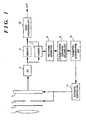
- FIG. 1 is a block diagram illustrating a configuration of an image sensing apparatus according to a first embodiment of the present invention. Referring to Fig. 1, flow of image data and image sensing operation will be described.
- An image of a scene passes through a lens 1, an optical low-pass filter 2, and an iris diaphragm 3, and is formed on photo sensing surface of CCD 4.
- the iris diaphragm 3 and an exposure period of the CCD 4 are controlled by an exposure controller 11 on the basis of data from a photometer (not shown) so that the CCD 4 is properly exposed.
- Analog image data of the first image (standard image) formed on the CCD 4 by sensing the scene in the proper exposure (first exposure) is converted into digital image data by an analog-digital (A/D) converter 5, and stored in a memory 7.
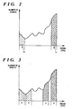
- the digital image data stored in the memory 7 is sent to a histogram generator 8 where a histogram of the number of event of signal levels of the standard image data, as shown in Fig. 2, is generated.
- a dynamic range expansion deciding unit 9 decides whether a dynamic range expansion processing is to be performed or not on the basis of the generated histogram. This decision is made in accordance with the total numbers of events of signal levels of the standard image data in different ranges A and B which are in high-end and low-end regions of the dynamic range of the image sensing apparatus, and predetermined thresholds of the numbers of events, TA and TB. For example, let the central values of the ranges A and B, LA and LB, respectively, have relationship LA ⁇ LB, and let the total numbers of the events of signal levels in the ranges A and B be HA and HB, respectively. Then, if the following condition 1 is satisfied, it is decided that the dynamic range expansion processing is not performed. HA ⁇ TA and HB ⁇ TB
- the parameter determination unit 10 determines parameters, i.e., a value for the iris diaphragm and an electronic shutter speed, for sensing the second image as a non-standard image in the second exposure on the basis of the histogram generated by the histogram generator 8.
- the electronic shutter speed for sensing a non-standard image (the second image) is determined so that an exposure period in the second image sensing operation is shorter than the exposure period when the standard image is sensed.
- the electronic shutter speed is determined so that the exposure period for sensing the non-standard image is longer than the exposure period for sensing the standard image so as to adjust the exposure period to the dark part of the standard image.
- Table 1 shows ratios of the electronic shutter speed, used for sensing a non-standard image, with respect to the shutter speed used for sensing the standard image in the first embodiment.
- the electronic shutter speed is determined on the basis of the larger value of SA and SB by referring to the table 1. For example, in a case where the condition 4 is satisfied and 1 ⁇ SA ⁇ 2 and 2 ⁇ SB ⁇ 3, since SB is larger than SA, the electronic shutter speed is determined on the basis of SB. From the table 1, the electronic shutter speed for sensing a non-standard image is determined as 1/4 of the shutter speed when the standard image is sensed.
- a non-standard image is sensed and processed with the standard image.
- a plurality of electronic shutter speed can be determined on the basis of both SA and SB. For example, if 1 ⁇ SA ⁇ 2 and 2 ⁇ SB ⁇ 3, then the first electrical shutter speed for sensing the first non-standard image can be decided on the basis of SA and is twice as fast as the shutter speed used for sensing the standard image, and the second electrical shutter speed for sensing the second non-standard image can be determined on the basis of SB and is 1/4 of the shutter speed used for sensing the standard image.
- the value for the iris diaphragm and the determined shutter speed for sensing a non-standard image is sent to the exposure controller 11 which controls the iris diaphragm 3 and the CCD 4, and a non-standard image is obtained.
- the image data of the non-standard image is analog-digital converted, and the converted image data is stored in a memory 6.
- the image data stored in the memory 6 and the image data stored in the memory 7 are sent to the image processing unit 12 where these two sets of data are processed and made into a single image with a widened dynamic range.
- Fig. 4 is a block diagram illustrating a configuration of the image processing unit 12 according to the first embodiment of the present invention.
- reference numeral 51 denotes a luminance level adjusting unit for changing the luminance level of the non-standard image to match to the luminance level of the standard image; 52, a replacing area determination unit for determining an area to be replaced in the standard image by a corresponding area of the level-adjusted non-standard image; and 53, a replacing unit for replacing the determined area of the standard image by the corresponding area of the non-standard image.
- the image sensing apparatus decides whether the dynamic range expansion processing is to be performed or not on the basis of the histogram of the signal levels of the standard image, however, a mode with which a user can make the aforesaid decision may be also provided in the image sensing apparatus.
- the electronic shutter speed is decided on the basis of the two ranges A and B in the histogram of the signal levels as shown in Fig. 2, however, the present invention is not limited to this.
- the shutter speed can be decided on the basis of more than two different ranges, A to D, as shown in Fig. 3, in the histogram of the signal levels.
- a mode for which a user can set a value for the iris diaphragm and a shutter speed for sensing a standard image and a non-standard image can be provided in the image sensing apparatus. It is also possible to change the values of the iris diaphragm by the parameter determination unit 10 for sensing a non-standard image.
- a standard image is sensed first, then it is determined whether the dynamic range expansion processing is to be performed or not on the basis of a histogram generated in accordance with the data of the sensed image, and a parameter to be used for sensing a second image is determined when the dynamic range expansion processing is determined to be processed.
- the image sensing apparatus automatically decides whether the dynamic range of the first image needs to be expanded or not, and, if it does, the image sensing apparatus senses the second image in an exposure which is adjusted to a bright area or a dark area, or senses two second images in exposures respectively adjusted to bright and dark areas.
- the image sensing apparatus processes the first image and the second image or images, thereby obtaining a single image with a widened dynamic range when the difference between luminance levels in bright and dark parts of a scene is very large. Further, it is determined that the dynamic range of the first image needs not to be expanded, the first image is directly outputted, thereby shortening time for an image sensing operation.
- the dynamic range expansion processing is performed by using a host computer 49 capable of controlling an image sensing apparatus 41.
- image data of an image sensed with a proper exposure (standard image) sensed by the image sensing apparatus 41 is transmitted to the host computer 49.
- the image data of the standard image is stored in a memory 44, and a histogram based on the stored image data is generated by a histogram generator 45, similarly to the first embodiment.
- the generated histogram is sent to a dynamic range expansion deciding unit 46 (referred as "deciding unit 46", hereinafter) which decides whether the dynamic range expansion processing is to be performed or not in accordance with the histogram.
- a parameter determination unit 47 determines a value for the iris diaphragm and an electrical shutter speed for sensing a non-standard image in accordance with the generated histogram, as in the first embodiment.
- the determined value for the iris diaphragm and the electrical shutter speed are transmitted via an interface 42 to the image sensing apparatus 41 which senses a non-standard image by using the transmitted parameters.
- Image data of the sensed non-standard image is sent the host computer 49 and stored in a memory 43.
- the image data of the standard image stored in the memory 44 and the image data of the non-standard image stored in the memory 43 are processed in the image processing unit 48, and made into a single image with a widened dynamic range.
- the obtained image may be outputted, or may be sent to the image sensing apparatus 41 and stored in a memory or a storage medium provided in the image sensing apparatus, in accordance with a user's choice.
- the image processing unit 48 has a configuration shown in Fig. 4, for example, as the image processing unit 12 in the first embodiment.
- an image with a widened dynamic range can be obtained, as in the first embodiment, by using an image sensing apparatus which does not have a dynamic range expansion function by connecting it to a host computer capable of performing the dynamic range expansion processing by processing images transmitted from the image sensing apparatus.
- the image sensing apparatus has a photometer, however, it is possible to apply the aforesaid configuration to an image sensing apparatus which does not have a photometer.
- an image to be analyzed for photometry is sensed first (pre-sensing operation), then by controlling an iris diaphragm and an electronic shutter on the basis of the result of the pre-sensing operation, a standard image can be obtained.
- the decision whether the dynamic range expansion processing is to be performed or not can be made by performing the above operation on the obtained standard image.
- Fig. 6 is a block diagram illustrating a configuration of an image sensing apparatus according to a second embodiment.
- reference numeral 61 denotes a lens; 62, an optical low-pass filter; 63, an image sensor such as CCD; 64, an analog-digital (A/D) converter; 65, an image processing unit; 66, a memory; and 67, an image sensor controller.
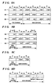
- Figs. 7A and 7B are explanatory charts for explaining sequences of controlling an image sensor 63 and exposures in the second embodiment.
- a pre-sensing operation for sensing a first image used for photometry is performed.
- signals in two interlaced fields of the image sensor 63 are outputted.
- One of the aforesaid two interlaced fields is called A field, and the other is called B field, hereinafter.
- the image data for photometry outputted from the image sensor 63 is converted into digital image data by the A/D converter 64, and inputted to the image processing unit 65 together with information on the exposure used for sensing the first image (first exposure).
- the image processing unit 65 decides an exposure to be used in the next image sensing operation by performing calculations based on the inputted digital image data and the first exposure, and sends a signal indicating the decided exposure to the image sensor controller 67.
- the image sensor controller 67 can control the image sensor 63 in the next image sensing operation in accordance with the decided exposure.
- the image data of the first image is stored in the memory 66.
- a main sensing operation is performed.
- the image sensor controller 67 controls the image sensor 63 so that the both images in the A and B fields are to be sensed in the proper exposure in the main sensing operation.
- the luminance distribution of the entire first image data obtained in the pre-sensing operation is analyzed. As the analyzed result, if the first image is found that it contains a relatively large dark area (73), images in the A and B fields are sensed in an over exposure in the main sensing operation.
- the first image is found that it contains a relatively large bright area (74), then images in the A and B fields are sensed in an under exposure in the main sensing operation. Further, if the luminance distribution of the first image shows a proper distribution (75), then an image in the A field is sensed in an over exposure and an image in the B field is sensed in an under exposure.
- the image data of the A and B fields, outputted from the image sensor 63 is stored in the memory 66 through the image processing unit 65, similarly to the first image sensed in the pre-sensing operation.
- the dynamic range expansion processing is performed without the image data obtained in the pre-sensing operation.
- the dynamic range expansion processing is not performed, and image data of a single image is made out of image data of two fields which are sensed in both the pre-sensing operation and the main sensing operation in the identical and proper exposure.
- the image data is converted into luminance signals and color difference signals and outputted.
- the dynamic range expansion processing when the dynamic range expansion processing is to be performed, first, a plurality of images are sensed in different exposures, then by processing image data of these sensed images, a single image with a widened dynamic range is made and outputted.
- a dynamic range expansion processing method methods disclosed in Japanese Patent Laid Open Nos. 7-135569 and 7-131799 or Japanese Patent Application Nos. 6-285067 and 6-285066 (USP 08/559,074), all of which are applied by the present applicant, can be used.
- Fig. 7B shows an example when only image data in the A field of the image sensor 63 is outputted in the pre-sensing operation so as to shorten time consumed in the overall image sensing operation.
- the pre-sensing operation of the A field is performed in an improper exposure (76 or 77)
- both the A and B fields are sensed in the proper exposure in the main sensing operation.
- the pre-sensing operation is performed in the proper exposure (78 ⁇ 80)
- the main sensing operation the A field is sensed in the proper exposure and the B field is sensed in either the proper, over or under exposure on the basis of the luminance distribution of the first image.
- Image data of the images sensed as above is transmitted to the image processing unit 65.
- a single image is made from image data of two fields sensed in the identical and proper exposure out of image data of the three fields sensed as above in different exposures. Further, in a case where the dynamic range expansion processing is to be performed, a single image with a widened dynamic range is made by processing the image data of the three fields.
- Figs. 8A to 8D are explanatory charts for explaining sequences of controlling the image sensor 63 according to a modification of the second embodiment.
- an image sensing apparatus used in this modification is the same as the one shown in Fig. 6.
- the feature of the image sensing apparatus of the modification is that image data of three kinds of images, respectively obtained by sensing in proper, over and under exposures, is used in the dynamic range expansion processing so as to cover a wide luminance range spread from a bright area to a dark area of a scene.
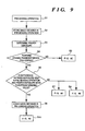
- Fig. 9 is a flowchart showing an operation of the image sensing apparatus according to the modification of the second embodiment.
- step S1 a pre-sensing operation is performed, then at step S2, an image. obtained in the pre-sensing operation (first image) is stored in the memory 66, and at step S3, a proper exposure is determined.
- step S4 whether the dynamic range expansion processing is to be performed or not is decided. When it is decided that the dynamic range expansion processing does not need to be performed, the A and B fields are sensed in an exposure shown in Fig. 8C in the main sensing operation at step S5.
- the exposure used in the pre-sensing operation (first exposure) is compared to the proper exposure at step S6, and if the difference between the two exposures is under a predetermined value, the scene is sensed in an exposure shown in Fig. 8A at step S7 or in an exposure shown in Fig. 8B at step S8 in the main sensing operation.
- image data of a single frame (consists of the A and B fields) is outputted from the image sensor 63 for photometry in the pre-sensing operation, thereafter, image data of two frames is outputted in the subsequent main sensing operations.
- the image data of the three frames obtained as above is processed as in the second embodiment to expand a dynamic range of the image sensing apparatus. Further, if the first image is sensed in an under exposure (82), image data of two frames are sensed in the proper and over exposures. Furthermore, if the first image is sensed in the proper exposure (83), image data of two frames are sensed in an over and under exposures.
- Fig. 8B shows an example to shorten time for the . overall image sensing operation by sensing an image of either the A or B field in the pre-sensing operation, and image data of three fields, including image data of improper exposure, are obtained in the main sensing operation.
- time to perform the overall image sensing operation is shorter by time for obtaining image data of two fields, comparing to the image sensing operation according to Fig. 8A.
- image data of the A (or B) field is obtained in the pre-sensing operation. If the pre-sensing operation was performed in an over exposure (84), image data of both the A and B fields is obtained in the proper exposure, then image data of the B (or A) field is obtained in an under exposure.
- the first exposure is compared to the proper exposure, and if it is determined at step S6 that the difference between the exposures is over a predetermined value, since it is not proper to use the first image data in the dynamic range expansion processing (the first image is too bright or too dark), the image data stored in the memory 66 is deleted at step S9. Thereafter, main sensing operations are performed in the exposures as shown in Fig. 8D at step S10. More specifically, in addition to a standard image (i.e., image sensed in the proper exposure), image data of at least one frame is newly sensed in an improper exposure, then by processing the image data of a plurality of frames, a single image with a widened dynamic range is obtained.
- a standard image i.e., image sensed in the proper exposure
- image data for photometry sensed in a pre-sensing operation is not wasted, a plurality of images necessary for the dynamic range expansion processing can be sensed in different exposures by performing the main sensing operations one time less than the conventional image sensing operation, and a single image with a widened dynamic range can be obtained by processing the plurality of sensed images.
- image data for photometry (first image) obtained in a pre-sensing operation and image data sensed in the proper or improper exposure decided in accordance with the first image is used in the dynamic range expansion processing. Therefore, the image data obtained in the pre-sensing operation is not wasted as well as overall image sensing time can be shortened. Especially, in the dynamic range expansion processing performed on the basis of two images sensed in the proper exposure and in the improper exposure, it becomes unnecessary to sense a third image in the main sensing operation.
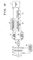
- Fig. 10 is a block diagram illustrating a configuration of an image sensing apparatus according to the third embodiment.
- reference numeral 101 denotes a lens
- 102 an iris diaphragm for adjusting an amount of incoming light
- 103 an optical low-pass filter
- 104 a solid-state image sensor such as CCD.
- reference numeral 105 denotes an exposure controller for controlling an exposure decided by the value of the iris diaphragm 102 and shutter speed of the solid-state image sensor 104.
- Reference numeral 106 denotes an A/D converter for converting image data outputted from the solid-state image sensor 104 to digital image data; and 107 and 108 are frame memories for temporarily storing digital image data of a single frame.
- Reference numeral 109 denotes a replacing area determination unit for determining areas which is to be processed with dynamic range expansion processing (i.e., bright or dark areas in the image); 110, a compression unit for compressing either image data of a reference image or of an image other than the reference image (non-reference image) which will be explained later, stored in the frame memory 107 or 108; and 111, an storage unit for storing the image data of the reference image and the non-reference image.
- dynamic range expansion processing i.e., bright or dark areas in the image
- 110 a compression unit for compressing either image data of a reference image or of an image other than the reference image (non-reference image) which will be explained later, stored in the frame memory 107 or 108; and 111, an storage unit for storing the image data of the reference image and the non-reference image.
- an image of an scene passes through the lens 101, the iris diaphragm 102, and the optical low-pass filter 103, and is formed on a photo sensing surface of the solid-state image sensor 104.
- the exposure controller 105 controls the iris diaphragm 102 and the solid-state image sensor 104 so that a single scene is sensed a plurality of times in different exposures.
- a plurality of images of the scene each of which is formed on the solid-state image sensor 104 in each image sensing operation are photo-electric converted and outputted as image data, and further analog-digital converted by the A/D converter 106. Then the digital image data of the plurality of images obtained as above is temporarily stored in the frame memories 107 and 108.
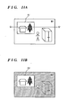
- Figs. 11A and 11B Examples of images sensed by the solid-state image sensor 104 are shown in Figs. 11A and 11B.
- Figs. 11A and 11B are two images obtained by sensing an identical scene of the inside of a room having a window in different exposures.
- Fig. 11A shows an image obtained by sensing the room so that the area B1 (inside of the room) is sensed in the proper exposure.
- the area A1 outside scenery through the window
- the dynamic range of the solid-state image sensor 104 is too narrow to properly express the both areas.
- the area B1 inside of the room
- the most brightest part of the area A1 outside scenery through the window
- the corresponding part of the solid-state image sensor 104 is saturated and the parts are expressed in white.
- Fig. 11B is an image obtained by sensing the identical scene in a low exposure so that the scenery of the outside of the room is not expressed in white.
- the area A2 outside scenery through the window
- the area B2 inside of the room
- image data shown in Fig. 11A is stored in the frame memory 107 and image data in Fig. 11B is stored in the frame memory 108, and letting the image data stored in the frame memory 107 be of a reference image, and the image data stored in the frame memory 108 be of a non-reference image.
- the replacing area determination unit 109 determines image data of an area which needs to be processed with the dynamic range expansion processing.
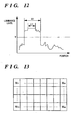
- Fig. 12 is a graph showing luminance levels of the reference image data shown in Fig. 11A with respect to a horizontal line, e.g., the line Q-Q'.
- the solid-state image sensor 104 corresponding to the most brightest part (C1) is saturated.
- the determination unit 109 determines an area whose luminance level is over a predetermined threshold T so as to extract bright areas where the solid-state image sensor 104 is saturated and the dynamic range expansion is necessary in the reference image. Then, the area A2 in the non-reference image corresponding to the determined area A1 in the reference image is determined as the area which needs to be processed with the dynamic range expansion processing.
- the compression unit 110 picks up the image data of the area A2 determined by the determination unit 109 out of the entire image data of the non-reference image, compresses the picked image data to generate compressed data.
- the storage unit 111 stores the image data of the reference image and the compressed data as necessary data for the dynamic range expansion processing.
- information on exposure conditions values of the iris diaphragm and shutter speed
- information on the picked image data e.g., a position of the picked-up area from the non-reference image
- the determination unit 109 finds an area, w ij (1 ⁇ i ⁇ n, 1 ⁇ j ⁇ m), including more than a predetermined number of pixels whose luminance levels are over a predetermined value, and determines that the area is needed to be performed with the dynamic range expansion processing.
- the image shown in Fig. 11A is dealt with as the reference image and the image shown in Fig. 11B is dealt with as the non-reference image.
- the image shown in Fig. 11B is dealt with as the reference image and the image shown in Fig. 11A as the non-reference image in the aforesaid dynamic range expansion processing.
- the third embodiment does not have to store entire image data of a plurality of sensed images, and image data of a reference image and compressed data, in a non-reference image, obtained by compressing picked image data of an area corresponding to an area, in the reference image, which needs to be processed with the dynamic range expansion processing. Therefore, it is possible to greatly reduce an amount of data to be stored as necessary data for the dynamic range expansion processing. In this case, since only a part of image data of the non-reference image is compressed and stored, an amount of data to be stored is reduced comparing to the case of compressing the entire image data of the non-reference image.
- reference numeral 112 denotes a reference image data compression unit for compressing image data of a reference image.
- compressed reference image data generated by compressing the data of the reference image with the reference image data compression unit 112 is stored. Accordingly, it is possible to further reduce an amount of data to be stored as necessary data for dynamic range expansion processing.
- the present invention is not limited to this.
- an image sensed in a proper exposure (standard image) be a reference image
- a single image with a widened dynamic range is produced, since it does not have to reproduce the standard image from compressed data, it is easy to process data of a plurality of images to form a single image.
- an area which is necessary for dynamic range expansion processing is picked up from a non-reference image and compressed data of the picked-up area is generated, then the compressed data and the image data of the reference image are stored as data necessary for the dynamic range expansion processing, however, the present invention is not limited to this.
- the image data picked up from the non-reference image may be stored without being compressed, or image data of areas which need to be processed with the dynamic range expansion processing in both the reference and non-reference images may be picked up and stored after being compressed or uncompressed. In either case, it is possible to reduce an amount of data to be stored for the dynamic range expansion processing than usual.
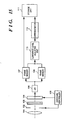
- Fig. 15 is a block diagram illustrating a configuration of an image sensing apparatus according to the second modification of the third embodiment, and the same unit and elements as those in Fig. 10 are referred by the same reference numerals and explanations of those are omitted.
- reference numeral 113 denotes a luminance level adjusting unit for adjusting the luminance levels of a reference image and a non-reference image. Further, reference numeral 114 denotes a differentiator for generating differential data for each pixel from image data stored in the frame memory 107 and image data stored in the frame memory 108.
- the luminance level adjusting unit 113 adjusts luminance levels of the reference image stored in the frame memory 107 and the non-reference image stored in the frame memory 108. Thereafter, the differentiator 114 generates the differential data, i.e., compressed data, for each pixel from corresponding pixels of the reference image and the non-reference image.
- the non-reference image is sensed in half of the exposure used to sense the reference image, and if the luminance level of the area B2 (inside of the room) in the non-reference image shown in Fig. 11B is half of the luminance level of the area B1 (inside of the room) in the reference image, then the luminance level of the image data of the non-reference image is doubled by the luminance level adjusting unit 113, then differential data for each pixel is generated by the differentiator 114.
- the image data of the reference image and the above compressed data as necessary data for the dynamic range expansion processing is stored in a not-shown storage medium by the storage unit 111.
- information on exposure conditions (values of the iris diaphragm and shutter speed) for sensing the reference image and the non-reference image, and information on a condition for level adjusting for generating the differential data, and the like, are also stored with the compressed data.
- the image data of all the plurality of images necessary for the dynamic range expansion processing is not stored, but image data of a single reference image and compressed data generated from the difference between the reference image and a non-reference image is stored, thereby greatly reducing the amount of data to be stored for the dynamic range expansion processing.
- differential data is generated after luminance levels of a reference image and a non-reference image are adjusted, thus it is possible to greatly increase data compression ratio comparing to a case of generating the differential data without adjusting luminance levels of the reference image and the non-reference image.
- the present invention can be applied to a system constituted by a plurality of devices, or to an apparatus comprising a single device. Furthermore the invention is applicable also to a case where the object of the invention is attained by supplying a program to a system or apparatus.
Landscapes
- Engineering & Computer Science (AREA)
- Multimedia (AREA)
- Signal Processing (AREA)
- Studio Devices (AREA)
- Transforming Light Signals Into Electric Signals (AREA)
- Facsimile Image Signal Circuits (AREA)
- Photometry And Measurement Of Optical Pulse Characteristics (AREA)
Claims (15)
- Vorrichtung zur Bildverarbeitung, die in der Lage ist, ein Bildabtastmittel (41) zu steuern und die vom Abtastmittel abgetasteten Stehbilder verarbeitet, gekennzeichnet durch die Ausstattung mit:wobei bei Entscheiden des Entscheidungsmittels, daß die dynamische Bereichserweiterungsverarbeitung nicht auszuführen ist, das erste Bild ohne Zusammensetzen mit einem anderen Bild zur Ausgabe kommt.einem Histogrammerzeugungsmittel (8, 45) zum Erzeugen eines Histogramms von Signalpegeln eines ersten Stehbildes eines in einer ersten Belichtung vom Bildabtastmittel abgetasteten Gegenstands;einem Entscheidungsmittel (9, 46), das entscheidet, ob eine dynamische Bereichserweiterungsverarbeitung auf der Grundlage des vom Histogrammerzeugungsmittel erzeugten Histogramms auszuführen ist;einem Parameterbestimmungsmittel (10, 47), das Belichtungsparameter bestimmt, die vom Bildabtastmittel zum Abtasten eines zweiten Bildes eines Gegenstands in einer zweiten Belichtung zu verwenden sind, die sich von der ersten Belichtung unterscheidet, wenn das Entscheidungsmittel entscheidet, daß die dynamische Bereichserweiterungsverarbeitung auszuführen ist, auf der Grundlage des vom Histogrammerzeugungsmittel erzeugten Histogramms;einem Steuermittel (11, 47, 42), das, wenn das Entscheidungsmittel entscheidet, daß die dynamische Bereichserweiterungsverarbeitung auszuführen ist, das Bildabtastmittel steuert, einerseits das zweite Stehbild des Gegenstands unter Verwendung der vom Parameterbestimmungsmittel bestimmten Belichtungsparameter abzutasten, und andrerseits das Bildabtastmittel, kein anderes Bild des anderweitigen Gegenstands abzutasten; und miteinem Bildzusammensetzmittel (12, 48), das beim Abtasten des zweiten Bildes das erste Bild und das zweite Bild zusammensetzt, um ein einziges Bild des Gegenstands mit einem aufgeweiteten Dynamikbereich zu erzeugen,
- Vorrichtung nach Anspruch 1, bei der das Parameterentscheidungsmittel (10, 47) eingerichtet ist zum Bestimmen von Belichtungsparametern zum Einstellen einer Vielzahl von Belichtungsbedingungen, die vom Bildabtastmittel zum Abtasten einer Vielzahl von Bildern des Gegenstands mit den Belichtungsbedingungen anzuwenden sind, die sich von der ersten Belichtung und von anderen unterscheiden, und wobei das Bildzusammensetzmittel (12, 48) eingerichtet ist, das erste Bild und die Vielzahl von in der Vielzahl von Belichtungsbedingungen abgetasteten Bildern zusammenzusetzen, um ein Einzelbild des Gegenstands zu erzeugen.
- Vorrichtung nach Anspruch 1 oder 2, deren Entscheidungsmittel (9, 46) eingerichtet ist zu entscheiden, ob eine dynamische Bereichserweiterung durch Vergleichen wenigstens einer Gesamtzahl von Ereignissen auszuführen ist, die wenigstens in einem vorbestimmten Bereich von Signalpegeln im Histogramm mit dem vorbestimmten Schwellwert aufgetreten sind.
- Vorrichtung nach einem der vorstehenden Ansprüche, mit einem Modus, in dem ein Anwender Möglichkeit zum Bestimmen hat, ob die dynamische Bereichserweiterungsverarbeitung auszuführen ist, und das Bestimmen vom Bestimmungsmittel gegenüber der Entscheidung des Entscheidungsmittels priorisiert ist.
- Vorrichtung nach einem der vorstehenden Ansprüche, bei der das Parameterbestimmungsmittel (10, 47) eingerichtet ist zum Bestimmen, daß eine Anzahl von Bildern, die größer ist als zwei, mit unterschiedlichen Belichtungsbedingungen auf der Grundlage der Signalpegel des vom Histogrammerzeugungsmittel erzeugten Histogramms abzutasten ist.
- Vorrichtung nach Anspruch 5, bei der ein Anwender in der Lage ist, die Anzahl von mit unterschiedlichen Belichtungsbedingungen abzutastenden Bildern einzustellen.
- Vorrichtung nach Anspruch 6, bei der unterschiedliche Belichtungsbedingungen Über- und Unterbelichtungen in Hinsicht auf das erste Bild umfassen.
- Vorrichtung nach einem der vorstehenden Ansprüche in Verbindung mit einem Bildabtastmittel.
- Verfahren zur Bildabtastung, gekennzeichnet durch die Verfahrensschritte:wobei bei Entscheiden im Entscheidungsschritt, daß die dynamische Bereichserweiterungsverarbeitung nicht auszuführen ist, Abgeben des ersten Bildes ohne Zusammensetzen mit einem anderen Bild erfolgt.erstes Abtasten eines ersten Stehbildes von einem Gegenstand in einer ersten Belichtung durch ein Bildabtastmittel;Erzeugen eines Histogramms von Signalpegeln des ersten Bildes;Entscheiden, ob eine dynamische Bereichserweiterungsverarbeitung auf der Grundlage des vom Histogrammerzeugungsschritt erzeugten Histogramms auszuführen ist;Bestimmen von Belichtungsparametern, die vom Bildabtastmittel zu verwenden sind zum Abtasten eines zweiten Stehbildes des Gegenstands in einer zweiten Belichtung, die sich von der ersten Belichtung auf der Grundlage des im Histogrammerzeugungsschritt erzeugten Histogramms unterscheidet, wenn das Entscheidungsmittel entscheidet, daß die dynamische Bereichserweiterungsverarbeitung auszuführen ist;Steuern des Bildabtastmittels zum Abtasten des zweiten Bildes vom Gegenstand unter Verwendung der im Parameterbestimmungsschritt bestimmten Belichtungsparameter, wenn die dynamische Bereichserweiterungsverarbeitung im Entscheidungsschritt auszuführen ist, und Steuern des Bildabtastmittels, kein anderes Bild des Gegenstands anderweitig abzutasten;Zusammensetzen des ersten Bildes mit dem zweiten Bild, um ein Einzelbild des Gegenstands mit einem aufgeweiteten Dynamikbereich beim Abtasten des zweiten Bildes zu erzeugen,
- Verfahren nach Anspruch 9, bei dem im Parameterbestimmungsschritt Belichtungsparameter zum Einstellen einer Vielzahl von Belichtungsbedingungen, zu verwenden vom Bildabtastmittel zum Abtasten einer Vielzahl von Bildern des Gegenstands mit Belichtungsbedingungen, die sich von denen der ersten Belichtung unterscheiden, bestimmt werden, und wobei das erste Bild und die Vielzahl der in der Vielzahl von Belichtungsbedingungen abgetasteten Bilder einen Zusammensetzschritt erfahren, um ein Einzelbild des Gegenstands zu erzeugen.
- Verfahren nach Anspruch 9 oder 10, bei dem der Entscheidungsschritt entscheidet, ob die dynamische Bereichserweiterungsverarbeitung durch Vergleichen wenigstens einer Gesamtzahl von Ereignissen auszuführen ist, die wenigstens in einem vorbestimmten Bereich der Signalpegel im Histogramm gegenüber einem vorbestimmten Schwellwert aufgetreten sind.
- Verfahren nach einem der Ansprüche 9 bis 11, mit einem Modus, in dem ein Anwender bestimmen kann, ob die dynamische Bereichserweiterungsverarbeitung auszuführen ist, wobei die Bestimmung des Bestimmungsmittels gegenüber der Entscheidung im Entscheidungsschritt priorisiert ist.
- Verfahren nach einem der Ansprüche 9 bis 12, das bestimmt, daß eine Anzahl von Bildern, die größer als zwei ist, mit unterschiedlichen Belichtungsparametern auf der Grundlage der Signalpegel des im Histogrammerzeugungsschritt erzeugten Histogramms abzutasten sind.
- Verfahren nach Anspruch 13, bei dem ein Anwender die Anzahl von abzutastenden Bildern mit unterschiedlichen Belichtungsbedingungen einstellt.
- Verfahren nach Anspruch 13 oder 14, bei dem die unterschiedlichen Belichtungsbedingungen Über- und Unterbelichtungen in Hinsicht auf das erste Bild umfassen.
Applications Claiming Priority (9)
| Application Number | Priority Date | Filing Date | Title |
|---|---|---|---|
| JP16924/95 | 1995-02-03 | ||
| JP01692495A JP3639627B2 (ja) | 1995-02-03 | 1995-02-03 | 画像合成装置 |
| JP1692495 | 1995-02-03 | ||
| JP7058794A JPH08256303A (ja) | 1995-03-17 | 1995-03-17 | 画像処理装置 |
| JP5879495 | 1995-03-17 | ||
| JP58794/95 | 1995-03-17 | ||
| JP26317695 | 1995-10-11 | ||
| JP263176/95 | 1995-10-11 | ||
| JP7263176A JPH09107499A (ja) | 1995-10-11 | 1995-10-11 | 撮像装置及びその画像処理方法 |
Publications (3)
| Publication Number | Publication Date |
|---|---|
| EP0725536A2 EP0725536A2 (de) | 1996-08-07 |
| EP0725536A3 EP0725536A3 (de) | 1997-05-28 |
| EP0725536B1 true EP0725536B1 (de) | 2003-04-16 |
Family
ID=27281618
Family Applications (1)
| Application Number | Title | Priority Date | Filing Date |
|---|---|---|---|
| EP96300690A Expired - Lifetime EP0725536B1 (de) | 1995-02-03 | 1996-01-31 | Verfahren und Vorrichtung zur Bildabtastung mit Dynamikumfangserweiterung |
Country Status (4)
| Country | Link |
|---|---|
| US (1) | US5929908A (de) |
| EP (1) | EP0725536B1 (de) |
| DE (1) | DE69627407T2 (de) |
| ES (1) | ES2193226T3 (de) |
Families Citing this family (86)
| Publication number | Priority date | Publication date | Assignee | Title |
|---|---|---|---|---|
| IL117311A0 (en) * | 1996-02-28 | 1996-06-18 | Driver Safety Systems Ltd | System for photographing moving vehicles |
| US6151073A (en) * | 1996-03-28 | 2000-11-21 | Fotonation, Inc. | Intelligent camera flash system |
| US6219097B1 (en) * | 1996-05-08 | 2001-04-17 | Olympus Optical Co., Ltd. | Image pickup with expanded dynamic range where the first exposure is adjustable and second exposure is predetermined |
| DE19880174D2 (de) * | 1997-02-21 | 2000-01-05 | Rolf Eckmiller | Lernfähiges aktives Kamerasystem |
| FI103627B1 (fi) * | 1997-06-12 | 1999-07-30 | Finnelpro Oy | Digitointilaite |
| JP3222803B2 (ja) * | 1997-06-16 | 2001-10-29 | 旭光学工業株式会社 | 画像読取装置 |
| KR100246358B1 (ko) * | 1997-09-25 | 2000-03-15 | 김영환 | 전자셔터를 구비한 액티브 픽셀 센서 |
| JP4282113B2 (ja) * | 1998-07-24 | 2009-06-17 | オリンパス株式会社 | 撮像装置および撮像方法、並びに、撮像プログラムを記録した記録媒体 |
| JP2000050151A (ja) | 1998-07-28 | 2000-02-18 | Olympus Optical Co Ltd | 撮像装置 |
| JP2000069251A (ja) * | 1998-08-26 | 2000-03-03 | Asahi Optical Co Ltd | 画像読取装置の露光制御装置 |
| JP4245699B2 (ja) | 1998-09-16 | 2009-03-25 | オリンパス株式会社 | 撮像装置 |
| US6930710B1 (en) * | 1998-11-13 | 2005-08-16 | Cnh Canada, Ltd. | Method of and apparatus for processing a video image |
| JP2000224470A (ja) * | 1999-02-02 | 2000-08-11 | Minolta Co Ltd | カメラシステム |
| US6967680B1 (en) * | 1999-05-28 | 2005-11-22 | Microsoft Corporation | Method and apparatus for capturing images |
| KR100363826B1 (ko) * | 1999-06-07 | 2002-12-06 | 히다치덴시 가부시키가이샤 | 넓은 다이내믹레인지의 영상신호를 생성하는텔레비젼신호처리장치와 그 신호처리장치를 가지는텔레비젼카메라 및 텔레비젼신호처리방법 |
| US7428011B1 (en) * | 1999-09-02 | 2008-09-23 | Fujifilm Corporation | Wide dynamic range electronic image recording and reproducing system |
| TW469733B (en) * | 2000-01-07 | 2001-12-21 | Dynacolor Inc | Method of dynamically modulating image brightness and image catching device using the method |
| JP2001268326A (ja) * | 2000-03-23 | 2001-09-28 | Minolta Co Ltd | 画像処理装置および撮像装置 |
| US7342609B2 (en) * | 2000-05-09 | 2008-03-11 | Eastman Kodak Company | Exposure adjustment in an imaging apparatus |
| US6946635B1 (en) * | 2000-10-05 | 2005-09-20 | Ess Technology, Inc. | System for improving the dynamic range of solid-state imaging devices |
| US7298402B2 (en) * | 2000-10-26 | 2007-11-20 | Olympus Corporation | Image-pickup apparatus with expanded dynamic range capabilities |
| US6958778B2 (en) | 2000-11-21 | 2005-10-25 | Hitachi Kokusai Electric Inc. | Iris control method and apparatus for television camera for controlling iris of lens according to video signal, and television camera using the same |
| CN1316814C (zh) * | 2001-03-16 | 2007-05-16 | 幻影自动化机械公司 | 增大图像传感器有效动态范围的系统和方法 |
| AU2002331688A1 (en) * | 2001-08-24 | 2003-03-10 | Dialog Semiconductor Gmbh | Fully integrated solid state imager and camera circuitry |
| US20030076408A1 (en) * | 2001-10-18 | 2003-04-24 | Nokia Corporation | Method and handheld device for obtaining an image of an object by combining a plurality of images |
| US8054357B2 (en) * | 2001-11-06 | 2011-11-08 | Candela Microsystems, Inc. | Image sensor with time overlapping image output |
| US6795117B2 (en) | 2001-11-06 | 2004-09-21 | Candela Microsystems, Inc. | CMOS image sensor with noise cancellation |
| US7233350B2 (en) * | 2002-01-05 | 2007-06-19 | Candela Microsystems, Inc. | Image sensor with interleaved image output |
| US6859230B2 (en) * | 2001-11-07 | 2005-02-22 | Omnivision Technologies, Inc. | Method of fast automatic exposure or gain control in a MOS image sensor |
| JP3927995B2 (ja) | 2001-12-27 | 2007-06-13 | ソニー株式会社 | 画像表示制御装置と画像表示制御方法及び撮像装置 |
| US20030193594A1 (en) * | 2002-04-16 | 2003-10-16 | Tay Hiok Nam | Image sensor with processor controlled integration time |
| AT412317B (de) * | 2002-05-06 | 2004-12-27 | Advanced Comp Vision Gmbh Acv | Verfahren und einrichtung zum ausgleich sich verändernder lichtverhältnisse bei der aufnahme von videobildsequenzen |
| US20040008267A1 (en) * | 2002-07-11 | 2004-01-15 | Eastman Kodak Company | Method and apparatus for generating images used in extended range image composition |
| JP2004048561A (ja) * | 2002-07-15 | 2004-02-12 | Fuji Photo Film Co Ltd | 撮像装置及び測光装置 |
| US20040100565A1 (en) * | 2002-11-22 | 2004-05-27 | Eastman Kodak Company | Method and system for generating images used in extended range panorama composition |
| JP2004248061A (ja) * | 2003-02-14 | 2004-09-02 | Fuji Photo Film Co Ltd | 画像処理装置、方法及びプログラム |
| DE10307744A1 (de) * | 2003-02-24 | 2004-09-02 | Carl Zeiss Jena Gmbh | Verfahren zur Bestimmung der Intensitätswerte elektromagnetischer Strahlung |
| US7015960B2 (en) * | 2003-03-18 | 2006-03-21 | Candela Microsystems, Inc. | Image sensor that uses a temperature sensor to compensate for dark current |
| US6879731B2 (en) * | 2003-04-29 | 2005-04-12 | Microsoft Corporation | System and process for generating high dynamic range video |
| US7317843B2 (en) * | 2004-04-01 | 2008-01-08 | Microsoft Corporation | Luminance correction |
| US7463296B2 (en) | 2004-04-01 | 2008-12-09 | Microsoft Corporation | Digital cameras with luminance correction |
| US20050270397A1 (en) * | 2004-06-02 | 2005-12-08 | Battles Amy E | System and method for indicating settings |
| JP2006033049A (ja) * | 2004-07-12 | 2006-02-02 | Konica Minolta Photo Imaging Inc | 撮像装置 |
| US7561731B2 (en) * | 2004-12-27 | 2009-07-14 | Trw Automotive U.S. Llc | Method and apparatus for enhancing the dynamic range of a stereo vision system |
| JP4838302B2 (ja) * | 2005-05-10 | 2011-12-14 | アクティブ オプティクス ピーティーワイ リミテッド | 画像取り込みシステムを制御する方法、画像取り込みシステム、および、デジタルカメラ |
| JP4607006B2 (ja) * | 2005-12-27 | 2011-01-05 | 京セラ株式会社 | 映像信号処理方法および映像信号処理装置 |
| US7903168B2 (en) * | 2006-04-06 | 2011-03-08 | Eastman Kodak Company | Camera and method with additional evaluation image capture based on scene brightness changes |
| JP2007318724A (ja) * | 2006-04-25 | 2007-12-06 | Matsushita Electric Ind Co Ltd | 固体撮像装置の駆動方法、及び固体撮像装置 |
| TW200820123A (en) * | 2006-10-20 | 2008-05-01 | Primax Electronics Ltd | Method and system of generating high dynamic range image corresponding to specific scene |
| US20080198235A1 (en) * | 2007-02-16 | 2008-08-21 | Shou-Lung Chen | High dynamic range image recorder |
| JP4306750B2 (ja) | 2007-03-14 | 2009-08-05 | ソニー株式会社 | 撮像装置、撮像方法、露光制御方法、プログラム |
| US8264594B2 (en) * | 2007-07-25 | 2012-09-11 | Candela Microsystems (S) Pte. Ltd. | Exposure control for an imaging system |
| US7961398B2 (en) * | 2008-03-05 | 2011-06-14 | Contrast Optical Design & Engineering, Inc. | Multiple image camera and lens system |
| US7999861B2 (en) * | 2008-03-14 | 2011-08-16 | Omron Corporation | Image processing apparatus for generating composite image with luminance range optimized for a designated area |
| EP2265993B8 (de) * | 2008-03-28 | 2021-07-07 | Contrast, Inc. | Ganzstrahl-bildaufteilungssystem |
| JP5271631B2 (ja) * | 2008-08-07 | 2013-08-21 | Hoya株式会社 | 画像処理ユニット、撮像装置、合成画像作成プログラム |
| EP2476021B1 (de) * | 2009-09-10 | 2019-11-20 | Contrast, Inc. | System zur teilung vollständiger strahlungsbilder |
| JP2011091584A (ja) * | 2009-10-21 | 2011-05-06 | Seiko Epson Corp | 撮像装置、撮像方法及び電子機器 |
| KR20110043833A (ko) * | 2009-10-22 | 2011-04-28 | 삼성전자주식회사 | 퍼지룰을 이용한 디지털 카메라의 다이나믹 레인지 확장모드 결정 방법 및 장치 |
| KR101633893B1 (ko) * | 2010-01-15 | 2016-06-28 | 삼성전자주식회사 | 다중노출 영상을 합성하는 영상합성장치 및 방법 |
| KR101665511B1 (ko) * | 2010-02-11 | 2016-10-12 | 삼성전자 주식회사 | 광역 역광 보정 하드웨어 장치 및 이를 포함하는 촬영 장치 |
| TWI468009B (zh) | 2010-08-23 | 2015-01-01 | Red Com Inc | 高動態範圍視頻 |
| US9584733B2 (en) * | 2010-09-30 | 2017-02-28 | Apple Inc. | High dynamic range transition |
| JP5683418B2 (ja) * | 2011-09-08 | 2015-03-11 | オリンパスイメージング株式会社 | 撮影機器及び撮影方法 |
| JP5898466B2 (ja) * | 2011-11-11 | 2016-04-06 | キヤノン株式会社 | 撮像装置、その制御方法、及びプログラム |
| JP6101896B2 (ja) * | 2012-01-11 | 2017-03-29 | ノーリツプレシジョン株式会社 | 画像処理プログラムおよび画像処理装置 |
| EP2635027A1 (de) * | 2012-03-01 | 2013-09-04 | Thomson Licensing | Verfahren und Vorrichtung zur Codierung eines Bildes mit erhöhter Präzision, Verfahren und Vorrichtung zur Wiederherstellung eines Bildes mit erhöhter Präzision |
| US9602735B2 (en) | 2012-12-19 | 2017-03-21 | International Business Machines Corporation | Digital imaging exposure metering system |
| CN103973988B (zh) * | 2013-01-24 | 2018-02-02 | 华为终端(东莞)有限公司 | 场景识别方法及装置 |
| JP6159105B2 (ja) * | 2013-03-06 | 2017-07-05 | キヤノン株式会社 | 撮像装置及びその制御方法 |
| US9955084B1 (en) | 2013-05-23 | 2018-04-24 | Oliver Markus Haynold | HDR video camera |
| CN105794203B (zh) * | 2013-12-04 | 2020-03-20 | 拉姆伯斯公司 | 高动态范围图像传感器 |
| JP2016006930A (ja) | 2014-06-20 | 2016-01-14 | ソニー株式会社 | 撮像装置および撮像方法 |
| US10277771B1 (en) | 2014-08-21 | 2019-04-30 | Oliver Markus Haynold | Floating-point camera |
| US10225485B1 (en) | 2014-10-12 | 2019-03-05 | Oliver Markus Haynold | Method and apparatus for accelerated tonemapping |
| WO2016165967A1 (en) * | 2015-04-14 | 2016-10-20 | Fotonation Limited | Image acquisition method and apparatus |
| US10264196B2 (en) | 2016-02-12 | 2019-04-16 | Contrast, Inc. | Systems and methods for HDR video capture with a mobile device |
| US10257394B2 (en) | 2016-02-12 | 2019-04-09 | Contrast, Inc. | Combined HDR/LDR video streaming |
| CA3033242A1 (en) | 2016-08-09 | 2018-02-15 | Contrast, Inc. | Real-time hdr video for vehicle control |
| US11265530B2 (en) | 2017-07-10 | 2022-03-01 | Contrast, Inc. | Stereoscopic camera |
| US10757320B2 (en) | 2017-12-28 | 2020-08-25 | Waymo Llc | Multiple operating modes to expand dynamic range |
| JP7075272B2 (ja) * | 2018-04-20 | 2022-05-25 | キヤノン株式会社 | 画像処理装置、情報表示装置、制御方法、及びプログラム |
| JP7075271B2 (ja) * | 2018-04-20 | 2022-05-25 | キヤノン株式会社 | 画像処理装置、情報表示装置、制御方法、及びプログラム |
| US10951888B2 (en) | 2018-06-04 | 2021-03-16 | Contrast, Inc. | Compressed high dynamic range video |
| US10924693B2 (en) * | 2018-06-19 | 2021-02-16 | Canon Kabushiki Kaisha | Image sensor and image capturing apparatus |
| CN112738411B (zh) * | 2020-12-29 | 2022-08-19 | 重庆紫光华山智安科技有限公司 | 曝光调节方法、装置、电子设备及存储介质 |
Family Cites Families (6)
| Publication number | Priority date | Publication date | Assignee | Title |
|---|---|---|---|---|
| JPS63306778A (ja) * | 1987-06-09 | 1988-12-14 | Canon Inc | 撮像装置 |
| US5162914A (en) * | 1987-06-09 | 1992-11-10 | Canon Kabushiki Kaisha | Image sensing device with diverse storage fumes used in picture composition |
| IL87306A0 (en) * | 1988-08-02 | 1989-01-31 | Technion Res & Dev Foundation | Wide dynamic range camera |
| JP3082971B2 (ja) * | 1991-08-30 | 2000-09-04 | 富士写真フイルム株式会社 | ビデオ・カメラ,それを用いた撮影方法およびその動作方法,ならびに画像処理装置および方法 |
| US5420635A (en) * | 1991-08-30 | 1995-05-30 | Fuji Photo Film Co., Ltd. | Video camera, imaging method using video camera, method of operating video camera, image processing apparatus and method, and solid-state electronic imaging device |
| JP3528184B2 (ja) * | 1991-10-31 | 2004-05-17 | ソニー株式会社 | 画像信号の輝度補正装置及び輝度補正方法 |
-
1996
- 1996-01-30 US US08/594,265 patent/US5929908A/en not_active Expired - Lifetime
- 1996-01-31 DE DE69627407T patent/DE69627407T2/de not_active Expired - Lifetime
- 1996-01-31 ES ES96300690T patent/ES2193226T3/es not_active Expired - Lifetime
- 1996-01-31 EP EP96300690A patent/EP0725536B1/de not_active Expired - Lifetime
Also Published As
| Publication number | Publication date |
|---|---|
| ES2193226T3 (es) | 2003-11-01 |
| US5929908A (en) | 1999-07-27 |
| DE69627407T2 (de) | 2004-01-08 |
| EP0725536A2 (de) | 1996-08-07 |
| DE69627407D1 (de) | 2003-05-22 |
| EP0725536A3 (de) | 1997-05-28 |
Similar Documents
| Publication | Publication Date | Title |
|---|---|---|
| EP0725536B1 (de) | Verfahren und Vorrichtung zur Bildabtastung mit Dynamikumfangserweiterung | |
| KR100968983B1 (ko) | 촬상 장치 | |
| KR101549529B1 (ko) | 촬상장치, 그 제어 방법, 및 기록 매체 | |
| JP4210021B2 (ja) | 画像信号処理装置および画像信号処理方法 | |
| US5801773A (en) | Image data processing apparatus for processing combined image signals in order to extend dynamic range | |
| US6204881B1 (en) | Image data processing apparatus which can combine a plurality of images at different exposures into an image with a wider dynamic range | |
| US7030911B1 (en) | Digital camera and exposure control method of digital camera | |
| JP4404823B2 (ja) | 撮像装置 | |
| US8081242B2 (en) | Imaging apparatus and imaging method | |
| JP2749921B2 (ja) | 撮像装置 | |
| US6583820B1 (en) | Controlling method and apparatus for an electronic camera | |
| JPH05191718A (ja) | 撮像装置 | |
| US20030081141A1 (en) | Brightness adjustment method | |
| JP2007124604A (ja) | 画像処理装置およびその処理方法 | |
| US7884866B2 (en) | Imaging apparatus and imaging method | |
| US5585848A (en) | Control of solid-state image sensor | |
| US8144216B2 (en) | Imaging apparatus and imaging method | |
| JP3645502B2 (ja) | 撮像装置及び映像信号処理方法 | |
| JP2002084449A (ja) | 固体撮像素子を用いた撮像装置 | |
| JP3420303B2 (ja) | 画像合成装置 | |
| JP2001268345A (ja) | 画像合成装置 | |
| JPH11155108A (ja) | 映像信号処理装置と処理方法、それを用いたビデオカメラ | |
| JP2002369074A (ja) | 光学機器の露出制御装置およびプログラム、並びに方法 | |
| CN111866399B (zh) | 图像处理设备、其控制方法以及计算机可读介质 | |
| JPH08205021A (ja) | 画像入力装置 |
Legal Events
| Date | Code | Title | Description |
|---|---|---|---|
| PUAI | Public reference made under article 153(3) epc to a published international application that has entered the european phase |
Free format text: ORIGINAL CODE: 0009012 |
|
| AK | Designated contracting states |
Kind code of ref document: A2 Designated state(s): DE ES FR GB IT NL |
|
| PUAL | Search report despatched |
Free format text: ORIGINAL CODE: 0009013 |
|
| AK | Designated contracting states |
Kind code of ref document: A3 Designated state(s): DE ES FR GB IT NL |
|
| 17P | Request for examination filed |
Effective date: 19971008 |
|
| 17Q | First examination report despatched |
Effective date: 19990825 |
|
| GRAG | Despatch of communication of intention to grant |
Free format text: ORIGINAL CODE: EPIDOS AGRA |
|
| GRAG | Despatch of communication of intention to grant |
Free format text: ORIGINAL CODE: EPIDOS AGRA |
|
| GRAH | Despatch of communication of intention to grant a patent |
Free format text: ORIGINAL CODE: EPIDOS IGRA |
|
| GRAH | Despatch of communication of intention to grant a patent |
Free format text: ORIGINAL CODE: EPIDOS IGRA |
|
| GRAA | (expected) grant |
Free format text: ORIGINAL CODE: 0009210 |
|
| AK | Designated contracting states |
Designated state(s): DE ES FR GB IT NL |
|
| REG | Reference to a national code |
Ref country code: GB Ref legal event code: FG4D |
|
| REF | Corresponds to: |
Ref document number: 69627407 Country of ref document: DE Date of ref document: 20030522 Kind code of ref document: P |
|
| REG | Reference to a national code |
Ref country code: ES Ref legal event code: FG2A Ref document number: 2193226 Country of ref document: ES Kind code of ref document: T3 |
|
| ET | Fr: translation filed | ||
| PLBE | No opposition filed within time limit |
Free format text: ORIGINAL CODE: 0009261 |
|
| STAA | Information on the status of an ep patent application or granted ep patent |
Free format text: STATUS: NO OPPOSITION FILED WITHIN TIME LIMIT |
|
| 26N | No opposition filed |
Effective date: 20040119 |
|
| PGFP | Annual fee paid to national office [announced via postgrant information from national office to epo] |
Ref country code: ES Payment date: 20081204 Year of fee payment: 14 |
|
| PGFP | Annual fee paid to national office [announced via postgrant information from national office to epo] |
Ref country code: NL Payment date: 20090120 Year of fee payment: 14 |
|
| PGFP | Annual fee paid to national office [announced via postgrant information from national office to epo] |
Ref country code: IT Payment date: 20090119 Year of fee payment: 14 |
|
| REG | Reference to a national code |
Ref country code: NL Ref legal event code: V1 Effective date: 20100801 |
|
| PG25 | Lapsed in a contracting state [announced via postgrant information from national office to epo] |
Ref country code: NL Free format text: LAPSE BECAUSE OF NON-PAYMENT OF DUE FEES Effective date: 20100801 |
|
| REG | Reference to a national code |
Ref country code: ES Ref legal event code: FD2A Effective date: 20110218 |
|
| PG25 | Lapsed in a contracting state [announced via postgrant information from national office to epo] |
Ref country code: IT Free format text: LAPSE BECAUSE OF NON-PAYMENT OF DUE FEES Effective date: 20100131 |
|
| PG25 | Lapsed in a contracting state [announced via postgrant information from national office to epo] |
Ref country code: ES Free format text: LAPSE BECAUSE OF NON-PAYMENT OF DUE FEES Effective date: 20110217 |
|
| PG25 | Lapsed in a contracting state [announced via postgrant information from national office to epo] |
Ref country code: ES Free format text: LAPSE BECAUSE OF NON-PAYMENT OF DUE FEES Effective date: 20100201 |
|
| PGFP | Annual fee paid to national office [announced via postgrant information from national office to epo] |
Ref country code: DE Payment date: 20140131 Year of fee payment: 19 |
|
| PGFP | Annual fee paid to national office [announced via postgrant information from national office to epo] |
Ref country code: FR Payment date: 20140124 Year of fee payment: 19 |
|
| PGFP | Annual fee paid to national office [announced via postgrant information from national office to epo] |
Ref country code: GB Payment date: 20140123 Year of fee payment: 19 |
|
| REG | Reference to a national code |
Ref country code: DE Ref legal event code: R119 Ref document number: 69627407 Country of ref document: DE |
|
| GBPC | Gb: european patent ceased through non-payment of renewal fee |
Effective date: 20150131 |
|
| PG25 | Lapsed in a contracting state [announced via postgrant information from national office to epo] |
Ref country code: DE Free format text: LAPSE BECAUSE OF NON-PAYMENT OF DUE FEES Effective date: 20150801 Ref country code: GB Free format text: LAPSE BECAUSE OF NON-PAYMENT OF DUE FEES Effective date: 20150131 |
|
| REG | Reference to a national code |
Ref country code: FR Ref legal event code: ST Effective date: 20150930 |
|
| PG25 | Lapsed in a contracting state [announced via postgrant information from national office to epo] |
Ref country code: FR Free format text: LAPSE BECAUSE OF NON-PAYMENT OF DUE FEES Effective date: 20150202 |