EP0725461A2 - Construction de connecteur ayant des leviers - Google Patents
Construction de connecteur ayant des leviers Download PDFInfo
- Publication number
- EP0725461A2 EP0725461A2 EP96104666A EP96104666A EP0725461A2 EP 0725461 A2 EP0725461 A2 EP 0725461A2 EP 96104666 A EP96104666 A EP 96104666A EP 96104666 A EP96104666 A EP 96104666A EP 0725461 A2 EP0725461 A2 EP 0725461A2
- Authority
- EP
- European Patent Office
- Prior art keywords
- lever
- slot
- arm
- connector housing
- spring
- Prior art date
- Legal status (The legal status is an assumption and is not a legal conclusion. Google has not performed a legal analysis and makes no representation as to the accuracy of the status listed.)
- Granted
Links
Images


Classifications
-
- H—ELECTRICITY
- H01—ELECTRIC ELEMENTS
- H01R—ELECTRICALLY-CONDUCTIVE CONNECTIONS; STRUCTURAL ASSOCIATIONS OF A PLURALITY OF MUTUALLY-INSULATED ELECTRICAL CONNECTING ELEMENTS; COUPLING DEVICES; CURRENT COLLECTORS
- H01R13/00—Details of coupling devices of the kinds covered by groups H01R12/70 or H01R24/00 - H01R33/00
- H01R13/62—Means for facilitating engagement or disengagement of coupling parts or for holding them in engagement
- H01R13/629—Additional means for facilitating engagement or disengagement of coupling parts, e.g. aligning or guiding means, levers, gas pressure electrical locking indicators, manufacturing tolerances
- H01R13/62933—Comprising exclusively pivoting lever
Definitions
- This invention relates to a lever type connector assembly which interconnects and separates connectors by utilizing a cam action and more particularly to a lever type connector assembly in which a torsion coil spring for rockably biasing a lever to a given initial position is temporarily attached to one of the connectors.
- a lever type connector assembly has an advantage of interconnecting and separating connectors by a small force and particularly can be applied to multipole connectors.
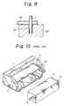
- Figure 10 is an exploded perspective view of a conventional lever type connector assembly.
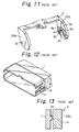
- Figure 11 is a perspective view of a lever shown in Figure 10, illustrating a torsion coil spring mounted on a side plate of the lever.
- Figure 12 is a perspective view of a female connector housing shown in Figure 10.
- Figure 13 is a fragmentary cross sectional view of the housing and lever shown in Figure 10, illustrating a position of which an end of the torsion coil spring engages with the housing.
- Figure 14 is a perspective view of a conventional torsion coil spring.
- Figure 15 is a fragmentary enlarged perspective view of the lever shown in Figure 11.
- Figure 16 is a cross sectional view of the lever shown in Figure 11, illustrating a process of attaching the torsion coil spring to the lever.
- Figure 17 is a longitudinal sectional view of the lever, illustrating a process of attaching an end of the torsion coil spring into a holding slot in the lever.
- An example of a conventional connector housing assembly includes one (female) connector housing 1, a lever 3 mounted rotatably on a pair of support axles 4 on the housing 1 and having cam grooves 3a, and the other (male) connector housing 2 having a pair of cam followers 5.
- the pair of connector housings 1 and 2 are coupled to and detached from each other when the lever 3 is turned about the axles 4 to move the cam followers 5.
- a torsion coil spring 6 shown in Figure 14 is coupled to the lever 3 and female connector housing 1, as shown in Figures 11 to 13.
- a ring portion 6a of the spring 6 ( Figure 14) is disposed around a bearing hole 3b and on an inner face of a side plate or arm 22a of the lever (see Figure 11), an end portion 6b of the spring 6 engages with the inner face of the arm 22a (see Figure 11), and the other end portion 6c of the spring 6 engages with a projection 1a on an outer face of the connector housing 1 (see Figures 12 and 13).
- the present applicant has proposed a lever type connector assembly in which the lever is provided with a pair of holding slots which accommodate opposite end portions of the torsion coil spring with it being biased, and in which one end portion of the spring accommodated in one holding slot is transferred from the slot to the connector housing after mounting the lever on the housing (Japanese Utility Model Public Disclosure No. 6-11270).
- Japanese Utility Model Public Disclosure No. 6-11270 Japanese Utility Model Public Disclosure No. 6-11270.
- the side plate 22a is provided in the inner face with a pair of holding slots 7 and 8 which receive opposite end portions 6b and 6c of the torsion coil spring 6 with the spring 6 being biased, as shown in Figures 15 and 16.
- one end portion 6b of the spring 6 is inserted into one holding slot 7 and the other end portion 6c is pushed and turned by a tool pin similar to an end of a ball pen to insert the end portion 6c into the other holding slot 8.
- a reference number 10 is a tool aperture through which the tool pin 9 passes so that it pushes the other end portion 6c of the spring 6 in the other holding slot 8 towards the projection 1a on the connector housing 1.
- An object of the present invention is to provide a lever type connector assembly in which a process of attaching a torsion coil spring to a lever beforehand can be simplified and an entire assembling work of connectors can be greatly improved.
- a lever type connector assembly in accordance with the present invention comprises: a pair of first and second connector housings; a lever having a pair of arms on opposite ends and mounted rotatably on said first connector housing, said arm being provided on its inner face with a cam groove which engages with a cam follower on said second connector housing, said first and second connector housings being connected with and detached from each other when said lever is turned to move said cam follower; torsion coil springs having a central ring portion and a pair of first and second end portions extending from said ring portion, each torsion coil spring being coupled to said first connector housing and said arm of said lever to bias said lever toward a given rotary direction, said arm of said lever being provided on its inner face with a central ring slot adapted to accommodate said ring portion of said central ring portion and a pair of first and second holding slots communicated with said central ring slot and adapted to accommodate said first and second end portions of said spring with said spring being biased; means for transferring said second end portion of said
- Said assuring means may be a raised guide which is formed near an outer edge of said holding slot and which has a ramp face which continuously increases in height with approaching to said second holding slot and a precipice contiguous to said outer edge of said second holding slot.
- said assuring means may be a tool slot extending from an end face of said arm across said cam groove to said second holding slot.
- the torsion coil spring is mounted on the arm of the lever by the following processes.
- the first end portion of the torsion coil spring is inserted into the first holding slot and the second end portion of the spring is moved toward the second holding slot while biasing the spring.
- the second end portion rides on the ramp face of the raised guide to generate a downward elastic force.
- the second end portion rides over the ramp face and reaches the precipice, it falls down into the second holding slot by its downward elastic force.
- the lever After attaching the torsion coil spring to the lever, the lever is mounted on the first connector housing and the second end portion is pushed out of the second holding slot. The second end portion pushed out of the slot engages with the first connector housing so that the lever is biased toward the given rotary direction.
- the tool pin is inserted into the tool slot from the end face of the arm and the tool pin is moved in the tool slot toward the second holding slot. At this time, the tool pin pushes the second end portion of the torsion coil spring against its elastic force toward the second holding slot. When the second end portion reaches the outer edge of the second holding slot, the tool pin is turned down so that the second end portion is inserted into the second holding slot.
- the lever type connector assembly in which the raised guide is provided on the arm of the lever, since after the torsion coil spring is predeterminedly attached to the lever, the lever can be mounted on the first connector housing without handling the spring, the work of mounting the lever on the first connector housing can be greatly facilitated. Further, since the ramp face of the raised guide causes the second end portion of the spring to be inserted into the second holding slot by the downward elastic force, the work of attaching the torsion coil spring to the lever can be greatly enhanced and the entire work of constructing the connector assembly can be greatly improved.
- the tool pin is inserted into the tool slot so that an intermediate portion of the tool pin can push the second end portion of the torsion coil spring to the second holding slot without leaping the second end portion over the tool pin.
- Figures 1 through 6 show a first embodiment of the lever type connector assembly of the present invention.
- a male (first) connector housing 11 is open at a front side end.
- a plurality of male terminals not shown are disposed in the interior of housing 11 with the terminals extending toward the front side end.
- the male connector housing 11 is provided on its opposite sides with support axles 12 disposed coaxially for bearing a lever 21 described hereinafter.
- a female (second) connector housing 40 has a shape and a size suitable for being received in a front opening in the male connector housing 11.
- a plurality of female terminals not shown are disposed in the interior of the female connector housing with the terminals extending toward a front side end.
- the female connector housing 40 is provided on opposite sides with cam followers 13, 13 which cooperate with the lever 21 to interconnect the housings 11 and 40.
- the lever 21 is provided on opposite ends with side plates or arms 22, 22 extending in parallel with each other and generally formed into a U-shaped block.
- the arms 22, 22 of the lever 21 are provided with bearing holes 23, 23 which are disposed coaxially.
- the lever 21 is mounted on the male connector housing 11 by inserting the support axles 12, 12 into the bearing holes 23, 23.
- the arms 22, 22 are provided on inner faces with cam grooves 24, 24 which extend from one end faces to inner parts of the arms. A width of the cam groove 24 is equal to or larger than a diameter of the bearing hole 23.
- the lever 21 Upon coupling the female connector housing 40 to the male connector housing 11, the lever 21 is mounted on the male connector housing 11, the housings 11 and 40 are opposed to each other at their front sides and approached to each other, the cam follower 13 on the female connector housing 40 is fitted in an end of the cam groove 24 in the lever 21, the lever 21 is turned about the support axle 12 to pull the cam follower 13 into the cam groove 24, the lever 21 is further turned to forcibly approach the connector housings 11 and 40 to each other by a "lever action", and the connector housings 11 and 40 are finally interconnected.
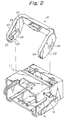
- a torsion coil spring 6 is disposed between the lever 21 and an engaging projection 14 (see Figure 2) in order to bias the lever 21 in a given rotary direction relative to the male connector housing 11.
- the torsion coil spring 6 is a common shape shown in Figure 14 and has a ring portion 6a formed by winding a spring wire into a coil and a pair of first and second end portions 6b and 6c extending tangentially from the ring portion 6a.
- the legs 6b and 6c extend straightly by an angle of 180° therebetween as shown in Figure 14 when no external force is applied to the spring 6.
- the arm 22 of the lever 21 is provided in its inner face with a ring slot 25 around the bearing hole 23 for accommodating the ring portion 6a and a pair of first and second holding slots 26 and 27 communicated with the ring slot 25 for accommodating the portions 6b and 6c, as shown in Figure 3.
- An angular distance between the holding slots 26 and 27 is set to be, for example, 60° or so.
- the portions 6b and 6c are received in the holding slots 26 and 27 by approaching the portions 6b and 6c with each other against the elastic force of the torsion coil spring 6.
- An aperture 28 is formed in a middle portion of the (second) holding slots 27 in the arm 22 of the lever 21. The aperture 28 permits a tool pin not shown to eject the second end portion 6c from the second holding slot 27 by inserting the tool pin into the aperture.
- the arm 22 is provided near an outer edge of the first holding slot 27 having the aperture 28 in the inner face with a raised guide 29.
- the raised guide as shown in Figures 5A to 5C, has a ramp face 30 which continuously increases a height with approaching to the second holding slot 27, a flat top 31 and precipice 33 contiguous to the outer edge of the second holding slot 27.
- the torsion coil spring 6 is mounted on the lever 21.
- the first end portion 6b of the spring 6 is received in the first holding slot 26 and the central ring portion 6a is received in the ring slot 25.
- the spring 6 is free of load, so that an angle between the end portions 6b and 6c is about 180°. Accordingly, the second end portion 6c is spaced from the second holding slot 27, as shown in Figure 5A. Then, an elongated tool pin T engages with the second end portion 6c and pushes it against its elastic force to slide it on the inner face of the lever 21 toward the second holding slot 27 in a direction shown by an arrow in Figure 5A.
- the second end portion 6c of the torsion coil spring 6 is naturally accommodated in the second holding slot 27 only by pushing the portion 6c toward the slot 27 by the tool pin T. Accordingly, it is possible to readily accommodate the portion 6c in the slot 27 without pushing it into the slot 27 in the conventional assembly.
- the lever 21 After the torsion coil spring 6 is mounted on the lever 21, the support axles 12 of the male connector housing 11 are fitted in the bearing holes 23 in the lever 21, so that the lever 21 is mounted on the connector housing 11. At this time, since the lever 21 can be mounted on the connector housing 11 in spite of existence of the spring 6, such mounting operation can be simplified.
- the tool pin When the tool pin is inserted into the aperture 28 in the lever 21 to push the second end portion 6c of the spring 6, the second end portion 6c is ejected from the second holding slot 27 and engages with the engaging projection 14 on the male connector housing 11. Consequently, since the first end portion 6b of the spring 6 is still received in the first holding slot 26 while the second end portion 6c engages with the projections in the male connector housing 11, the lever 21 is biased toward the given rotary direction by the elastic force of the spring 6.
- the lever 21 on which the torsion coil spring 6 is mounted beforehand can be mounted on the connector housing 11, the mounting operation of the lever can be greatly simplified and, in addition, the torsion coil spring 6 can be readily attached to the lever 21 by displacing the second end portion 6c in a direction by means of the tool pin.
- the constructing operation of the connector assembly can be considerably improved.
- a side plate or arm 22 of the lever 21 is provided in its inner face with a tool slot 32 extending from an end face across the cam groove 3a to the second holding slot 27.
- the tool slot 32 is formed into a circular arc and has the same depth as that of the cam groove 3a.
- the tool pin T is inserted into the tool slot 32 so that it can push the second end portion 6c toward the second holding slot 27.
- the tool pin T is moved in the tool slot 32 across the cam groove 3a (see Figure 8B) to a position near the second holding slot 27 while displacing the second end portion 6c against its elastic force to a position immediately above the second holding slot 27. Finally, the tool pin T is inclined to the second holding slot 27 to push the second end portion 6c into the second holding slot 27.
- the portion 6c tends to leap over the tool pin T at a position, at which an elastic force of the spring 6 is very enhanced, near the second holding slot 27.
- the tool slot 32 may be provided on only an area between the cam groove 3a and the second holding slot 27, the tool pin T may slide on the inner face of the arm 22 at the beginning of pushing the second end portion 6c, the tool pin will fall down into the cam groove 3a and move in the tool slot 32 communicated with the second holding slot 27 to push the portion 6c into the slot 27. This can prevent the second end portion 6c from leaping over the tool pin T.
Applications Claiming Priority (5)
| Application Number | Priority Date | Filing Date | Title |
|---|---|---|---|
| JP169628/93 | 1993-06-15 | ||
| JP5169628A JP2762897B2 (ja) | 1993-06-15 | 1993-06-15 | レバー式コネクタ |
| JP17998693A JP2734938B2 (ja) | 1993-06-24 | 1993-06-24 | レバー式コネクタ |
| JP179986/93 | 1993-06-24 | ||
| EP94304306A EP0630076B1 (fr) | 1993-06-15 | 1994-06-14 | Construction de connecteur ayant des leviers |
Related Parent Applications (1)
| Application Number | Title | Priority Date | Filing Date |
|---|---|---|---|
| EP94304306.7 Division | 1994-06-14 |
Publications (3)
| Publication Number | Publication Date |
|---|---|
| EP0725461A2 true EP0725461A2 (fr) | 1996-08-07 |
| EP0725461A3 EP0725461A3 (fr) | 1996-09-18 |
| EP0725461B1 EP0725461B1 (fr) | 1997-12-29 |
Family
ID=26492888
Family Applications (2)
| Application Number | Title | Priority Date | Filing Date |
|---|---|---|---|
| EP94304306A Expired - Lifetime EP0630076B1 (fr) | 1993-06-15 | 1994-06-14 | Construction de connecteur ayant des leviers |
| EP96104666A Expired - Lifetime EP0725461B1 (fr) | 1993-06-15 | 1994-06-14 | Construction de connecteur ayant des leviers |
Family Applications Before (1)
| Application Number | Title | Priority Date | Filing Date |
|---|---|---|---|
| EP94304306A Expired - Lifetime EP0630076B1 (fr) | 1993-06-15 | 1994-06-14 | Construction de connecteur ayant des leviers |
Country Status (3)
| Country | Link |
|---|---|
| US (1) | US5476391A (fr) |
| EP (2) | EP0630076B1 (fr) |
| DE (2) | DE69407614T2 (fr) |
Cited By (2)
| Publication number | Priority date | Publication date | Assignee | Title |
|---|---|---|---|---|
| EP0961361A2 (fr) * | 1998-05-29 | 1999-12-01 | Molex Incorporated | Connecteur à levier de verrouillage |
| DE10222088B4 (de) * | 2001-05-29 | 2015-01-15 | Sumitomo Wiring Systems, Ltd. | Hebeltyp-Verbinder |
Families Citing this family (13)
| Publication number | Priority date | Publication date | Assignee | Title |
|---|---|---|---|---|
| JP2815090B2 (ja) * | 1994-09-06 | 1998-10-27 | 矢崎総業株式会社 | コネクタの操作レバー装着方法及び操作レバー装着機構 |
| JP3075164B2 (ja) * | 1996-01-16 | 2000-08-07 | 住友電装株式会社 | レバー式コネクタ |
| JP3206431B2 (ja) * | 1996-06-05 | 2001-09-10 | 住友電装株式会社 | 樹脂成形品のロック装置 |
| US6428353B2 (en) * | 2000-07-03 | 2002-08-06 | Yazaki Corporation | Connector support mechanism for interconnecting connectors |
| US6406309B1 (en) * | 2000-09-29 | 2002-06-18 | International Business Machines Corporation | Enhanced arrangement for disengaging and separating two mated components |
| US6975491B2 (en) * | 2002-10-11 | 2005-12-13 | Silverman Arthur A | Electrical ground protection device and method |
| DE102006024963B4 (de) * | 2005-05-30 | 2013-04-18 | Yazaki Corp. | Verbinder vom Hebeltyp |
| JP4867875B2 (ja) * | 2007-09-18 | 2012-02-01 | 日立電線株式会社 | レバー式コネクタ |
| US8784127B2 (en) * | 2012-06-11 | 2014-07-22 | Delphi Technologies, Inc. | Electrical connection system including mating assist lever that contains locking means and connector position assurance member that interacts therewith |
| JP2016009597A (ja) * | 2014-06-24 | 2016-01-18 | 日本航空電子工業株式会社 | コネクタ |
| EP3012922B8 (fr) * | 2014-10-20 | 2017-11-01 | Stäubli Electrical Connectors AG | Système de fermeture à levier pivotant pour système de boîtier |
| JP6621378B2 (ja) * | 2016-06-07 | 2019-12-18 | タイコエレクトロニクスジャパン合同会社 | コネクタおよびコネクタ組立体 |
| KR102234243B1 (ko) * | 2019-08-19 | 2021-04-02 | 앱티브 테크놀러지스 리미티드 | 커넥터 및 이를 포함하는 커넥터 조립체 |
Citations (4)
| Publication number | Priority date | Publication date | Assignee | Title |
|---|---|---|---|---|
| DE1151580B (de) * | 1960-10-17 | 1963-07-18 | Harting Elektro W | Mehrpolige elektrische Steckvorrichtung mit U-foermigem Verschlussbuegel |
| US4516819A (en) * | 1982-08-09 | 1985-05-14 | Societe D'exploitation Des Procedes Marechal | Make and break electrical connector |
| US5135408A (en) * | 1990-10-31 | 1992-08-04 | Yazaki Corporation | Connector assembly |
| US5178553A (en) * | 1991-03-15 | 1993-01-12 | Yazaki Corporation | Lever-operated connector assembly |
Family Cites Families (4)
| Publication number | Priority date | Publication date | Assignee | Title |
|---|---|---|---|---|
| JPH0134307Y2 (fr) * | 1985-02-26 | 1989-10-18 | ||
| DE3527916A1 (de) * | 1985-08-03 | 1987-02-12 | Cannon Electric Gmbh | Elektrische steckerkupplung |
| US5174785A (en) * | 1990-07-17 | 1992-12-29 | Yazaki Corporation | Low insertion-withdrawal force electric connector |
| JP2531000Y2 (ja) * | 1991-10-14 | 1997-04-02 | 住友電装株式会社 | コネクタ |
-
1994
- 1994-06-08 US US08/255,374 patent/US5476391A/en not_active Expired - Lifetime
- 1994-06-14 DE DE69407614T patent/DE69407614T2/de not_active Expired - Lifetime
- 1994-06-14 EP EP94304306A patent/EP0630076B1/fr not_active Expired - Lifetime
- 1994-06-14 DE DE69402616T patent/DE69402616T2/de not_active Expired - Lifetime
- 1994-06-14 EP EP96104666A patent/EP0725461B1/fr not_active Expired - Lifetime
Patent Citations (4)
| Publication number | Priority date | Publication date | Assignee | Title |
|---|---|---|---|---|
| DE1151580B (de) * | 1960-10-17 | 1963-07-18 | Harting Elektro W | Mehrpolige elektrische Steckvorrichtung mit U-foermigem Verschlussbuegel |
| US4516819A (en) * | 1982-08-09 | 1985-05-14 | Societe D'exploitation Des Procedes Marechal | Make and break electrical connector |
| US5135408A (en) * | 1990-10-31 | 1992-08-04 | Yazaki Corporation | Connector assembly |
| US5178553A (en) * | 1991-03-15 | 1993-01-12 | Yazaki Corporation | Lever-operated connector assembly |
Cited By (3)
| Publication number | Priority date | Publication date | Assignee | Title |
|---|---|---|---|---|
| EP0961361A2 (fr) * | 1998-05-29 | 1999-12-01 | Molex Incorporated | Connecteur à levier de verrouillage |
| EP0961361A3 (fr) * | 1998-05-29 | 2001-02-07 | Molex Incorporated | Connecteur à levier de verrouillage |
| DE10222088B4 (de) * | 2001-05-29 | 2015-01-15 | Sumitomo Wiring Systems, Ltd. | Hebeltyp-Verbinder |
Also Published As
| Publication number | Publication date |
|---|---|
| EP0725461A3 (fr) | 1996-09-18 |
| DE69402616T2 (de) | 1997-08-14 |
| DE69407614T2 (de) | 1998-05-07 |
| EP0725461B1 (fr) | 1997-12-29 |
| DE69407614D1 (de) | 1998-02-05 |
| EP0630076A1 (fr) | 1994-12-21 |
| US5476391A (en) | 1995-12-19 |
| EP0630076B1 (fr) | 1997-04-16 |
| DE69402616D1 (de) | 1997-05-22 |
Similar Documents
| Publication | Publication Date | Title |
|---|---|---|
| EP0630076B1 (fr) | Construction de connecteur ayant des leviers | |
| US5151040A (en) | Electrical connector for repeated connection to integrated circuit grid array devices | |
| US5226842A (en) | Female terminal | |
| EP0727847B1 (fr) | Connecteur actionné par levier | |
| US5562465A (en) | Lever-type connector | |
| US5823813A (en) | Connector position assurance device | |
| EP1324260B1 (fr) | Mécanisme d'éjection pour un connecteur de carte | |
| US6120308A (en) | Electrical connector assembly which can be rotatably connected and disconnected | |
| EP0895178B1 (fr) | Connecteur de carte | |
| EP0769829B1 (fr) | Connecteur électrique pour carte de PC | |
| US10340618B1 (en) | Electrical terminal housing with releasable terminal locks | |
| EP0618646B1 (fr) | Connecteur actionné par levier | |
| US5083936A (en) | Terminal assembly | |
| US5478263A (en) | Terminal for connector with engaging mechanism | |
| EP0954061B1 (fr) | Un connecteur | |
| US7086882B2 (en) | Card connector having a retarding mechanism for retarding an ejecting operation of a card | |
| US5181857A (en) | Latch mechanism for a header | |
| EP0632544B1 (fr) | Connecteur de bord pour circuit imprimé | |
| EP0630075B1 (fr) | Connecteur à levier d'actionnement et sa méthode d'assemblage et de connexion | |
| US6276948B1 (en) | Connector supporting mechanism | |
| EP1507318B1 (fr) | Connecteur de carte permettant de retirer facilement la carte après l'éjection | |
| US6186827B1 (en) | Connector supporting mechanism | |
| EP1024560B1 (fr) | Connecteur électrique en deux parties | |
| US6159026A (en) | Electrical card connector | |
| US6648687B2 (en) | Method for mounting a connector on a printed circuit board, and shielded connector and lower shielding plate for use in such a method |
Legal Events
| Date | Code | Title | Description |
|---|---|---|---|
| PUAI | Public reference made under article 153(3) epc to a published international application that has entered the european phase |
Free format text: ORIGINAL CODE: 0009012 |
|
| PUAL | Search report despatched |
Free format text: ORIGINAL CODE: 0009013 |
|
| 17P | Request for examination filed |
Effective date: 19960324 |
|
| AC | Divisional application: reference to earlier application |
Ref document number: 630076 Country of ref document: EP |
|
| AK | Designated contracting states |
Kind code of ref document: A2 Designated state(s): DE GB |
|
| AK | Designated contracting states |
Kind code of ref document: A3 Designated state(s): DE GB |
|
| GRAG | Despatch of communication of intention to grant |
Free format text: ORIGINAL CODE: EPIDOS AGRA |
|
| 17Q | First examination report despatched |
Effective date: 19970307 |
|
| GRAG | Despatch of communication of intention to grant |
Free format text: ORIGINAL CODE: EPIDOS AGRA |
|
| GRAH | Despatch of communication of intention to grant a patent |
Free format text: ORIGINAL CODE: EPIDOS IGRA |
|
| GRAH | Despatch of communication of intention to grant a patent |
Free format text: ORIGINAL CODE: EPIDOS IGRA |
|
| GRAA | (expected) grant |
Free format text: ORIGINAL CODE: 0009210 |
|
| AC | Divisional application: reference to earlier application |
Ref document number: 630076 Country of ref document: EP |
|
| AK | Designated contracting states |
Kind code of ref document: B1 Designated state(s): DE GB |
|
| REF | Corresponds to: |
Ref document number: 69407614 Country of ref document: DE Date of ref document: 19980205 |
|
| PLBE | No opposition filed within time limit |
Free format text: ORIGINAL CODE: 0009261 |
|
| STAA | Information on the status of an ep patent application or granted ep patent |
Free format text: STATUS: NO OPPOSITION FILED WITHIN TIME LIMIT |
|
| 26N | No opposition filed | ||
| REG | Reference to a national code |
Ref country code: GB Ref legal event code: IF02 |
|
| PGFP | Annual fee paid to national office [announced via postgrant information from national office to epo] |
Ref country code: DE Payment date: 20130612 Year of fee payment: 20 Ref country code: GB Payment date: 20130612 Year of fee payment: 20 |
|
| REG | Reference to a national code |
Ref country code: DE Ref legal event code: R071 Ref document number: 69407614 Country of ref document: DE |
|
| REG | Reference to a national code |
Ref country code: GB Ref legal event code: PE20 Expiry date: 20140613 |
|
| PG25 | Lapsed in a contracting state [announced via postgrant information from national office to epo] |
Ref country code: GB Free format text: LAPSE BECAUSE OF EXPIRATION OF PROTECTION Effective date: 20140613 |
|
| PG25 | Lapsed in a contracting state [announced via postgrant information from national office to epo] |
Ref country code: DE Free format text: LAPSE BECAUSE OF EXPIRATION OF PROTECTION Effective date: 20140617 |