EP0723928A1 - Procédé et dispositif pour la manipulation de récipients - Google Patents
Procédé et dispositif pour la manipulation de récipients Download PDFInfo
- Publication number
- EP0723928A1 EP0723928A1 EP96100235A EP96100235A EP0723928A1 EP 0723928 A1 EP0723928 A1 EP 0723928A1 EP 96100235 A EP96100235 A EP 96100235A EP 96100235 A EP96100235 A EP 96100235A EP 0723928 A1 EP0723928 A1 EP 0723928A1
- Authority
- EP
- European Patent Office
- Prior art keywords
- closure
- mouth
- vessel
- holding element
- closing tool
- Prior art date
- Legal status (The legal status is an assumption and is not a legal conclusion. Google has not performed a legal analysis and makes no representation as to the accuracy of the status listed.)
- Granted
Links
- 238000000034 method Methods 0.000 title claims description 18
- 239000012530 fluid Substances 0.000 claims abstract description 11
- 239000007789 gas Substances 0.000 claims description 19
- IJGRMHOSHXDMSA-UHFFFAOYSA-N Atomic nitrogen Chemical compound N#N IJGRMHOSHXDMSA-UHFFFAOYSA-N 0.000 claims description 12
- 238000002347 injection Methods 0.000 claims description 12
- 239000007924 injection Substances 0.000 claims description 12
- 239000007788 liquid Substances 0.000 claims description 10
- 229910052757 nitrogen Inorganic materials 0.000 claims description 6
- 239000003570 air Substances 0.000 description 13
- 239000007799 cork Substances 0.000 description 10
- 238000006073 displacement reaction Methods 0.000 description 6
- 238000007789 sealing Methods 0.000 description 6
- 239000006260 foam Substances 0.000 description 5
- 235000013405 beer Nutrition 0.000 description 3
- 235000013361 beverage Nutrition 0.000 description 3
- 239000000945 filler Substances 0.000 description 3
- XLYOFNOQVPJJNP-UHFFFAOYSA-N water Substances O XLYOFNOQVPJJNP-UHFFFAOYSA-N 0.000 description 3
- 238000007664 blowing Methods 0.000 description 2
- 238000010276 construction Methods 0.000 description 2
- 230000000694 effects Effects 0.000 description 2
- 238000001704 evaporation Methods 0.000 description 2
- 239000011261 inert gas Substances 0.000 description 2
- 239000000243 solution Substances 0.000 description 2
- 239000012080 ambient air Substances 0.000 description 1
- QVGXLLKOCUKJST-UHFFFAOYSA-N atomic oxygen Chemical compound [O] QVGXLLKOCUKJST-UHFFFAOYSA-N 0.000 description 1
- 238000011109 contamination Methods 0.000 description 1
- 230000008020 evaporation Effects 0.000 description 1
- 238000005187 foaming Methods 0.000 description 1
- 230000001771 impaired effect Effects 0.000 description 1
- 208000015181 infectious disease Diseases 0.000 description 1
- 244000005700 microbiome Species 0.000 description 1
- 230000004048 modification Effects 0.000 description 1
- 238000012986 modification Methods 0.000 description 1
- 235000015097 nutrients Nutrition 0.000 description 1
- 239000001301 oxygen Substances 0.000 description 1
- 229910052760 oxygen Inorganic materials 0.000 description 1
- 230000000630 rising effect Effects 0.000 description 1
- 230000008016 vaporization Effects 0.000 description 1
Images


Classifications
-
- B—PERFORMING OPERATIONS; TRANSPORTING
- B67—OPENING, CLOSING OR CLEANING BOTTLES, JARS OR SIMILAR CONTAINERS; LIQUID HANDLING
- B67B—APPLYING CLOSURE MEMBERS TO BOTTLES JARS, OR SIMILAR CONTAINERS; OPENING CLOSED CONTAINERS
- B67B3/00—Closing bottles, jars or similar containers by applying caps
- B67B3/02—Closing bottles, jars or similar containers by applying caps by applying flanged caps, e.g. crown caps, and securing by deformation of flanges
- B67B3/10—Capping heads for securing caps
- B67B3/12—Capping heads for securing caps characterised by being movable axially relative to cap to deform flanges thereof, e.g. to press projecting flange rims inwardly
-
- B—PERFORMING OPERATIONS; TRANSPORTING
- B67—OPENING, CLOSING OR CLEANING BOTTLES, JARS OR SIMILAR CONTAINERS; LIQUID HANDLING
- B67C—CLEANING, FILLING WITH LIQUIDS OR SEMILIQUIDS, OR EMPTYING, OF BOTTLES, JARS, CANS, CASKS, BARRELS, OR SIMILAR CONTAINERS, NOT OTHERWISE PROVIDED FOR; FUNNELS
- B67C3/00—Bottling liquids or semiliquids; Filling jars or cans with liquids or semiliquids using bottling or like apparatus; Filling casks or barrels with liquids or semiliquids
- B67C3/02—Bottling liquids or semiliquids; Filling jars or cans with liquids or semiliquids using bottling or like apparatus
- B67C3/22—Details
- B67C3/222—Head-space air removing devices, e.g. by inducing foam
Definitions
- the invention relates to a method and a device for treating vessels according to the preamble of claim 1 and claim 11, respectively.
- a high-pressure injection device is used to inject a hot water jet into the filled, still open bottles in order to foam the beer in the bottle neck. Due to the foam increase, ideally right up to the bottle mouth, the air should be displaced before the bottles are closed (DE 33 11 200 C1). In addition, an attempt is made immediately before touching down and
- the invention has for its object to bring about an improvement.
- the proposed solution is an effective way of effectively displacing air from the neck or head space of a bottle and especially from the closure before the closure is finally attached to the vessel, without having to provide additional inert gas blowing devices in the area of the closure tools.
- the fact that the closure is brought to the bottle mouth after the injection process, but in contrast to the previous procedure is not immediately pressed sealingly against the mouth and fastened by deformation, but first a sufficiently long period of time close to the mouth of the bottle in an open Mouth shielding position is held, the excited by the injection process in the bottle interior and increased fluid release or release can be used to displace the air from the recess of the closure.
- the proposed solution is particularly effective when a liquid gas, in particular liquid nitrogen, is injected into the bottles after filling.
- a liquid gas in particular liquid nitrogen
- the liquid gas evaporating when entering a filled bottle creates an intense one Gas release in the bottle interior.
- the resulting gas evolution and flow can be so strong with the appropriate dosage that the closure can even be placed directly on the mouth in the shielding position.
- An increase in pressure in the interior of the bottle then raises the closure at a sufficiently high gas pressure so that the aforementioned gas flow between the closure and the mouth is created with the air displacement effect.
- Air displacement by vaporizing liquefied gas brings other advantages compared to the known foaming of the beverage by means of injected hot water or the like, e.g. less contamination of the outside of the bottle and the closing tools due to non-overflowing foam. This considerably reduces the risk of infection from contaminated sealing tools, since the lack of beer foam largely removes the nutrient base from the undesired microorganisms in the gaps of the sealing tools.
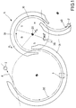
- FIG. 1 shows part of a filler carousel 8, indicated only by a dash-dotted line, and the rotor 10, likewise only indicated schematically, of a capping machine 9, which is connected via a transfer starwheel 30 to the outlet of the filler carousel 8 and is driven synchronously with it.
- a stationary injection device 7 for liquid nitrogen is arranged on the circulation path of the transfer star wheel 30, between filler carousel 8 and the inlet of the sealing machine 9.
- the position of the injection device 7 can be further away from the illustration or closer to the inlet of the sealing machine 9 and / or the injection pressure can be changed.
- the rotor 10 of the capping machine 9 is, in a manner known per se, with receiving pockets (not shown) for the bottles 2, which are arranged in the receiving pockets by guide rails 31 which are arranged in a fixed manner on the orbit be kept equipped.
- an outlet star wheel 40 is arranged at its outlet.
- a closure supply station 39 is positioned on the orbit of the rotor 10 between the outlet star wheel 40 and the transfer star wheel 30.
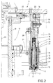
- FIG. 2 shows a vertical section through the capper upper part from its inner axis of rotation 20 to its outer periphery.
- the rotor 10 consists essentially of a revolving drivable center shaft 19 with a support disk 21 rigidly attached to it, which has on its outer circumference bores lying on a pitch circle for receiving the closing tools 11.
- a rotationally fixed support 23 is mounted by means of a rotary bearing 22, to which a control cam 18 is attached.
- a closing tool 11 consists of a guide tube 24, which is inserted through the aforementioned bore in the supporting disk 21 of the rotor 10 and in which a rod 25 carrying an interchangeably fastened closing cone 28, which is attached at its lower end, can be raised and lowered.
- the rod 25 is secured against rotation by means of a guide pin 26 which is fastened to the support disk 21 laterally next to the guide tube 24.
- a pair of cam rollers 14, 15 is attached, one cam roller 14 on the top and the second cam roller 15 on the Underside of the control curve 18 is present.
- a pressure plunger 13 is guided, which has a magnet 12 at its lower end for holding a crown cap 1.
- the plunger 13 is permanently pressed downwards by a comparatively soft coil spring 16.
- a first shoulder surface 27 of the pressure plunger 13 is constantly on the top of the closing cone 28 or the support ring 29 (see Fig. 3).
- a sliding sleeve 32 is slidably mounted on the pressure ram 13.
- a hard helical spring 34 is clamped between this sliding sleeve 32 and a second shoulder surface 33 located at the lower end of the pressure ram 13.
- the plunger 13 is a certain, short distance alone against the low force of the soft coil spring 16 axially displaceable relative to the rod 25 until the top of the sliding sleeve 32 comes to rest on a step 35 formed in the rod 25. With a further displacement of the pressure plunger 13 upwards, the then effective, considerably higher force of the hard spring 34 must also be overcome.
- Fig. 3 the lower end of the closing tool 11 is shown in an enlarged view.
- the lower end of the guide tube 24 with the rod 25 projecting therefrom can be seen.
- a support ring 29 is detachably fastened with screws, which is exchangeable Receiving the annular sealing cone 28 is used.
- the closing cone 28 is partially penetrated by a magnet 12 connected to the pressing plunger 13 by pinning, the end face of the magnet 12 being set back inwards with respect to the lower edge of the closing cone. A centering of the crown cap 1 held by the magnet 12 in the sealing cone 28 is thereby achieved.
- the position II of the closing tool 11 is shown, in which the crown cap 1 covers or shields the mouth 3 of the bottle 2, which has not yet been finally closed. 3 that the top of the mouth 3 is only a few millimeters apart from the inner end face 36 of the crown cap 1 in this position. The distance can vary due to the height tolerances of the bottles 2 standing on a stand plate (not shown).
- the lower edge 6 of the crown cork 1 lies below the mouth 3, with an annular gap 4 between the edge of the cork 1 projecting vertically downward from the end face 36 and the circumferential surface of the mouth.
- the closing tool 11 is further lowered by the control cam 18, whereby the crown cap 1 is pressed gas-tight against the mouth 3 and subsequently the edge 6 of the crown cap 1 is deformed radially inward by a further downward movement of the closing cone 28 against the force of the hard spring 34 and the mouth of the bottle 2 is covered (position III).
- the three relevant height positions I, II, III of a closing tool 11, depending on its rotational position during a revolution with the rotor 10 of the closing machine 9, can be seen from the development of the curve shape of the control curve 18 shown in FIG. 4.
- the initial position of a closing tool 11, denoted by zero degrees, is located at the closing feed station 39 (see FIG. 1).
- the top position is that
- the ready position of the closing tool 11 denotes, in which a magnet 1 is supplied with a cork 1 through the closing feed station 39 and then a bottle 2 is inserted concentrically under the closing tool 11 through the transfer star wheel 30.
- the cork in the manner described above is gassed on its inside by gas emerging from bottle 2 (phase B).
- the closing tool 11 is then further lowered until the lowest position III, the closing position (position V), and then returned to the ready position I (phase H) to release and remove the now closed bottle (phase H), in order to have a cork again 1 at the shutter feed station 39.
Applications Claiming Priority (2)
| Application Number | Priority Date | Filing Date | Title |
|---|---|---|---|
| DE19502452 | 1995-01-26 | ||
| DE19502452A DE19502452A1 (de) | 1995-01-26 | 1995-01-26 | Verfahren und Vorrichtung zum Behandeln von Gefäßen |
Publications (2)
| Publication Number | Publication Date |
|---|---|
| EP0723928A1 true EP0723928A1 (fr) | 1996-07-31 |
| EP0723928B1 EP0723928B1 (fr) | 1997-06-18 |
Family
ID=7752400
Family Applications (1)
| Application Number | Title | Priority Date | Filing Date |
|---|---|---|---|
| EP96100235A Expired - Lifetime EP0723928B1 (fr) | 1995-01-26 | 1996-01-10 | Procédé et dispositif pour la manipulation de récipients |
Country Status (4)
| Country | Link |
|---|---|
| US (1) | US5802812A (fr) |
| EP (1) | EP0723928B1 (fr) |
| JP (1) | JPH08244885A (fr) |
| DE (2) | DE19502452A1 (fr) |
Cited By (5)
| Publication number | Priority date | Publication date | Assignee | Title |
|---|---|---|---|---|
| EP0827936A1 (fr) * | 1996-08-29 | 1998-03-11 | Air Products And Chemicals, Inc. | Méthode et dispositif pour l'élimination de l'air du col de bouteilles remplies avec une boisson carbonatée |
| EP0841300A1 (fr) * | 1996-10-10 | 1998-05-13 | Olaf Dipl.-Ing. Babel | Méthode et dispositif pour faire mousser le liquide du goulot des bouteilles remplies avec des boissons gazeuses |
| FR2756085A1 (fr) * | 1996-11-21 | 1998-05-22 | Air Liquide | Installation de traitement de produits alimentaires commandee en fonction de parametres de consigne |
| EP0875484A1 (fr) * | 1997-05-01 | 1998-11-04 | Linde Aktiengesellschaft | Procédé et dispositif pour chasser l'air de l'espace au-dessus du liquide remplissant des récipients |
| ITMI20121543A1 (it) * | 2012-09-18 | 2014-03-19 | Franco Comoli | Dispositivo di tappatura o stappatura |
Families Citing this family (12)
| Publication number | Priority date | Publication date | Assignee | Title |
|---|---|---|---|---|
| AU3344199A (en) * | 1998-04-17 | 1999-11-08 | Toyo Seikan Kaisha Ltd. | Method and device for manufacturing positive pressure packaging body |
| US7040075B2 (en) | 2001-08-08 | 2006-05-09 | The Clorox Company | Nitrogen cap chute end |
| EP1550631B1 (fr) * | 2002-05-23 | 2007-06-20 | Yoshida, Eiji | Dispositif de remplacement de bouchon et procede de remplacement de bouchon |
| ITTO20030229A1 (it) * | 2003-03-27 | 2004-09-28 | Arol Spa | Testa capsulatrice per l'applicazione sotto vuoto di capsule |
| US7219480B2 (en) * | 2003-08-06 | 2007-05-22 | Alcoa Closure Systems International, Inc. | Capping and nitrogen dosing apparatus |
| DE102007016159B4 (de) * | 2007-04-02 | 2018-11-22 | Khs Corpoplast Gmbh | Verfahren und Vorrichtung zum sterilen Abfüllen |
| US7614202B2 (en) * | 2007-11-27 | 2009-11-10 | Atlas Vac Machine Co., Llc | Sealer and interchangeable tooling therefor |
| US20090188613A1 (en) * | 2008-01-28 | 2009-07-30 | Spear Usa, Llc | Method and apparatus for applying pressure sensitive adhesive labels to containers |
| TWI472459B (zh) * | 2008-05-19 | 2015-02-11 | Melrose David | 移除真空壓力之頂部空間改性方法及其裝置 |
| DE102008032822A1 (de) | 2008-07-11 | 2010-01-14 | Krones Ag | Vorrichtung zum Abfüllen von Getränken |
| DE102009003025A1 (de) * | 2009-05-12 | 2010-11-18 | Ball Packaging Europe Gmbh | Verfahren zum Befüllen von Lebenmittelbehältern |
| DE102014104323A1 (de) * | 2014-03-27 | 2015-10-01 | Khs Gmbh | Kronkorkenverschluss, Verschlussverfahren und Verschlussvorrichtung für Behälter |
Citations (3)
| Publication number | Priority date | Publication date | Assignee | Title |
|---|---|---|---|---|
| US4099361A (en) * | 1972-03-20 | 1978-07-11 | Crown Cork & Seal Company, Inc. | Apparatus for and method of closing containers |
| DE3226172A1 (de) * | 1982-07-13 | 1984-01-26 | Mitsubishi Jukogyo K.K., Tokyo | Verfahren und vorrichtung zum austausch von luft innerhalb eines behaelterhalses |
| DE3311200C1 (de) * | 1983-03-26 | 1984-04-05 | Krones Ag Hermann Kronseder Maschinenfabrik, 8402 Neutraubling | Vorrichtung zum Behandeln von Flaschen od.dgl. |
Family Cites Families (21)
| Publication number | Priority date | Publication date | Assignee | Title |
|---|---|---|---|---|
| US2127964A (en) * | 1935-01-03 | 1938-08-23 | Ryan Coffee Corp | Capping and sealing apparatus |
| US2131876A (en) * | 1936-07-22 | 1938-10-04 | Lever Brothers Ltd | Apparatus for blanketing comestibles with inert gas |
| US2630957A (en) * | 1950-03-29 | 1953-03-10 | Owens Illinois Glass Co | Method and apparatus for sealing containers |
| US3246447A (en) * | 1963-02-25 | 1966-04-19 | Anchor Hocking Glass Corp | Air purging mechanism |
| US3443352A (en) * | 1967-04-14 | 1969-05-13 | Int Machinery Corp | Packaging machine and method |
| EP0092966B1 (fr) * | 1982-04-22 | 1987-01-28 | Daiwa Can Company, Limited | Procédé de fabrication d'un récipient fermé contenant un comestible et un gaz |
| GB2125937B (en) * | 1982-08-26 | 1986-06-25 | Metal Box Plc | Dispensing volatile liquids |
| FR2533015A1 (fr) * | 1982-09-13 | 1984-03-16 | Air Liquide | Procede et dispositif d'injection d'un gaz liquefie de pressurisation dans des recipients |
| US4583346A (en) * | 1983-07-19 | 1986-04-22 | National Can Corporation | Method and apparatus for pressurizing containers |
| US4662154A (en) * | 1984-10-12 | 1987-05-05 | Continental Can Company, Inc. | Liquid inert gas dispenser and control |
| DE3515334A1 (de) * | 1985-04-27 | 1986-10-30 | Krones Ag Hermann Kronseder Maschinenfabrik, 8402 Neutraubling | Gefaessverschliessmaschine |
| FR2581027B1 (fr) * | 1985-04-29 | 1987-11-20 | Air Liquide | Procede d'inertage d'emballages etanches et installation de mise en oeuvre |
| JPS63191723A (ja) * | 1987-01-31 | 1988-08-09 | 北海製罐株式会社 | 缶詰に不活性ガスを封入する方法およびその装置 |
| FR2613321B1 (fr) * | 1987-03-30 | 1989-10-20 | Air Liquide | Installation d'inertage d'emballages etanches pour produits alimentaires |
| US4880041A (en) * | 1987-04-15 | 1989-11-14 | Tokyo Seikan Kaisha, Ltd. | Apparatus for flowing and filling liquified inert gas |
| FR2619550B1 (fr) * | 1987-08-17 | 1990-02-16 | Air Liquide | Installation de conditionnement de produits dans des recipients |
| US5048954A (en) * | 1989-07-07 | 1991-09-17 | Miradco | Laser-based wheel alignment system |
| US5033254A (en) * | 1990-04-19 | 1991-07-23 | American National Can Company | Head-space calibrated liquified gas dispensing system |
| CA2084783A1 (fr) * | 1990-06-06 | 1991-12-07 | Hermann Kronseder | Methode utilisee pour remplir des contenants et les rendre hermetiques, et dispositif connexe |
| US5251424A (en) * | 1991-01-11 | 1993-10-12 | American National Can Company | Method of packaging products in plastic containers |
| US5457939A (en) * | 1993-09-01 | 1995-10-17 | Optimal Food Processing Research, Inc. | Process for vacuum-packaging foodstuffs in rigid containers |
-
1995
- 1995-01-26 DE DE19502452A patent/DE19502452A1/de not_active Ceased
-
1996
- 1996-01-10 DE DE59600005T patent/DE59600005D1/de not_active Expired - Lifetime
- 1996-01-10 EP EP96100235A patent/EP0723928B1/fr not_active Expired - Lifetime
- 1996-01-22 US US08/589,714 patent/US5802812A/en not_active Expired - Lifetime
- 1996-01-26 JP JP8011730A patent/JPH08244885A/ja active Pending
Patent Citations (3)
| Publication number | Priority date | Publication date | Assignee | Title |
|---|---|---|---|---|
| US4099361A (en) * | 1972-03-20 | 1978-07-11 | Crown Cork & Seal Company, Inc. | Apparatus for and method of closing containers |
| DE3226172A1 (de) * | 1982-07-13 | 1984-01-26 | Mitsubishi Jukogyo K.K., Tokyo | Verfahren und vorrichtung zum austausch von luft innerhalb eines behaelterhalses |
| DE3311200C1 (de) * | 1983-03-26 | 1984-04-05 | Krones Ag Hermann Kronseder Maschinenfabrik, 8402 Neutraubling | Vorrichtung zum Behandeln von Flaschen od.dgl. |
Cited By (7)
| Publication number | Priority date | Publication date | Assignee | Title |
|---|---|---|---|---|
| EP0827936A1 (fr) * | 1996-08-29 | 1998-03-11 | Air Products And Chemicals, Inc. | Méthode et dispositif pour l'élimination de l'air du col de bouteilles remplies avec une boisson carbonatée |
| EP0841300A1 (fr) * | 1996-10-10 | 1998-05-13 | Olaf Dipl.-Ing. Babel | Méthode et dispositif pour faire mousser le liquide du goulot des bouteilles remplies avec des boissons gazeuses |
| FR2756085A1 (fr) * | 1996-11-21 | 1998-05-22 | Air Liquide | Installation de traitement de produits alimentaires commandee en fonction de parametres de consigne |
| EP0849554A1 (fr) * | 1996-11-21 | 1998-06-24 | L'air Liquide, Societe Anonyme Pour L'etude Et L'exploitation Des Procedes Georges Claude | Installation de traitement de produits alimentaires commandée en fonction de paramètres de consigne |
| US5946922A (en) * | 1996-11-21 | 1999-09-07 | L'air Liquide, Societe Anonyme Pour L'etude Et L'exploitation Des Procedes Georges Claude | Food processing plant controlled on the basis of set-point parameters |
| EP0875484A1 (fr) * | 1997-05-01 | 1998-11-04 | Linde Aktiengesellschaft | Procédé et dispositif pour chasser l'air de l'espace au-dessus du liquide remplissant des récipients |
| ITMI20121543A1 (it) * | 2012-09-18 | 2014-03-19 | Franco Comoli | Dispositivo di tappatura o stappatura |
Also Published As
| Publication number | Publication date |
|---|---|
| EP0723928B1 (fr) | 1997-06-18 |
| DE59600005D1 (de) | 1997-07-24 |
| JPH08244885A (ja) | 1996-09-24 |
| US5802812A (en) | 1998-09-08 |
| DE19502452A1 (de) | 1996-08-01 |
Similar Documents
| Publication | Publication Date | Title |
|---|---|---|
| EP0723928B1 (fr) | Procédé et dispositif pour la manipulation de récipients | |
| EP2138446B1 (fr) | Système de remplissage à rayon libre | |
| EP0334288B1 (fr) | Procédé pour remplir des récipients avec un produit liquide dans des conditions aseptiques voire stériles ainsi que dispositif pour la mise en oeuvre | |
| DE3515334A1 (de) | Gefaessverschliessmaschine | |
| DE2722254C3 (de) | Flaschenverschließmaschine umlaufender Bauart | |
| EP0414075B1 (fr) | Dispositif de remplissage de récipients | |
| DE2251331B2 (de) | Verfahren zum Abfüllen einer kohlensäurehaltigen Flüssigkeit und Vorrichtung zur Durchführung des Verfahrens | |
| DE3226172C2 (de) | Verfahren und Vorrichtung zum Austausch von Luft innerhalb eines Behälterhalses | |
| DE60208736T2 (de) | Vorrichtung zum Greifen und Handhaben von Flaschen in einer Etikettiermaschine | |
| EP2117986B1 (fr) | Procédé de bouchage de récipients et machine à boucher | |
| DE3640693A1 (de) | Verfahren und vorrichtung zur herstellung von flaschengetraenken | |
| DE3927491A1 (de) | Vorrichtung zum fuellen und verschliessen von behaeltern | |
| EP0531379B1 (fr) | Procede et dispositif de remplissage et de fermeture de recipients | |
| EP0561299A1 (fr) | Procédé et dispositif de fermeture de bouteilles | |
| EP0290649A1 (fr) | Dispositif pour remplir en particulier d'une substance liquide ou solide coulante un récipient, plus particulièrement des fûts, fermés avec un bouchon fileté ou un bouchon de fermeture formé d'une autre façon | |
| DE102006061498A1 (de) | Verfahren zum Verschließen von Behältern sowie Verschließmaschine | |
| EP1632455A1 (fr) | Procédé et dispositif pour remplir des bouteilles et récipients similaires | |
| EP1544157B1 (fr) | Machine de remplissage pour remplir des récipients | |
| WO2018007137A1 (fr) | Procédé de remplissage de récipients | |
| WO2009095054A1 (fr) | Dispositif et procédé destinés à faire mousser des produits soutirés dans des récipients | |
| DE4030081A1 (de) | Aufschaeumvorrichtung zum verdraengen des restluftvolumens aus mit einem aufschaeumbaren fluessigen fuellgut gefuellten behaeltern, insbesondere flaschen | |
| DE4229580A1 (de) | Verfahren und Vorrichtung zur Überkopf-Behandlung von Flaschen | |
| DE4018121C2 (fr) | ||
| WO2015058889A1 (fr) | Dispositif et procédé de traitement d'emballages | |
| EP0692426A1 (fr) | Procédé et dispositif pour la fermeture de récipients |
Legal Events
| Date | Code | Title | Description |
|---|---|---|---|
| PUAI | Public reference made under article 153(3) epc to a published international application that has entered the european phase |
Free format text: ORIGINAL CODE: 0009012 |
|
| 17P | Request for examination filed |
Effective date: 19960110 |
|
| AK | Designated contracting states |
Kind code of ref document: A1 Designated state(s): DE FR GB IT |
|
| GRAG | Despatch of communication of intention to grant |
Free format text: ORIGINAL CODE: EPIDOS AGRA |
|
| GRAH | Despatch of communication of intention to grant a patent |
Free format text: ORIGINAL CODE: EPIDOS IGRA |
|
| GRAH | Despatch of communication of intention to grant a patent |
Free format text: ORIGINAL CODE: EPIDOS IGRA |
|
| GRAA | (expected) grant |
Free format text: ORIGINAL CODE: 0009210 |
|
| AK | Designated contracting states |
Kind code of ref document: B1 Designated state(s): DE FR GB IT |
|
| REF | Corresponds to: |
Ref document number: 59600005 Country of ref document: DE Date of ref document: 19970724 |
|
| ET | Fr: translation filed | ||
| GBT | Gb: translation of ep patent filed (gb section 77(6)(a)/1977) |
Effective date: 19970903 |
|
| PLBE | No opposition filed within time limit |
Free format text: ORIGINAL CODE: 0009261 |
|
| STAA | Information on the status of an ep patent application or granted ep patent |
Free format text: STATUS: NO OPPOSITION FILED WITHIN TIME LIMIT |
|
| 26N | No opposition filed | ||
| REG | Reference to a national code |
Ref country code: GB Ref legal event code: IF02 |
|
| PG25 | Lapsed in a contracting state [announced via postgrant information from national office to epo] |
Ref country code: IT Free format text: LAPSE BECAUSE OF NON-PAYMENT OF DUE FEES Effective date: 20050110 |
|
| PGFP | Annual fee paid to national office [announced via postgrant information from national office to epo] |
Ref country code: GB Payment date: 20060227 Year of fee payment: 11 |
|
| GBPC | Gb: european patent ceased through non-payment of renewal fee |
Effective date: 20070110 |
|
| PG25 | Lapsed in a contracting state [announced via postgrant information from national office to epo] |
Ref country code: GB Free format text: LAPSE BECAUSE OF NON-PAYMENT OF DUE FEES Effective date: 20070110 |
|
| PGRI | Patent reinstated in contracting state [announced from national office to epo] |
Ref country code: IT Effective date: 20091201 |
|
| PGFP | Annual fee paid to national office [announced via postgrant information from national office to epo] |
Ref country code: IT Payment date: 20100115 Year of fee payment: 15 Ref country code: FR Payment date: 20100208 Year of fee payment: 15 |
|
| PGFP | Annual fee paid to national office [announced via postgrant information from national office to epo] |
Ref country code: DE Payment date: 20100107 Year of fee payment: 15 |
|
| REG | Reference to a national code |
Ref country code: FR Ref legal event code: ST Effective date: 20110930 |
|
| PG25 | Lapsed in a contracting state [announced via postgrant information from national office to epo] |
Ref country code: FR Free format text: LAPSE BECAUSE OF NON-PAYMENT OF DUE FEES Effective date: 20110131 |
|
| REG | Reference to a national code |
Ref country code: DE Ref legal event code: R119 Ref document number: 59600005 Country of ref document: DE Effective date: 20110802 |
|
| PG25 | Lapsed in a contracting state [announced via postgrant information from national office to epo] |
Ref country code: IT Free format text: LAPSE BECAUSE OF NON-PAYMENT OF DUE FEES Effective date: 20110110 |
|
| PG25 | Lapsed in a contracting state [announced via postgrant information from national office to epo] |
Ref country code: DE Free format text: LAPSE BECAUSE OF NON-PAYMENT OF DUE FEES Effective date: 20110802 |