EP0723925A2 - Gerät zum stabilen Übergeben von bahnartigem Material - Google Patents
Gerät zum stabilen Übergeben von bahnartigem Material Download PDFInfo
- Publication number
- EP0723925A2 EP0723925A2 EP96101049A EP96101049A EP0723925A2 EP 0723925 A2 EP0723925 A2 EP 0723925A2 EP 96101049 A EP96101049 A EP 96101049A EP 96101049 A EP96101049 A EP 96101049A EP 0723925 A2 EP0723925 A2 EP 0723925A2
- Authority
- EP
- European Patent Office
- Prior art keywords
- belt
- absorbing
- feeding
- chamber
- pressure
- Prior art date
- Legal status (The legal status is an assumption and is not a legal conclusion. Google has not performed a legal analysis and makes no representation as to the accuracy of the status listed.)
- Granted
Links
Images


Classifications
-
- B—PERFORMING OPERATIONS; TRANSPORTING
- B65—CONVEYING; PACKING; STORING; HANDLING THIN OR FILAMENTARY MATERIAL
- B65H—HANDLING THIN OR FILAMENTARY MATERIAL, e.g. SHEETS, WEBS, CABLES
- B65H23/00—Registering, tensioning, smoothing or guiding webs
- B65H23/04—Registering, tensioning, smoothing or guiding webs longitudinally
- B65H23/18—Registering, tensioning, smoothing or guiding webs longitudinally by controlling or regulating the web-advancing mechanism, e.g. mechanism acting on the running web
- B65H23/1806—Registering, tensioning, smoothing or guiding webs longitudinally by controlling or regulating the web-advancing mechanism, e.g. mechanism acting on the running web in reel-to-reel type web winding and unwinding mechanism, e.g. mechanism acting on web-roll spindle
-
- B—PERFORMING OPERATIONS; TRANSPORTING
- B65—CONVEYING; PACKING; STORING; HANDLING THIN OR FILAMENTARY MATERIAL
- B65H—HANDLING THIN OR FILAMENTARY MATERIAL, e.g. SHEETS, WEBS, CABLES
- B65H20/00—Advancing webs
- B65H20/30—Arrangements for accumulating surplus web
- B65H20/32—Arrangements for accumulating surplus web by making loops
-
- B—PERFORMING OPERATIONS; TRANSPORTING
- B65—CONVEYING; PACKING; STORING; HANDLING THIN OR FILAMENTARY MATERIAL
- B65H—HANDLING THIN OR FILAMENTARY MATERIAL, e.g. SHEETS, WEBS, CABLES
- B65H23/00—Registering, tensioning, smoothing or guiding webs
- B65H23/04—Registering, tensioning, smoothing or guiding webs longitudinally
- B65H23/042—Sensing the length of a web loop
-
- B—PERFORMING OPERATIONS; TRANSPORTING
- B65—CONVEYING; PACKING; STORING; HANDLING THIN OR FILAMENTARY MATERIAL
- B65H—HANDLING THIN OR FILAMENTARY MATERIAL, e.g. SHEETS, WEBS, CABLES
- B65H23/00—Registering, tensioning, smoothing or guiding webs
- B65H23/04—Registering, tensioning, smoothing or guiding webs longitudinally
- B65H23/24—Registering, tensioning, smoothing or guiding webs longitudinally by fluid action, e.g. to retard the running web
-
- B—PERFORMING OPERATIONS; TRANSPORTING
- B65—CONVEYING; PACKING; STORING; HANDLING THIN OR FILAMENTARY MATERIAL
- B65H—HANDLING THIN OR FILAMENTARY MATERIAL, e.g. SHEETS, WEBS, CABLES
- B65H2301/00—Handling processes for sheets or webs
- B65H2301/40—Type of handling process
- B65H2301/44—Moving, forwarding, guiding material
- B65H2301/449—Features of movement or transforming movement of handled material
- B65H2301/4491—Features of movement or transforming movement of handled material transforming movement from continuous to intermittent or vice versa
-
- B—PERFORMING OPERATIONS; TRANSPORTING
- B65—CONVEYING; PACKING; STORING; HANDLING THIN OR FILAMENTARY MATERIAL
- B65H—HANDLING THIN OR FILAMENTARY MATERIAL, e.g. SHEETS, WEBS, CABLES
- B65H2406/00—Means using fluid
- B65H2406/30—Suction means
- B65H2406/31—Suction box; Suction chambers
- B65H2406/311—Suction box; Suction chambers for accumulating a loop of handled material
-
- B—PERFORMING OPERATIONS; TRANSPORTING
- B65—CONVEYING; PACKING; STORING; HANDLING THIN OR FILAMENTARY MATERIAL
- B65H—HANDLING THIN OR FILAMENTARY MATERIAL, e.g. SHEETS, WEBS, CABLES
- B65H2408/00—Specific machines
- B65H2408/20—Specific machines for handling web(s)
- B65H2408/21—Accumulators
- B65H2408/215—Accumulators supported by vacuum or blown air
-
- B—PERFORMING OPERATIONS; TRANSPORTING
- B65—CONVEYING; PACKING; STORING; HANDLING THIN OR FILAMENTARY MATERIAL
- B65H—HANDLING THIN OR FILAMENTARY MATERIAL, e.g. SHEETS, WEBS, CABLES
- B65H2515/00—Physical entities not provided for in groups B65H2511/00 or B65H2513/00
- B65H2515/30—Forces; Stresses
- B65H2515/34—Pressure, e.g. fluid pressure
Definitions
- the present invention relates to an apparatus for stably transferring belt-like material, and particularly to an apparatus for stably transferring belt-like material provided to a hole forming apparatus for forming fine holes on the belt-like material such as a chip paper of cigarette.
- the hole forming apparatus comprises a supplying apparatus having a delivery roller for delivering rolled chip paper, a hole forming device for irradiating chip paper, which is delivered from the supplying apparatus to be transferred at predetermined speed, with a laser beam so as to form fine holes, a feed roller for transferring chip paper, which has fine holes formed by the hole forming apparatus, at fixed speed, a winding apparatus having a winding roller for winding transferred chip paper, a transfer passage having a plurality of rollers for continuously transferring the belt-like material from the supplying apparatus to the winding apparatus, a plurality of drive motors for driving each of the rollers, and a controlling apparatus for controlling the entire hole forming apparatus.
- the conventional hole forming apparatus comprises a tension detecting apparatus for detecting tension of chip paper to be transferred in order to stably deliver chip paper and wind the delivered chip paper.
- a tension detecting apparatus for detecting a diameter of roll wound around the winding roller to calculate tension of transferring chip paper.
- the controlling apparatus controls the drive of each motor based on the calculated tension of chip paper. In other words, the rotating speed of delivery roller and that of the winding roller are controlled, so that suitable braking force or driving force is applied to the delivery roller and the winding roller, and tension of belt-like material is controlled to be constantly maintained.
- a tension mechanism is provided as a apparatus for stably delivering or winding chip paper.
- the tension mechanism comprises a tension roller, which is provided between the delivery roller and the feed roller or between the feed roller and the winding roller, and which moves up and down by a spring. The tension mechanism relaxes a load applied to the transferring chip paper when the tension roller moves up and down.
- chip paper In processing the belt-like material such as chip paper, it is regarded to be important to set the apparatus to a normal delivering state immediately chip paper is replaced with new one since waste of chip paper can be avoided and ability of production can be improved. Moreover, since chip paper is extremely thin and easily broken, careful treatment is required.
- the respective rollers are started at high speed instantly, and extremely high tension is applied to chip paper and the feed roller. Due to this, there is possibility that chip paper will be broken.
- the apparatus is instantaneously stopped and brake force is abruptly applied to the transferring paper to be stopped. Due to this, high tension is applied to chip paper, and there is possibility that chip paper will be broken.
- the above-mentioned problems may occurs in not only the apparatus for processing the belt-like material such as chip paper of cigarette but also an apparatus for printing or processing wrapping paper cut to a predetermined size.
- An object of the present invention is to provide an apparatus for stably transferring belt-like material, which can be instantaneously started at high speed and stopped. Also, an object of the present invention is to provide a detector for ensuring a stable transfer of belt-like material.
- an apparatus for stably transferring belt-like material comprising transferring means for transferring belt-like material; absorbing and feeding means, having a reserving chamber for reserving the transferred belt-like material, for applying a pressure difference to first and second spaces of the reserving chamber divided by the transferred belt-like material so as to absorb and feed the belt-like material to the reserving chamber; detecting means for detecting an extending position of the belt-like material moving up or down in the reserving chamber; and controlling means for controlling the transferring means in accordance with an output detected by the detecting means so as to adjust a transferring speed of the belt-like material.
- an apparatus for stably transferring belt-like material comprising supplying means for supplying belt-like material; absorbing and feeding means having a reserving chamber for continuously absorbing and feeding the belt-like material supplied from the supplying means, and a pressure detecting chamber, provided at the back of the reserving chamber through a through hole, and closed to detect its internal pressure; transferring means for pulling out the belt-like material absorbed and fed to the reserving chamber of the absorbing and feeding means so as to be transferred; pressure converting means, connected to the pressure detecting chamber of the absorbing and feeding means, for detecting the internal pressure of the pressure detecting chamber changing in accordance with the amount of absorbing and feeding the belt-like material absorbed and fed to the reserving chamber so as to convert the detected internal pressure to an electrical signal; and controlling means for decreasing the amount of supply of the belt-like material supplied by the supplying means when the amount of absorbing and feeding the belt-like material is large, and for increasing the amount of
- an apparatus for stably transferring belt-like material comprising:supplying means for supplying belt-like material; first absorbing and feeding means having a reserving chamber for continuously absorbing and feeding the belt-like material supplied from the supplying means, and a pressure detecting chamber, provided at the back of the reserving chamber through a through hole, and closed to detect its internal pressure; transferring means for pulling out the belt-like material absorbed and fed to the reserving chamber of the first absorbing and feeding means so as to be transferred; first pressure converting means, connected to the pressure detecting chamber of the first absorbing and feeding means, for detecting the internal pressure of the pressure detecting chamber changing in accordance with the amount of absorbing and feeding belt-like material absorbed and fed to the reserving chamber so as to convert the detected internal pressure to an electrical signal; supply controlling means for controlling the amount of supply of the belt-like material supplied by supplying means based on the electrical signal converted by the first pressure converting means; second absorbing and feeding
- an apparatus for detecting an amount of absorbed and fed belt-like material comprising first case means, having an opening portion, for defining a reserving chamber; belt-like material, transferred to the reserving chamber through the opening portion, for dividing the reserving chamber to first and second spaces; second case means, communicated with the reserving chamber through a fine communicating hole, for defining a pressure detecting chamber; absorbing and feeding means for applying negative pressure to the second space of the reserving chamber so as to absorb and feed the belt-like material; and detecting means for detecting pressure of the pressure detecting chamber changing in accordance with an amount of absorbing and feeding the belt-like material.
- the operation of the apparatus can be instantaneously started or stopped at high speed without applying high load to the feed roller regardless of the size of the roll diameter of the belt-like material.
- control is performed based on the internal pressure of the pressure detecting chamber changing in accordance with the amount of absorbing and feeding the belt-like material to the reserving chamber of the absorbing and feeding means, that is, the length, which is from the upper end portion of the reserving chamber to the lowermost end position of the absorbed and fed belt-like material.
- the operation of the apparatus can be instantaneously started or stopped at high speed without applying high load to the belt-like material, the breakage of the belt-like material can be prevented. Due to this, the apparatus can be prevented from being undesirably stopped by the breakage of the belt-like material, thereby the ability of processing the belt-like material can be improved.
- the belt-like material is transferred to the reserving chamber through the opening portion of the reserving chamber so as to divide the reserving chamber to first and second spaces.
- a pressure difference between the first and second spaces of the reserving chamber is generated.
- the internal pressure of the pressure detecting chamber which communicates with the reserving chamber through the fine communicating hole, is changed in accordance with the amount of absorbing and feeding the belt-like material. Therefore, the pressure change of the pressure detecting chamber is detected, thereby the amount of absorbing and feeding the belt-like material can be correctly detected.
- an apparatus for stably transferring belt-like material of the present invention which is provided in, for example, a hole forming apparatus for forming fine holes in the belt-like material such as chip paper of cigarette.
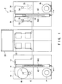
- FIG. 1 is a front view schematically showing a hole forming apparatus having an apparatus for stably transferring belt-like material.
- a punching apparatus 2 comprises a supplying apparatus 10 for delivering belt-like material, e.g., chip paper 16 wound in a roll form, a hole forming apparatus 20 for forming fine holes in chip paper delivered from the supplying apparatus; and a winding apparatus 30 for winding chip paper 1 in which holes are formed by the hole forming device 20.
- the winding apparatus 30 comprises a feed roller 31 to be described later.
- the feed roller 31 draws chip paper 1 from the supplying apparatus 10 to be transferred to the winding apparatus 30 through the hole forming device 20.
- a transferring passage which is formed of a plurality of rollers, to transfer chip paper.
- the supplying apparatus 10 comprises a delivery roller 11 to which the rolled chip paper 16 is attached, a servo motor 12 for driving the delivery roller at a predetermined rotating speed, a brake device 13 for adjusting tension of chip paper 1 delivered from the rolled chip paper 16 attached on the delivery roller 11, a blower 14 for absorbing the delivered chip paper 1, an absorbing and feeding apparatus 40 for continuously absorbing and feeding chip paper 1 when the blower 14 absorbs chip paper 1, and a transferring passage 15 formed of a plurality of rollers.
- Chip paper 1 is mainly pulled out from the rolled chip paper 16 by a feed roller 31 provided in the winding apparatus 30.
- the servo motor 12 for driving the delivery roller 11 is controlled in accordance with an amount of reserved chip paper 1 of the absorbing and feeding apparatus 40 on the supplying apparatus 10.
- the apparatus for stably transferring belt-like material on the supplying apparatus 10 comprises the feed roller 31 functioning as a main roller, the delivery roller 11 functioning as a follow roller, the transferring passage 15 where chip paper is transferred, and the absorbing and feeding apparatus 40 for continuously absorbing and feeding chip paper.
- the delivery roller 11 provided in the supplying apparatus 10 has a bobbin holder, and a rotational shaft on which the bobbin holder is fixed.
- a delivery bobbin having chip paper 1 as belt-like material wound in the roll form is detachably provided in the bobbin holder.
- the delivery bobbin is mounted on the rotational shaft of the delivery roller 11, and the shaft is rotated, so that chip paper 1 is delivered to the transferring passage 15.
- the servo motor 12 for driving the delivery roller 11 is controlled the delivery roller 11 to be driven at a predetermined rotating speed based on a control signal output from a control system to be described later.
- the brake device 13 in the transferring passage 15 to adjust tension of chip paper 1 delivered from the rolled chip paper 16.
- the brake device 13 has a plurality of absorbing holes along the surface where chip paper 1 is passed. By absorbing force generated at these absorbing holes, chip paper 1 is absorbed. Thereby, brake force is applied to the delivering chip paper 1, and tension of chip paper 1 is adjusted by changing absorbing force.
- the absorbing and feeding apparatus 40 which is provided between the delivery roller 11 and the brake apparatus 13, comprises a box-typed reserving chamber 40a and a pressure detecting chamber 40b as shown in FIGS. 2 and 3.
- the pressure detecting chamber 40b which is provided at the back of the absorbing and feeding apparatus 40, pressure of the interior is detected by a detector to be described later.
- An upper portion of the reserving chamber 40a is opened such that delivered chip paper 1 can be absorbed.
- the bottom of the reserving chamber 40a is connected to the blower 14 for absorbing air of the reserving chamber 40a by predetermined absorbing force.
- the reserving chamber 40a and the pressure detecting chamber 40b are formed as one unit through a slit 40c.
- the pressure detecting chamber 40b is connected to a pressure detector 50 for detecting internal pressure of the pressure detecting chamber 40b. Also, surfaces other than the surface having the slit 40c are closed.
- chip paper 1 which is inserted in the reserving chamber 40a from the opening of the upper portion of the reserving chamber 40a in advance, is absorbed and fed to the bottom portion to which the blower 14 is connected.
- air of the space which is from the inserted chip paper 1 to a place close to the lower portion of the reserving chamber to which the blower 14 is connected, is positively absorbed by the blower 14, and results in obtaining pressure close to vacuum.
- air, which is from the inserted chip paper to a place close to the opening of the reserving chamber is maintained to be pressure close to atmospheric pressure. Therefore, by pressure difference acting on chip paper 1 inserted in the reserving chamber, chip paper 1 is absorbed and fed to the lower portion of the reserving chamber 40b to which the blower 14 is connected.
- Chip paper 1 absorbed and fed to the reserving chamber 40b is pulled outside from the reserving chamber 40a by the feed roller 31.
- chip paper 1 which is delivered when the delivery roller 11 is rotated, is passed the upper portion of the reserving chamber 40a, chip paper 1 is absorbed by the blower 14 to be continuously absorbed and fed to the reserving chamber 40a.
- the feed roller 31 continuously pulls chip paper 1, which is absorbed and fed to the reserving chamber 40a, outside from the reserving chamber 40b.
- the internal pressure of the pressure detecting chamber 40b is changed in accordance with the amount of absorbing and feeding chip paper 1 absorbed and fed to the reserving chamber 40a. Due to this, the internal pressure of the pressure detecting chamber 40b is detected by the pressure detector 50, thereby the amount of absorbing and feeding chip paper 1 can be detected.
- the rotating speed of the servo motor 12 for driving the delivery roller 11 is controlled in accordance with the amount of absorbing and feeding the chip paper 1 as described later.
- the slit 40c is formed such that air of the reserving chamber 40a and that of the pressure detecting chamber 40b can be ventilated. If the slit can achieve the above function, the slit may be linearly arranged.
- the shape of the reserving chamber is not limited to the box type. Any shapes may be used if the reserving chamber is shaped such that the belt-like material can be smoothly absorbed and fed, and pulled out.
- chip paper 1 delivered from the rolled chip paper 16 attached to the delivery roller 11 is continuously absorbed and fed to the reserving chamber by absorbing force of the blower14 from the opening of the reserving chamber 40a of the absorbing and feeding apparatus 40, and pulled out of the opening by the feed roller 31.
- the load which is applied to chip paper 1 when the apparatus is instantaneously started or stopped, is relaxed. Due to this, the apparatus can be instantaneously started or stopped without applying high load to chip paper itself. Also, chip paper 1 can be prevented from being broken when the apparatus is instantaneously started or stopped.
- the hole forming apparatus 20 comprises a laser apparatus for providing hole formation processing by irradiating the transferring chip paper 1 with a laser beam, a laser driving apparatus for driving the laser apparatus, an optical system for guiding the laser beam irradiated from the laser apparatus to a predetermined place, and a transferring passage 21, which is formed of a plurality of rollers.
- the laser apparatus (not shown) and the optical system such as a polygon mirror, a half-mirror, and a reflecting mirror.
- the laser apparatus high energy laser such as carbon dioxide laser is used.
- the laser beam which is continuously emitted from the laser apparatus, is guided to the half-mirror through the polygon mirror, and divided to a plurality of pulse beams.
- four divided pulse laser beams are arranged in four lines by the reflecting mirror provided at a predetermined position, and guided to chip paper transferring on the transferring passage 21.
- Chip paper 1 is irradiated with the four lined laser beams, thereby fine holes are formed on chip paper 1 in four lines having a fixed distance. Therefore, the hole formation of chip paper 1 is efficiently processed.
- the winding apparatus 30 comprises a feed roller 31 for transferring chip paper 1, a servo motor 32 for driving the feed roller 31 at a predetermined rotating speed, a winding roller 34 for winding chip paper 1 transferred by the feed roller 31 in a roll form, a servo motor 35 for driving the winding roller 34 at a predetermined rotating speed, a blower 36 for absorbing chip paper 1 transferred by the feed roller 31, the absorbing and feeding apparatus 40 for continuously absorbing and feeding chip paper 1 when the blower 36 absorbs chip paper 1, a brake apparatus 37 for adjusting tension of chip paper wound by the winding roller 34, and a transferring passage 38 formed of a plurality of rollers.
- the winding roller 34 has a bobbin holder, and a rotational shaft on which the bobbin holder is fixed.
- a winding bobbin for winding chip paper 1 in the roll form is detachably provided.
- the apparatus for stably transferring belt-like material on the winding apparatus 30 comprises the feed roller 31 functioning as a main roller for transferring chip paper as belt-like material, the winding roller 34 functioning as a follow roller, the transferring passage 38 where chip paper is transferred, and the absorbing and feeding apparatus 40 for continuously absorbing and feeding the chip paper 1.
- a rubber roller 33 is provided to be freely rotatable at a position opposite to the feed roller 31 provided to transfer chip paper 1.
- the feed roller 31 is rotated at a predetermined rotating speed by the servo motor 32. While the rubber roller 33 is pressurized by the feed roller 31, the chip paper 1 is transferred at fixed speed. At the time of stopping the transfer of chip paper 1, the rubber roller 33 is separated from the feed roller 31. At the time of starting the transfer of chip paper 1, the rubber roller 33 is pressurized by feed roller 31.
- the absorbing and feeding apparatus 40 has the box-typed reserving chamber 40a and the pressure detecting chamber 40b.
- the upper portion of the reserving chamber 40a is opened.
- the blower 36 is connected to the bottom portion of the reserving chamber 40a.
- a pressure detector 60 is connected to the pressure detecting chamber 40b.
- the internal pressure of the pressure detecting chamber 40b is detected by the pressure detector 60.
- the internal pressure of the pressure detecting chamber 40b is changed in accordance with the amount of absorbing and feeding the chip paper 1.
- the rotating speed of the servo motor 35 for driving the winding roller 34 is controlled in accordance with the amount of absorbing and feeding the chip paper 1 as described later.
- the brake apparatus 37 for adjusting tension of chip paper wound by the winding roller 34.
- the brake device 37 has a plurality of absorbing holes along the surface where chip page 1 is passed. By absorbing force generated at these absorbing holes, braking force is applied to the chip paper 1. Then, tension of the chip paper 1 is adjusted by changing absorbing force.
- the winding bobbin for winding chip paper 1 in the roll form is provided to the rotational shaft of the winding roller 34.
- the chip paper 1 transferred by the feed roller 31 is continuously absorbed and fed to the reserving chamber from the opening of the reserving chamber 40a of the absorbing and feeding apparatus 40 on the side of the winding apparatus 30.
- the rotational shaft of the winding roller 34 is rotated, thereby chip paper 1 absorbed and fed to the reserving chamber 40a is continuously pulled out of the opening of the reserving chamber 40a.
- the chip paper 1 is wound around the winding bobbin.
- the servo motor 35 for driving the winding roller 34 is controlled based on a control signal sent from a control system to be described later, so that the winding roller 34 is driven at a predetermined rotating speed.
- chip paper 1 supplied from the feed roller 31 is continuously absorbed and fed to the reserving chamber by absorbing force of the blower 36 from the opening of the reserving chamber 40a of the absorbing and feeding apparatus 40, and pulled out of the opening by the winding roller 34.
- the load which is applied to the feed roller 31 and the chip paper 1 when the apparatus is instantaneously started or stopped, is relaxed. Due to this, the apparatus can be instantaneously started or stopped without applying high load to chip paper itself. Also, the chip paper 1 can be prevented from being broken when the apparatus is instantaneously started or stopped.
- the chip paper Prior to power supply of the apparatus, the chip paper is provided in the apparatus in advance as mentioned below and an operation of the apparatus is prepared.
- the delivery bobbin of rolled chip paper 16 is attached to the ratable shaft of the deliver roller 11 provided to the supplying apparatus 10.
- the rolled chip paper 16 is partially pulled out of the rolled chip paper 16 attached to the rotatable shaft of the delivery roller 11 by an operator.
- the rolled paper 16 is positioned on the opening of the reserving chamber 40a on the side of the supplying apparatus 10 through the transferring passage 15.
- the chip paper 1 is placed along the transferring passage 38 of the side of the winding apparatus 30 through the transferring passage 21 of the hole forming apparatus 20.
- the chip paper 1 is passed through the portion between the feed roller 31 and the rubber roller 33, and positioned on the opening of the reserving chamber 40a on the side of the winding apparatus 30 so as to be fixed to the bobbin of the winding roller 34.
- the chip paper 1 is pulled out extra in advance.
- the chip paper 1 is inserted in each reserving chamber 40a by a predetermined length. After the chip paper is provided in the apparatus 2, the rubber roller 31 comes in contact with the feed roller 31 through the chip paper, so that the chip paper 1 is held.
- chip paper 1 which is inserted in the reserving chamber 40a of each of the supplying apparatus 10 and the winding apparatus 30, is started to be absorbed.
- a predetermined amount of chip paper 1 is absorbed and fed to the reserving chamber 40a of each of the supplying apparatus 10 and the the winding apparatus 30 in a U shape to be reserved therein.
- the amount of absorbing and feeding the chip paper is set to be large in the reserving chamber on the side of the delivery apparatus 10, so that chip paper is absorbed and fed to the place relatively close to the bottom portion.
- the amount of absorbing and feeding the chip paper is set to be small in the reserving chamber on the side of the winding apparatus 30, so that the chip paper is absorbed and fed to the place relatively close to the upper portion.
- main power of the apparatus 2 is turned on, the operation of the apparatus 2 is started. More specifically, the servo motors 12, 32, and 35 for driving the delivery roller 11, the feed roller 31, and the winding roller 34, respectively are started to be operated at substantially the same time, so that the rollers 11, 31, and 34 are instantaneously rotated at high speed.
- chip paper 1 is continuously delivered from the rolled chip paper 16.
- chip paper 1 is delivered on the transferring passage 15. Chip paper 1 to be passed through the place close to the upper portion of the absorbing and feeding apparatus 40 is continuously absorbed and fed to the reserving chamber 40a of the absorbing and feeding apparatus 40 by absorbing force of the blower 14 connected to the bottom of the absorbing and feeding apparatus 40.
- the chip paper 1 absorbed and fed to the reserving chamber 40a is pulled outside from the reserving chamber 40a by the feed roller 31.
- the pulled chip paper 1 is transferred onto the transferring passage 15 to be supplied to the hole forming apparatus 20.
- Tension of the chip paper 1 is substantially constantly maintained by the brake apparatus 13 provided in the transferring passage 15.
- the chip paper 1 supplied to the hole forming apparatus 20 is processed such that holes are formed while the chip paper 1 is transferring onto the transferring passage 21.
- the pulse laser beam emitted from the laser apparatus provided in the hole forming apparatus 20 is guided to chip paper 1, which is transferring onto the transferring passage 21, by the optical system.
- the chip paper 1 is processed such that holes are formed with a fixed distance.
- chip paper 1 having holes is further transferred onto the transferring passage 21 to be supplied to the winding apparatus 30.
- the chip paper 1 is continuously delivered on the transferring passage 38. Then, the chip paper 1 to be passed through the place close to the upper portion of the absorbing and feeding apparatus 40 is continuously absorbed and fed to the reserving chamber 40a of the absorbing and feeding apparatus 40 by absorbing force of the blower 36 connected to the bottom of the absorbing and feeding apparatus 40.
- the chip paper 1 absorbed and fed to the reserving chamber 40a is pulled outside from the reserving chamber 40a by the rotation of the winding roller 34.
- the pulled chip paper 1 is transferred onto the transferring passage 38 to be wound by the winding roller 34 in which the winding bobbin is provided. Tension of the chip paper 1, which is being transferred onto the transferring passage 38, is substantially constantly maintained by the brake apparatus 37.
- chip paper 1 which is delivered from the rolled chip paper 16 provided to the delivery roller 11, is absorbed and fed in the reserving chamber 40a of the absorbing and feeding apparatus 40.
- a length which is from the position of the slit 40c closest to the blower, that is, the deepest position of the slit 40c, to the lowermost end portion of chip paper 1 absorbed and fed to the reserving chamber 40a, corresponds to the position of the slit 40c where the lowermost end portion of chip paper 1 is placed. Then, the length is hereinafter called as a slit position S.
- the position where the lowermost end portion of the chip paper 1 is placed at the deepest position of the slit 40c is S0, and the position where the lowermost end portion of chip paper 1 is placed at the uppermost position of the slit 40c is Smax.
- the internal pressure of the pressure detecting chamber 40b provided at the back of the reserving chamber 40a is changed in accordance with the slit position S0 to Smax where the lowermost end portion of chip paper 1 is placed.
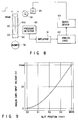
- the change of pressure is detected by the pressure detector 50 connected to the pressure detecting chamber 40b, and a difference between the above pressure and atmospheric pressure is converted to a voltage.
- the voltage is input to an amplifier 51 to be amplified.
- the voltage which is obtained when the lowermost end portion of chip paper 1 is placed at the deepest position S0, is amplified to a motor supplying voltage value by which the rotating speed of the servo motor 12 for driving the delivery roller 11 is the lowest.
- the voltage amplified by the amplifier 51 is input to an analog card 52.
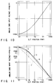
- FIG. 5 is a graph showing the relationship between the slit position where the lowest end portion of chip paper 1 is positioned and the voltage value amplified by the amplifier 51, that is, the analog card input voltage.
- the analog card 52 is a control circuit for approximately converting a non-linear function to a linear function.
- the conversion to the linear function is performed by the following step based on the graph of FIG. 5.
- the non-linear function A is approximated two straight lines C and D.
- the analog card input voltage value at the crossing point between two approximate straight lines C and D is corrected so as to correspond to the analog card input voltage of the linear function B at the same slit position.
- the analog card input voltage value V1 at the crossing point between two straight lines C and D is corrected to the voltage value, e.g., 2V1, corresponding to the analog card input voltage of the linear function B at the same slit position Sa.
- FIG. 6 is a graph showing the relationship between the analog card input voltage input from the amplifier 51 and an analog card output voltage, which is corrected by the analog card 52 and which is output to a servo driver 53.
- the analog card input voltage is converted to the analog card output voltage based on the relationship of FIG. 6.
- FIG. 7 is a graph showing the relationship between the slit position of chip paper and the analog card output voltage converted based on the relationship of FIG. 6. As shown in FIG. 7, the analog card output voltage, which corresponds to the slit position of chip paper, is converted to the linear function.
- the analog card output voltage which is converted based on the slit position of chip paper, is output to the servo driver 53.
- the analog card input voltage value which has the non-linear relationship with the slit position of the reserving chamber 40a of chip paper 1, is approximated two straight lines, and corrected based the relationship shown in FIG. 6.
- two approximate straight lines C and D are converted to one linear function B, so that the analog card output voltage shown in FIG. 7 can be obtained.
- the voltage output from the analog card 52 is input to the servo driver 53 for driving the servo motor 12.
- the rotating speed of the servo motor 12 is controlled in accordance with the output voltage.
- the delivery roller 11 is rotated at a predetermined rotating speed, so that chip paper 1 is delivered from the rolled chip paper 16.
- the rotating speed of the delivery roller 11 can be controlled in accordance with the amount of absorbing and feeding the chip paper 1 in the reserving chamber regardless of the diameter of the roll of the rolled chip paper from which chip paper is delivered. Moreover, the apparatus can be instantaneously started and stopped without applying high load to chip paper 1.
- the internal pressure of the pressure detecting chamber 40b provided at the back of the reserving chamber 40a is changed in accordance with the slit position S0 to Smax of chip paper 1 absorbed and fed in the reserving chamber 40a.
- the change of pressure is detected by the pressure detector 60 connected to the pressure detecting chamber 40b, and a difference between the above pressure and atmospheric pressure is converted to a voltage.
- the voltage is input to an amplifier 61 to be amplified.
- the voltage which is obtained when the lowermost end portion of chip paper 1 is placed at the deepest position S0, is amplified to a motor supplying voltage value by which the rotating speed of the servo motor 35 for driving the winding roller is the highest.
- the voltage amplified by the amplifier 61 is input to an analog card 62.
- FIG. 9 is a graph showing the relationship between the slit position where the lowest end portion of chip paper 1 is positioned and the voltage value amplified by the amplifier 61, that is, the analog card input voltage.
- the analog card 62 converts the analog card input voltage, which has the non-linear relationship with the slit position of FIG. 9, to a linear voltage value to be output. The following will explain the step of such a conversion.
- FIG. 10 is a graph showing that experimental data of FIG. 9 is converted to the relationship between the slit position and the analog card input voltage - Vmax.
- FIG. 11 is a graph showing that the graph of FIG. 10 is converted to the relationship between the slit position and the - analog card input voltage + Vmax.
- the non-linear function E showing the relationship between the slit position and - analog card input voltage + Vmax to the linear function F
- the non-linear function E is approximated two straight lines G and H.
- the analog card input voltage at the cross point between two approximate straight lines G and H is corrected to correspond to the analog card input voltage of the linear function F at the same slit position Sb.
- the analog card input voltage (Vmax - V1) at the cross point between two approximate straight lines G and H is corrected to correspond to the analog card input voltage (Vmax - 2V1) of the linear function F at the same slit position Sb.
- FIG. 12 is a graph showing the relationship between - analog card input voltage + Vmax and the analog card output voltage, which is corrected by an analog card 62 so as to be output to a servo driver 63.
- the analog card input voltage is converted to the analog card output voltage based on the relationship of FIG. 12.
- FIG. 13 is a graph showing the corrected relationship between the slit position of chip paper and the analog card output voltage. As shown in FIG. 13, the analog card output voltage corresponding to the slit position of chip paper is converted to the linear function.
- the analog card input voltage which has the non-linear relationship with the slit position of chip paper absorbed and fed to the reserving chamber, is approximated two straight lines after the analog card input voltage is converted to the voltage - Vmax and the polarity of the voltage is inverted. Moreover, the analog card input voltage is corrected based on the relationship of FIG. 12. As a result, two approximate straight lines is converted to one linear function F, so that the analog card output voltage corresponding to the slit position can be obtained as shown in FIG. 13.
- the voltage output from the analog card 62 is input to the servo driver 63 for driving the servo motor 35.
- the rotating speed of the servo motor 35 is controlled. Then, the winding roller 34 is rotated at a predetermined rotating speed in accordance with the rotating speed of the servo motor 35, so that chip paper 1 is wound around the winding bobbin.
- the rotating speed of the winding roller 34 can be controlled in accordance with the amount of absorbing and feeding chip paper 1 in the reserving chamber regardless of the diameter of the roll of the winding roller 34 by which chip paper is wound. Moreover, the apparatus can be instantaneously started and stopped without applying high load to chip paper 1, and the feed roller 31.
- the use of the apparatus for stably transferring belt-like material of the present invention is not limited to the punching apparatus for forming fine holes in rolled chip paper.
- the present invention can be applied to the supplying apparatus or the winding apparatus, independently.
- the present invention can be applied to the apparatus for printing or processing the other belt-like material, e.g., wrapping paper.
- the apparatus for stably transferring belt-like material of the present invention comprises the absorbing and feeding apparatus for continuously absorbing and feeding the belt-like material in the transferring passage where the belt-like material is transferred.
- the absorbing and feeding apparatus comprises the reserving chamber for absorbing and feeding the belt-like material to be reserved therein, and the pressure detecting chamber connected to the reserving chamber through the slit or the through hole.
- the reserving chamber has the opening portion for absorbing and feeding the belt-like material, and the blower is connected to at the position, which is opposite to the opening portion.
- the blower absorbs the internal air of the reserving chamber, negative pressure is applied to the belt-like material to be passed through the opening portion, so that the belt-like material is absorbed and fed to the reserving chamber.
- the pressure detecting chamber is closed such that pressure of the pressure detecting chamber is changed in accordance with the change of the pressure in the reserving chamber connected to the pressure detecting chamber through the through hole.
- the pressure of the pressure detecting chamber is detected by the pressure detector.
- the pressure of the reserving chamber is changed in accordance with the amount of absorbing and feeding the belt-like material absorbed and fed in the reserving chamber. Due to this, the lowermost end position of the absorbed and fed belt-like material can be correctly detected by detecting the internal pressure of the pressure detecting chamber.
- the amount of supplying the belt-like material of the supplying apparatus or that of winding the belt-like material of the winding apparatus can be controlled.
- the drive voltage of the servo motor for driving the delivery roller or the winding roller is controlled, and the rotating speed of each roller is controlled. Therefore, the amount of supplying the belt-like material of the supplying apparatus or that of winding the belt-like material of the winding apparatus can be appropriately controlled.
- the belt-like material is reserved to the reserving chamber of the absorbing and feeding apparatus, which is provided in the transferring passage, by use of negative pressure before the operation of the apparatus is started. Therefore, even in a case where the belt-like material is instantaneously transferred at the time of staring the apparatus, the load to be applied to the belt-like material can be relaxed by the reserved belt-like material. Due to this, the belt-like material can be prevented from being broken at the time of starting the apparatus. Also, even after the belt-like material is started to be transferred, the belt-like material is reserved in the reserving chamber at substantially the fixed rate.
- an apparatus for stably transferring belt-like material which can be instantaneously started at high speed and stopped. Also, a stable transfer of the belt-like material can be ensured. Due to this, the apparatus can be prevented from being undesirably stopped by the breakage of the belt-like material, so that ability of processing the belt-like material can be improved.
Landscapes
- Manufacturing Of Cigar And Cigarette Tobacco (AREA)
- Replacement Of Web Rolls (AREA)
Applications Claiming Priority (3)
| Application Number | Priority Date | Filing Date | Title |
|---|---|---|---|
| JP1059895 | 1995-01-26 | ||
| JP01059895A JP3363278B2 (ja) | 1995-01-26 | 1995-01-26 | 帯状材の安定走行装置 |
| JP10598/95 | 1995-01-26 |
Publications (3)
| Publication Number | Publication Date |
|---|---|
| EP0723925A2 true EP0723925A2 (de) | 1996-07-31 |
| EP0723925A3 EP0723925A3 (de) | 1997-09-17 |
| EP0723925B1 EP0723925B1 (de) | 2002-06-26 |
Family
ID=11754686
Family Applications (1)
| Application Number | Title | Priority Date | Filing Date |
|---|---|---|---|
| EP96101049A Expired - Lifetime EP0723925B1 (de) | 1995-01-26 | 1996-01-25 | Gerät zum stabilen Übergeben von bahnartigem Material |
Country Status (4)
| Country | Link |
|---|---|
| US (1) | US5697573A (de) |
| EP (1) | EP0723925B1 (de) |
| JP (1) | JP3363278B2 (de) |
| DE (1) | DE69621964T2 (de) |
Cited By (5)
| Publication number | Priority date | Publication date | Assignee | Title |
|---|---|---|---|---|
| EP0858888A3 (de) * | 1997-02-13 | 1999-02-17 | Maschinenfabrik Gietz Ag | Flach-Prägedruckmaschine |
| NL1013194C2 (nl) * | 1999-10-01 | 2001-04-03 | Aremberg Beheer B V I O | Werkwijze voor het bufferen van bandmateriaal, toevoerinrichting voor bandmateriaal en inrichting voor het met bandmateriaal omgeven van producten. |
| WO2002100198A1 (fr) * | 2001-06-08 | 2002-12-19 | Japan Tobacco Inc. | Distributeur de materiau en bande |
| WO2011042047A1 (de) * | 2009-10-06 | 2011-04-14 | Kern Ag | Vorrichtung zum schneiden von papierbahnen |
| EP2594515A3 (de) * | 2011-11-15 | 2016-03-23 | Nittoku Engineering Co., Ltd. | Unterbrochene Filmträgervorrichtung und unterbrochenes Filmträgerverfahren |
Families Citing this family (5)
| Publication number | Priority date | Publication date | Assignee | Title |
|---|---|---|---|---|
| US6082657A (en) * | 1999-02-11 | 2000-07-04 | Powerchip Semiconductor Corp. | Wire-feeding device using logical circuitry and multiple sensors |
| DE10032675B4 (de) * | 2000-07-05 | 2006-06-14 | Aradex Ag | Bahnverarbeitende Maschine |
| JP4090710B2 (ja) * | 2001-06-21 | 2008-05-28 | 株式会社不二鉄工所 | 巻取制御方法 |
| JP6030311B2 (ja) * | 2012-02-13 | 2016-11-24 | 日産自動車株式会社 | 帯状の電池素材の搬送装置および搬送方法 |
| TWI801347B (zh) * | 2016-08-08 | 2023-05-11 | 日商尼康股份有限公司 | 基板處理裝置及基板處理方法 |
Family Cites Families (13)
| Publication number | Priority date | Publication date | Assignee | Title |
|---|---|---|---|---|
| US3203635A (en) * | 1962-07-30 | 1965-08-31 | Burroughs Corp | Servo control system |
| US3223338A (en) * | 1962-08-01 | 1965-12-14 | Fujitsu Ltd | Tape drive mechanism |
| US3785588A (en) * | 1971-11-24 | 1974-01-15 | Bell Telephone Labor Inc | Tape transport reel servo system |
| FR2205888A5 (de) * | 1972-11-07 | 1974-05-31 | Cii | |
| US4025005A (en) * | 1974-09-21 | 1977-05-24 | Agfa-Gevaert, A.G. | Web feeding and collecting apparatus for photographic printers or the like |
| US4030131A (en) * | 1975-08-20 | 1977-06-14 | Honeywell Inc. | Slack tape loader |
| JPS55139654A (en) * | 1979-04-12 | 1980-10-31 | Matsushita Electric Ind Co Ltd | Tape tension control method |
| US4253597A (en) * | 1979-07-09 | 1981-03-03 | Moore Business Forms, Inc. | Loose loop feed control apparatus |
| FR2485224A1 (fr) * | 1980-06-19 | 1981-12-24 | Cii Honeywell Bull | Capteur de position de bande et dispositif de mesure de position incluant ce capteur |
| US4377251A (en) * | 1980-10-08 | 1983-03-22 | King Instrument Corporation | Variable geometry vacuum column |
| US5079569A (en) * | 1991-02-25 | 1992-01-07 | B. Bunch Company, Inc. | Laser printer with paper positioning and tensioning features |
| EP0623432B1 (de) * | 1993-04-08 | 1998-05-20 | Eastman Kodak Company | Vorrichtung zum Transport sowie zum Lochstanzen eines bandförmigen Materials |
| US5505401A (en) * | 1994-03-25 | 1996-04-09 | Lamothe; Richard P. | Machine for manipulating web material |
-
1995
- 1995-01-26 JP JP01059895A patent/JP3363278B2/ja not_active Expired - Fee Related
-
1996
- 1996-01-25 US US08/591,297 patent/US5697573A/en not_active Expired - Fee Related
- 1996-01-25 DE DE69621964T patent/DE69621964T2/de not_active Expired - Fee Related
- 1996-01-25 EP EP96101049A patent/EP0723925B1/de not_active Expired - Lifetime
Cited By (8)
| Publication number | Priority date | Publication date | Assignee | Title |
|---|---|---|---|---|
| EP0858888A3 (de) * | 1997-02-13 | 1999-02-17 | Maschinenfabrik Gietz Ag | Flach-Prägedruckmaschine |
| NL1013194C2 (nl) * | 1999-10-01 | 2001-04-03 | Aremberg Beheer B V I O | Werkwijze voor het bufferen van bandmateriaal, toevoerinrichting voor bandmateriaal en inrichting voor het met bandmateriaal omgeven van producten. |
| WO2002100198A1 (fr) * | 2001-06-08 | 2002-12-19 | Japan Tobacco Inc. | Distributeur de materiau en bande |
| US7204401B2 (en) | 2001-06-08 | 2007-04-17 | Japan Tobacco Inc. | Web material feeding apparatus |
| WO2011042047A1 (de) * | 2009-10-06 | 2011-04-14 | Kern Ag | Vorrichtung zum schneiden von papierbahnen |
| US20120222528A1 (en) * | 2009-10-06 | 2012-09-06 | Kroehnert Rene | Device for cutting paper webs |
| US10106356B2 (en) | 2009-10-06 | 2018-10-23 | Kern Ag | Device for cutting paper webs |
| EP2594515A3 (de) * | 2011-11-15 | 2016-03-23 | Nittoku Engineering Co., Ltd. | Unterbrochene Filmträgervorrichtung und unterbrochenes Filmträgerverfahren |
Also Published As
| Publication number | Publication date |
|---|---|
| DE69621964T2 (de) | 2003-01-09 |
| JPH08196257A (ja) | 1996-08-06 |
| EP0723925B1 (de) | 2002-06-26 |
| US5697573A (en) | 1997-12-16 |
| DE69621964D1 (de) | 2002-08-01 |
| EP0723925A3 (de) | 1997-09-17 |
| JP3363278B2 (ja) | 2003-01-08 |
Similar Documents
| Publication | Publication Date | Title |
|---|---|---|
| US5697573A (en) | Apparatus for stably transferring belt-like material | |
| KR100307429B1 (ko) | 테일실러를내장한권취기 | |
| US4634069A (en) | Winding apparatus for sheet strip | |
| JPS60213653A (ja) | シート排送装置の制御及び調節装置 | |
| EP1894657A2 (de) | Drahtelektrodenzuführvorrichtung für eine Funkenerosionsdrahtschneidemaschine | |
| US4655067A (en) | Panel forming line | |
| ES2208583T3 (es) | Dispositivo para cortar bandas de papel. | |
| JP2632188B2 (ja) | コンベアによりずれ重なり流の形で給排される印刷物の巻取り繰出し装置 | |
| JPH04226840A (ja) | スパーク腐食式切断機の電極をホイールの周りに一巡させる装置 | |
| US5268551A (en) | Wire electrode positioning control device of electrical discharge wire-cutting machine | |
| US5456098A (en) | Process and apparatus for controlling the loading of a processing machine with band-like material | |
| JP4090710B2 (ja) | 巻取制御方法 | |
| JP2005154061A (ja) | テープ類送り装置 | |
| JP3172080B2 (ja) | 枚葉紙給紙ユニット | |
| KR102323112B1 (ko) | 2차전지용 실링테이프 슬리팅 및 권취장치 | |
| JP4642002B2 (ja) | 半導体ウエハの保護テープ切断方法および保護テープ切断装置 | |
| JPS61174054A (ja) | 包装部材供給装置における繰り出し量制御装置 | |
| KR100357938B1 (ko) | 웹 권취장치 | |
| JP2726516B2 (ja) | 給紙装置の制御方法 | |
| JP2930816B2 (ja) | 薄板の送り装置 | |
| CN113353684A (zh) | 一种印刷机收放料装置 | |
| JPH0530044Y2 (de) | ||
| CN219173840U (zh) | 一种复卷机用传动装置 | |
| KR20060133270A (ko) | 회전 엠보싱 및 금박 인쇄장치 | |
| JPH08108969A (ja) | 巻線機張力調整装置 |
Legal Events
| Date | Code | Title | Description |
|---|---|---|---|
| PUAI | Public reference made under article 153(3) epc to a published international application that has entered the european phase |
Free format text: ORIGINAL CODE: 0009012 |
|
| 17P | Request for examination filed |
Effective date: 19960221 |
|
| AK | Designated contracting states |
Kind code of ref document: A2 Designated state(s): DE GB IT |
|
| PUAL | Search report despatched |
Free format text: ORIGINAL CODE: 0009013 |
|
| AK | Designated contracting states |
Kind code of ref document: A3 Designated state(s): DE GB IT |
|
| 17Q | First examination report despatched |
Effective date: 19991222 |
|
| GRAG | Despatch of communication of intention to grant |
Free format text: ORIGINAL CODE: EPIDOS AGRA |
|
| GRAG | Despatch of communication of intention to grant |
Free format text: ORIGINAL CODE: EPIDOS AGRA |
|
| GRAH | Despatch of communication of intention to grant a patent |
Free format text: ORIGINAL CODE: EPIDOS IGRA |
|
| GRAH | Despatch of communication of intention to grant a patent |
Free format text: ORIGINAL CODE: EPIDOS IGRA |
|
| GRAA | (expected) grant |
Free format text: ORIGINAL CODE: 0009210 |
|
| AK | Designated contracting states |
Kind code of ref document: B1 Designated state(s): DE GB IT |
|
| REG | Reference to a national code |
Ref country code: GB Ref legal event code: FG4D |
|
| REF | Corresponds to: |
Ref document number: 69621964 Country of ref document: DE Date of ref document: 20020801 |
|
| PLBE | No opposition filed within time limit |
Free format text: ORIGINAL CODE: 0009261 |
|
| STAA | Information on the status of an ep patent application or granted ep patent |
Free format text: STATUS: NO OPPOSITION FILED WITHIN TIME LIMIT |
|
| 26N | No opposition filed |
Effective date: 20030327 |
|
| PGFP | Annual fee paid to national office [announced via postgrant information from national office to epo] |
Ref country code: GB Payment date: 20060125 Year of fee payment: 11 |
|
| PGFP | Annual fee paid to national office [announced via postgrant information from national office to epo] |
Ref country code: IT Payment date: 20060131 Year of fee payment: 11 Ref country code: DE Payment date: 20060131 Year of fee payment: 11 |
|
| PG25 | Lapsed in a contracting state [announced via postgrant information from national office to epo] |
Ref country code: DE Free format text: LAPSE BECAUSE OF NON-PAYMENT OF DUE FEES Effective date: 20070801 |
|
| GBPC | Gb: european patent ceased through non-payment of renewal fee |
Effective date: 20070125 |
|
| PG25 | Lapsed in a contracting state [announced via postgrant information from national office to epo] |
Ref country code: GB Free format text: LAPSE BECAUSE OF NON-PAYMENT OF DUE FEES Effective date: 20070125 |
|
| PG25 | Lapsed in a contracting state [announced via postgrant information from national office to epo] |
Ref country code: IT Free format text: LAPSE BECAUSE OF NON-PAYMENT OF DUE FEES Effective date: 20070125 |