EP0723064A2 - Rahmenprofil für Fenster, Türen oder Fassaden mit im Brandfall aufschäumendem Baustoff - Google Patents
Rahmenprofil für Fenster, Türen oder Fassaden mit im Brandfall aufschäumendem Baustoff Download PDFInfo
- Publication number
- EP0723064A2 EP0723064A2 EP96100055A EP96100055A EP0723064A2 EP 0723064 A2 EP0723064 A2 EP 0723064A2 EP 96100055 A EP96100055 A EP 96100055A EP 96100055 A EP96100055 A EP 96100055A EP 0723064 A2 EP0723064 A2 EP 0723064A2
- Authority
- EP
- European Patent Office
- Prior art keywords
- profile
- building material
- strip
- frame profile
- recess
- Prior art date
- Legal status (The legal status is an assumption and is not a legal conclusion. Google has not performed a legal analysis and makes no representation as to the accuracy of the status listed.)
- Granted
Links
Images

Classifications
-
- E—FIXED CONSTRUCTIONS
- E06—DOORS, WINDOWS, SHUTTERS, OR ROLLER BLINDS IN GENERAL; LADDERS
- E06B—FIXED OR MOVABLE CLOSURES FOR OPENINGS IN BUILDINGS, VEHICLES, FENCES OR LIKE ENCLOSURES IN GENERAL, e.g. DOORS, WINDOWS, BLINDS, GATES
- E06B3/00—Window sashes, door leaves, or like elements for closing wall or like openings; Layout of fixed or moving closures, e.g. windows in wall or like openings; Features of rigidly-mounted outer frames relating to the mounting of wing frames
- E06B3/04—Wing frames not characterised by the manner of movement
- E06B3/263—Frames with special provision for insulation
- E06B3/26301—Frames with special provision for insulation with prefabricated insulating strips between two metal section members
-
- E—FIXED CONSTRUCTIONS
- E06—DOORS, WINDOWS, SHUTTERS, OR ROLLER BLINDS IN GENERAL; LADDERS
- E06B—FIXED OR MOVABLE CLOSURES FOR OPENINGS IN BUILDINGS, VEHICLES, FENCES OR LIKE ENCLOSURES IN GENERAL, e.g. DOORS, WINDOWS, BLINDS, GATES
- E06B5/00—Doors, windows, or like closures for special purposes; Border constructions therefor
- E06B5/10—Doors, windows, or like closures for special purposes; Border constructions therefor for protection against air-raid or other war-like action; for other protective purposes
- E06B5/16—Fireproof doors or similar closures; Adaptations of fixed constructions therefor
- E06B5/162—Fireproof doors having windows or other openings, e.g. for permitting ventilation or escape
-
- E—FIXED CONSTRUCTIONS
- E06—DOORS, WINDOWS, SHUTTERS, OR ROLLER BLINDS IN GENERAL; LADDERS
- E06B—FIXED OR MOVABLE CLOSURES FOR OPENINGS IN BUILDINGS, VEHICLES, FENCES OR LIKE ENCLOSURES IN GENERAL, e.g. DOORS, WINDOWS, BLINDS, GATES
- E06B3/00—Window sashes, door leaves, or like elements for closing wall or like openings; Layout of fixed or moving closures, e.g. windows in wall or like openings; Features of rigidly-mounted outer frames relating to the mounting of wing frames
- E06B3/04—Wing frames not characterised by the manner of movement
- E06B3/263—Frames with special provision for insulation
- E06B2003/26394—Strengthening arrangements in case of fire
-
- E—FIXED CONSTRUCTIONS
- E06—DOORS, WINDOWS, SHUTTERS, OR ROLLER BLINDS IN GENERAL; LADDERS
- E06B—FIXED OR MOVABLE CLOSURES FOR OPENINGS IN BUILDINGS, VEHICLES, FENCES OR LIKE ENCLOSURES IN GENERAL, e.g. DOORS, WINDOWS, BLINDS, GATES
- E06B3/00—Window sashes, door leaves, or like elements for closing wall or like openings; Layout of fixed or moving closures, e.g. windows in wall or like openings; Features of rigidly-mounted outer frames relating to the mounting of wing frames
- E06B3/04—Wing frames not characterised by the manner of movement
- E06B3/263—Frames with special provision for insulation
- E06B2003/26396—Frames with special provision for insulation specially adapted for sheet metal frames
Definitions
- the invention relates to a frame profile for windows, doors or facades, with an interior and an exterior, each closed in cross section metal hollow profile, which have at least one fire-resistant connector between them and are firmly connected.
- a frame profile with the aforementioned features is known from DE-U-91 08 751. It meets standardized requirements for fire protection components. It is a composite profile, a further metal hollow profile is arranged between the metal hollow profiles and these connected fire-resistant connectors. This frame profile is inserted between two insulating glass panes arranged in the same plane and has no free end face, so it does not adjoin a rebate space.
- a fire protection door with a surrounding frame is known, in the front side of which is assigned to the rebate space an open groove is incorporated.
- the groove is profiled in a dovetail shape and is fitted with an insertable strip which clasps around the front edges of the groove and is provided with a hollow chamber.
- the frame is made of specially shaped profiles, which must be dovetailed in a complex manner on the rebate side.
- special door panels are required, which also cover the known frame on the rebate side. The forehead or rabbet side view of the known fire door is consequently and because of the provided bar inconsistent.
- the invention has for its object to improve a frame profile with the features mentioned so that a handsome appearance of the rebate side surface of the frame profile is achieved and at the same time a permanent fire protection function of the frame profile is ensured.
- the connector for forming a recess running longitudinally in the profile of at least one of the rebate space or end wall surfaces of the hollow metal profiles protrudes that one of the rebate space or. is arranged end face wall surfaces and the recess covering bar that foaming building material is housed in the recess in the event of fire, and that the bar melts in the event of fire before reaching the foaming temperature of the building material and thereby allows heat to enter the building material.
- the frame profile is specially adapted to fire protection tasks. It is comparatively insensitive to fire, because the metal hollow profiles have a very good heat stability and the fire-resistant connector ensures that the dimensional stability of the entire frame profile is guaranteed even with high fire safety requirements. It is only necessary to keep the fire-resistant connector slightly shorter in the connecting plane of the two hollow metal profiles vertically to the rebate space than this itself in order to create the recess for accommodating the foaming building material.
- the bar protects the building material inserted in this recess and ensures the visually appealing appearance of the frame profile from the rebate side. An optical treatment of the surface of the fire-resistant connector that is optically visible in the absence of a strip is not necessary.
- the strip covering the building material covers the frame profile on the rebate side, at least in the area of this building material.
- all requirements for the visual appearance of the frame profile can be met, namely geometric and colored designs of the strip, such as also any surface structures.
- the bar ensures protection of the foaming building material. Accidental or simply malicious access to the foaming building material is not possible.
- the melting of the strip leads to the foaming building material being subjected to the heat or energy required for the foaming, so that the fire protection function is guaranteed.
- skirting board is directly adjacent to the building material, this ensures that heat is transferred to the foaming building material without delay. There is no undue delay in foaming and therefore no unintentional hindrance to the fire protection effect.
- the frame profile can be advantageously designed in that the bar and the building material are assembled into a handling unit. As a result, it is possible to assemble the molding and the building material at the factory in order to achieve a functional unit. On the one hand it is ensured that the foaming building material and the strip always have the structurally predetermined relative position to each other and on the other hand it is achieved that both are assembled together with the frame profile, so that the installation or attachment of the foaming building material is not carried out incorrectly can. In this context, it is particularly important to check that the strip is properly seated on the frame profile, which not only ensures that the frame profile looks good, but also that the fire protection function is guaranteed by the foaming building material.
- the frame profile in such a way that the strip has two surrounding strips projecting at right angles on the profile side, the space between which is filled with the building material.
- the two surrounding ledges projecting on the profile side form a defined installation space for the foaming building material and thus also a protective space for this. This is necessary for room assembly operation on the frame profile, if this is for assembly with others Frame profiles is assembled or if it is assembled with further frame profiles, provided that the foaming building material is already attached. Its mechanically sensitive structure could otherwise lead to it being damaged.
- the perpendicularity of the projecting surrounding strips allows the strip to be inserted into a conventional recess with a rectangular or square cross section.
- the two surrounding strips hold a cover cladding the building material on the profile side.
- This cover cladding the building material not only protects it from the outside, but can also hold it in its installed position, for example by pinching it. In this way it is easily possible, for example, to hold slightly pre-compressed, foaming building material.
- the frame profile with its surrounding strips can be designed in such a way that the two surrounding strips are integrally connected to one another to form a rectangular cross-section by a cover wall surrounding the building material.
- the one-piece construction of the cover wall with the other parts of the strip leads to a substantial stabilization of the component.
- the foaming building material is completely enclosed and protected accordingly.
- the rectangular cross-section of the area defined by the two surrounding strips and the one-piece cover wall corresponds to a conventional, rectangular, cross-section-shaped recess and thus an optimal use of the existing construction volume.
- the recess is completely filled and the strip lies flat against the rebate-side wall of the frame profile or can be arranged flush with the rebate-side profile surfaces if it does not cover the rebate-side profile surfaces .
- the result is an optimal use of space and an appealing exterior.
- a frame profile can be designed in such a way that the bar has a retaining bar projecting at right angles on the profile side, on each side of which foaming building material is arranged. This simplifies the structure of the bar. It is particularly independent of the dimensioning of the width of the continuous recess and can be used more universally.
- a simple attachment of the bar to the frame profile can be achieved in that the holding bar arranged in the center of the recess is pressed through the recess into a holding groove of the frame profile.
- a frame profile can be developed in that the bar and the building material fill the recess.
- the available cross-section is optimally used. Since the bar with the foaming building material fills the recess formed by the recess of the connector between the hollow metal profiles, on the one hand the connection strength of the two hollow metal profiles is only slightly impaired, but on the other hand a structurally simple adjustment of the cross section of the frame profile is achieved.
- the bar In order to improve the visual impression of the frame profile from the rebate side, it is advantageous if the bar covers all profile wall surfaces on the rebate side.
- the strip then also simultaneously provides mechanical protection for the surfaces of the hollow metal profiles on the rebate side.
- the strip has a flat, first angled leg, which covers all of the rebate-side profile wall surfaces, and a second angled leg, which is perpendicular to it, and which covers a fold-over surface of a hollow metal profile facing the rebate area.
- first angled leg which covers all of the rebate-side profile wall surfaces
- second angled leg which is perpendicular to it, and which covers a fold-over surface of a hollow metal profile facing the rebate area.
- the frame profile To adapt the frame profile to conventional frame environments, it is designed so that the outer profile of the hollow metal profile is provided with a cladding on the outside of the room in a flush fold-side connection to the strip covering the foaming building material.
- the bar covering the foaming material is thus included in a cladding of the outer metal hollow profile, so that a complete adaptation to conventional outside areas can be achieved. It is not recognizable from the outside that the frame profile is a special fire protection profile. Since the hollow metal profiles also have considerable stability, the frame profile is correspondingly burglar-resistant.
- the frame profile can be designed in such a way that the hollow metal profile inside the profile has at least one recess on the inside of the room, in which building material which is foaming in the event of a fire is arranged. Improved fire protection is achieved.
- the additional building material provided for this purpose is preferably arranged on the rebate side, where it is covered by another frame component, namely by a rollover of a wing, so that the building material which foams up in the event of a fire seals the gap between the wing rollover and the frame profile parallel to the frame plane.
- the frame profile can furthermore be designed such that the building material arranged in the recess of the hollow metal profile inside the profile is covered with a strip leg of the strip on the rebate area side that is flush with this profile and / or that the strip has predetermined melting points.
- the covering of the building material provides a corresponding mechanical protection during normal handling of the window and ensures a handsome appearance due to the strip leg lying flush with the profile.
- the cost of covering is kept small, since no separate strip part has to be used, but the covering strip which is required anyway only needs to have an additional covering leg.
- the building material that foams up in the event of a fire is able to break the strip at a time when the strip may only be in places has melted. As a result of this breaking open, faster sealing is achieved.
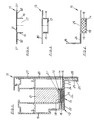
- the frame profile 10 shown in FIG. 1 consists of two hollow metal profiles 19, 20 which are arranged at a distance from one another and are held firmly together by a connector 21. The three aforementioned parts are glued together, for example.
- Each of the metal hollow profiles 19, 20 has a wall surface 22, 23 facing the rebate space 11.
- the hollow metal profile 20 also has a rollover 28 with a rollover surface 25 facing the rebate area 11.
- All the wall surfaces 22, 23, 25 facing the rebate space 11 are covered by a strip 15 which has a flat angled leg 24 which is smooth towards the rebate space 11 and a right-angled leg 26 which is also arranged at right angles to the rebate space 11.
- the two angle legs 24, 26 are comparatively close to the profile wall surfaces 22, 23, 25, so that they are not very bulky. They completely clad the metal hollow profiles 19, 20 on the rebate side.
- the frame profile 10 is a frame spar of a frame. Its metal hollow profile 20 on the outside of the frame is provided on the outside of the frame with a cladding 27 which, for example, consists of plastic and is fastened in the usual way.
- the cladding 27 encompasses the rollover 28 from the outside up to the rollover surface 25, so that it is flush with the angle leg 26 of the bar 15 lies. This results in a complete cladding of the entire frame profile on the outside of the frame and on the rebate side.
- the strip 15 has, from its angle leg 24, profile strips 16 projecting at right angles on the profile side. These cover strips 16 stabilize the strip 15 and engage in a recess 13 in the frame profile 10, which is produced in that the connector 21 is kept shorter in the plane of representation perpendicular to the rebate space 11 when the metal hollow profiles 19.20. Their rebate-side wall surfaces 22, 23 thus project over the rebate-side wall surface 21 of the connector 21.
- the strip 15 can be fixed on the frame profile 10, for example by clamping or gluing. Screwing through the angle leg 24 into the connector 21 is also possible, e.g. at the screw point marked by 29.
- the space between the surrounding strips 16 is essentially filled by building material 14 which foams in the event of a fire.
- building material 14 is temperature-sensitive and experiences a considerable increase in volume if its temperature or its ambient temperature increases to a value that experience has shown to occur in the event of a fire.
- the building material contains a temperature-sensitive substance which gasifies at a predetermined temperature and thereby increases the volume of the building material many times over.
- Such a building material is usually somewhat pre-compressed in order to keep its installation volume small.
- a cover 18 is provided between the surrounding strips 16, which engages in a form-fitting manner in grooves which are provided on the surrounding strips 16 on the construction material side.
- the installation of the building material 14 is overall such that it bears directly on the profile-side inner wall of the angle leg 24. An intermediate volume that transmits poor energy is thereby avoided.
- the cover strip 15 must be such that it does not hinder the foaming. It is therefore made of a plastic whose melting temperature is lower than the temperature from which the building material foams. When the plastic of the strip 15 is melted, heat access to the building material 14 is made possible, so that it can expand through those areas of the strip 15 from which the plastic has melted away. The foaming of the building material can help push the melted plastic away.
- FIG. 2 shows a cross-sectional configuration of the strip 15 with two right-angled projecting surrounding strips 16, which in turn are integrally connected to one another by a cover wall 18 '.
- the result is an overall rectangular cross section, which is adapted to the cross section of the recess 13, so that the recess 13 is completely filled.
- the covering wall 18 ', together with the surrounding strips 16, stabilizes the strip 15 and encloses the building material 14 securely, so that it can be introduced with high pre-compression, which, in the event of a melting of the angled leg 24 in the event of a fire, contributes to the foaming building material 14 quickly entering can penetrate the rebate 16.
- FIG. 3 shows a configuration of a cross section of a strip 15 corresponding to the configuration according to FIG. 2, but only a single smooth strip leg 30 is provided to cover the two profile wall surfaces 22, 23 on the rebate space side.
- the building material that foams up in the event of a fire is not shown, but is present.
- the cover strip 15 consists of a cover leg 31, on the outer edges 31 'of which surround strips 16 are fastened, each of which has a fastening leg 32 which is parallel to the cover leg 31.
- These Design is production-related, but also permits the arrangement of building material 14 which foams up in the event of a fire in the intermediate space 17 between the surrounding strips 16.
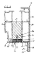
- FIG. 5 shows a cross section through a frame profile 10, for the details of which reference is made to FIG. 1 insofar as the same reference numerals are entered in FIG.
- the strip 15 assembled with this frame profile 10 has a retaining strip 16 'projecting at right angles on the profile side with a free ribbed end 33 which is pressed into a retaining groove 34 of the connector.
- the angle leg 24 lies tightly against the profile wall surfaces 22, 23.
- the holding strip 16 'foaming building material 14 is arranged on both sides. This is preferably designed to be dimensionally stable. Since only a single retaining strip 16 'has to be accommodated in the region of the recess 13, the remaining space of the recess 13 is available for the arrangement of foaming building material 14 or the recess 13 is reduced.
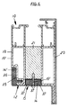
- the frame profile 10 shown in cross section in FIG. 6 corresponds to the profile shown in FIG. 5 with regard to the profiling of the metal hollow profiles 19, 20 and the connector 21 located between them.
- the building material 14 which foams up in the event of a fire and the formation of the strip 15 on the rebate side side with the retaining strip 16 'projecting on the connector side is also unchanged.
- the hollow metal profile 19 inside the profile is provided in the vicinity of the rebate space with a recess 35, which has also already been shown, for example, in FIG. 5, but which is filled in FIG. 6 with building material 14 'which foams in the event of a fire.
- building material 14 ' which foams in the event of a fire.
- this area there is usually a flap overlap inside the room.
- the frame-parallel gap between this sash overlap and the adjacent area of the frame profile 10 can be sealed by the building material 14 'foaming.
- the building material 14 'can also partially fill up the rebate area. So this partly also help to fill the rebate area.
- the strip 15 was provided with a strip leg 36 which is flush with the inner surface 19' of the frame.
- This strip leg 36 is at right angles and in one piece with the strip 15, which completely covers the frame profile 10 towards the rebate space, that is to say covers the side wall 12 of the frame profile 10 on the rebate space side.
- the strip 15 is provided with predetermined melting points 37.
- Two predetermined melting points 37 are located immediately adjacent to the centrally arranged holding strip 16 ', and a further predetermined melting point is located in the vicinity of the hollow metal profiles 19, 20.
- the strip 15 melts, preferably at the predetermined melting points 37. This makes it easier for the foaming building material 14 to push away the strip areas located between predetermined breaking points 37 and accordingly contributes to the faster filling of the rebate space.
Landscapes
- Engineering & Computer Science (AREA)
- Civil Engineering (AREA)
- Structural Engineering (AREA)
- Special Wing (AREA)
- Wing Frames And Configurations (AREA)
- Paper (AREA)
- Glass Compositions (AREA)
- Securing Of Glass Panes Or The Like (AREA)
Abstract
Description
- Die Erfindung bezieht sich auf ein Rahmenprofil für Fenster, Türen oder Fassaden, mit einem rauminnenseitigen und einem raumaußenseitigen, jeweils im Querschnitt geschlossenen Metallhohlprofil, die zwischen sich mindestens einen brandbeständigen Verbinder aufweisen und fest miteinander verbunden sind.
- Ein Rahmenprofil mit den vorgenannten Merkmalen ist aus DE-U-91 08 751 bekannt. Es genügt genormten Anforderungen an Feuerschutzbauteile. Es handelt sich um ein Verbundprofil, zwischen dessen Metallhohlprofilen und sich an diese anschließenden brandbeständigen Verbinder ein weiteres Metallhohlprofil angeordnet ist. Dieses Rahmenprofil wird zwischen zwei in derselben Ebene angeordneten Isolierglasscheiben eingesetzt und hat keine freie Stirnseite, grenzt also nicht an einen Falzraum an.
- Aus der DE-A-34 23 550 ist eine Feuerschutztür mit einem umlaufenden Rahmen bekannt, in dessen dem Falzraum zugeordneten Stirnseite eine offene Nut eingearbeitet ist. Die Nut ist schwalbenschwanzförmig profiliert und mit einer einsteckbaren Leiste besetzt, welche die stirnseitigen Kanten der Nut umklammert und mit einer Hohlkammer versehen ist. In der Hohlkammer befindet sich ein hitzeaufschäumendes Material, welches die Leiste bei Hitzeeinwirkung zerstört. Für diese Feuerschutztür ist es erforderlich, daß der Rahmen aus besonders geformten Profilen hergestellt wird, die falzraumseitig in aufwendiger Weise schwalbenschwanzförmig profiliert sein müssen. Außerdem sind besondere Türbleche erforderlich, die den bekannten Rahmen auch falzraumseitig abdecken. Die stirn-bzw. falzraumseitige Ansicht der bekannten Feuerschutztür ist infolgedessen und wegen der vorgesehenen Leiste uneinheitlich.
- Demgegenüber liegt der Erfindung die Aufgabe zugrunde, ein Rahmenprofil mit den eingangs genannten Merkmalen so zu verbessern, daß ein ansehnliches Äußeres der falzseitigen Fläche des Rahmenprofils erreicht und zugleich eine dauerhafte Brandschutzfunktion des Rahmenprofils sichergestellt wird.
- Diese Aufgabe wird dadurch gelöst, daß der Verbinder zur Bildung einer im Profil längsdurchlaufenden Ausnehmung von mindestens einer der falzraum- bzw. stirnseitigen Wandflächen der Metallhohlprofile zurücksteht, daß eine die falzraum-bzw. stirnseitigen Wandflächen und die Ausnehmung abdeckende Leiste angeordnet ist, daß in der Ausnehmung im Brandfall aufschäumender Baustoff untergebracht ist, und daß die Leiste im Brandfall vor dem Erreichen der Aufschäumtemperatur des Baustoffs schmilzt und dabei den Wärmezutritt zum Baustoff ermöglicht.
- In diesem Fall ist das Rahmenprofil an Brandschutzaufgaben besonders angepaßt. Es ist vergleichsweise brandunempfindlich, weil die Metallhohlprofile eine sehr gute Hitzestabilität besitzen und der brandbeständige Verbinder dafür sorgt, daß die Formstabilität des gesamten Rahmenprofils auch bei hohen Anforderungen an die Brandsicherheit gewährleistet bleibt. Es ist lediglich erforderlich, den brandbeständigen Verbinder in der Verbindungsebene der beiden Metallhohlprofile vertikal zum Falzraum etwas kürzer zu halten, als diese selbst, um die Ausnehmung zur Unterbringung des aufschäumenden Baustoffs zu schaffen. Die Leiste schützt den in dieser Ausnehmung eingebrachten Baustoff und gewährleistet das optisch ansprechende Aussehen des Rahmenprofils von der Falzraumseite her. Eine optische Behandlung der bei nichtvorhandener Leiste optisch sichtbaren Fläche des brandbeständigen Verbinders ist nicht erforderlich.
- Die den Baustoff abdeckende Leiste verkleidet das Rahmenprofil falzraumseitig zumindest im Bereich dieses Baustoffs. Durch die Auswahl des Werkstoffs und des Aussehens der abdeckenden Leiste können alle Anforderungen an das optische Erscheinungsbild des Rahmenprofils erfüllt werden, nämlich geometrische und farbliche Gestaltungen der Leiste, wie auch etwaige Oberflächenstrukturierungen. Des weiteren wird durch die Leiste ein Schutz des aufschäumenden Baustoffs gewährleistet. Zufälliger oder einfach böswilliger Zugriff auf den aufschäumenden Baustoff sind nicht möglich. Das Schmelzen der Leiste führt zu einer Beaufschlagung des aufschäumenden Baustoffs mit der für das Aufschäumen erforderlichen Wärme bzw. Energie, so daß die Brandschutzfunktion gewährleistet ist.
- Wenn die Leiste an den Baustoff direkt angrenzt, ist für eine verzögerungsfreie Übertragung der Wärme auf den aufschäumenden Baustoff gewährleistet. Es tritt keine ungebührliche Verzögerung der Aufschäumung und damit keine unbeabsichtigte Behinderung der Brandschutzwirkung ein.
- Das Rahmenprofil kann dadurch vorteilhaft ausgestaltet sein, daß die Leiste und der Baustoff zu einer Handhabungseinheit zusammengebaut sind. Es ist infolgedessen möglich, die Leiste und den Baustoff fabrikseitig zusammenzubauen, um eine Funktionseinheit zu erreichen. Zum einen ist gewährleistet, daß der aufschäumende Baustoff und die Leiste stets die konstruktiv vorbestimmte relative Stellung zueinander haben und zum anderen wird erreicht, daß beide gemeinsam mit dem Rahmenprofil zusammengebaut werden, so daß der Einbau bzw. der Anbau des aufschäumenden Baustoffs nicht fehlerhaft durchgeführt werden kann. Hierbei ist insbesondere die Kontrolle des bestimmungsgemäßen Sitzes der Leiste am Rahmenprofil von Bedeutung, welche nicht nur bewirkt, daß die Optik des Rahmenprofils stimmt, sondern auch, daß zugleich die Brandschutzfunktion durch den aufschäumenden Baustoff gewährleistet ist.
- Es ist vorteilhaft, das Rahmenprofil so auszubilden, daß die Leiste zwei profilseitig rechtwinklig vorspringende Umfassungsleisten hat, deren Zwischenraum mit dem Baustoff ausgefüllt ist. Die beiden profilseitig vorspringenden Umfassungsleisten bilden einen definierten Einbauraum für den aufschäumenden Baustoff und damit zugleich auch einen Schutzraum für diesen. Das ist für den Raummontagebetrieb am Rahmenprofil erforderlich, wenn dieses für den Zusammenbau mit weiteren Rahmenprofilen konfektioniert wird oder wenn es mit weiteren Rahmenprofilen zusammengebaut wird, sofern der aufschäumende Baustoff dabei bereits angebracht ist. Dessen mechanisch empfindliche Struktur könnte sonst dazu führen, daß er beschädigt wird. Die Rechtwinkligkeit der vorspringenden Umfassungsleisten gestattet das Einsetzen der Leiste in eine herkömmliche, im Querschnitt rechteckige oder quadratische Ausnehmung.
- In Ausgestaltung der vorbeschriebenen Ausführungsform ist es vorteilhaft, daß die beiden Umfassungsleisten profilseitig eine den Baustoff verkleidende Abdeckung halten. Diese den Baustoff verkleidende Abdeckung schützt ihn nicht nur nach außen hin, sondern kann ihn auch in seiner Einbaulage festhalten, indem er ihn beispielsweise einklemmt. Auf diese Weise ist es beispielsweise einfach möglich, leicht vorkomprimierten aufschäumenden Baustoff zu haltern.
- Des weiteren kann das Rahmenprofil mit seinen Umfassungsleisten so ausgebildet sein, daß die beiden Umfassungsleisten profilseitig durch eine den Baustoff umschließende Abdeckwand einstückig miteinander zu einem rechteckigen Querschnitt verbunden sind. Die Einstückigkeit der Abdeckwand mit den übrigen Teilen der Leiste führt zu einer wesentlichen Stabilisierung des Bauteils. Der aufschäumende Baustoff ist vollständig umschlossen und entsprechend geschützt. Der rechteckige Querschnitt des von den beiden Umfassungsleisten und der einstückigen Abdeckwand definierten Bereichs entspricht einer üblichen im Querschnitt rechteckigen durchlaufenden Ausnehmung und somit einer optimale Ausnutzung des vorhandenen Bauvolumens.
- Wenn die Leiste mit den beiden profilseitig vorspringenden Umfassungsleisten vollständig in die Ausnehmung eingreift, ist die Ausnehmung vollständig ausgefüllt und die Leiste liegt flach an der falzseitigen Wand des Rahmenprofils an bzw. kann bündig mit den falzseitigen Profilflächen angeordnet werden, wenn sie die falzseitigen Profilflächen nicht abdeckt. Es ergibt sich eine optimale Raumausnutzung und ein ansprechendes Äußeres.
- Ein Rahmenprofil kann so ausgebildet sein, daß die Leiste eine profilseitig rechtwinklig vorspringende Halteleiste hat, auf deren beiden Seiten jeweils aufschäumender Baustoff angeordnet ist. Hierdurch wird der Aufbau der Leiste vereinfacht. Sie ist insbesondere unabhängig von der Dimensionierung der Breite der durchlaufenden Ausnehmung und insoweit universeller einsetzbar.
- Eine einfache Befestigung der Leiste am Rahmenprofil kann dadurch erreicht werden, daß die in der Ausnehmung mittig angeordnete Halteleiste durch die Ausnehmung hindurch in eine Haltenut des Rahmenprofils eingepreßt ist.
- Ein Rahmenprofil kann dadurch weitergebildet werden, daß die Leiste und der Baustoff die Ausnehmung ausfüllen. Es entsteht eine optimale Ausnutzung des zur Verfügung stehenden Querschnitts. Da die Leiste mit dem aufschäumenden Baustoff die Ausnehmung ausfüllt, die durch den Rücksprung des Verbinders zwischen die Metallhohlprofile ausgebildet ist, wird einerseits die Verbindungsfestigkeit der beiden Metallhohlprofile nur in geringem Maße beeinträchtigt, andererseits aber eine konstruktiv einfache Anpassung des Querschnitts des Rahmenprofils erreicht.
- Zur Verbesserung des optischen Eindrucks des Rahmenprofils von der Falzraumseite her ist es vorteilhaft, wenn die Leiste alle falzraumseitigen Profilwandflächen verkleidet. Die Leiste nimmt dann zugleich auch einen mechanischen Schutz der falzraumseitigen Flächen der Metallhohlprofile.
- Letzteres ist insbesondere dann der Fall, wenn die Leiste einen ebenen, alle falzraumseitigen Profilwandflächen abdeckenden ersten Winkelschenkel und einen dazu rechtwinkligen, eine dem Falzraum zugewendete Überschlagfläche eines Metallhohlprofils abdeckenden zweiten Winkelschenkel aufweist. Bei einer derartigen Ausbildung der Leiste sind nur zwei glatte bzw. ebene, im Winkel zueinander angeordnete Flächen vorhanden, die einen optisch hervorragenden Eindruck ergeben.
- Zur Anpassung des Rahmenprofils an übliche Rahmenumgebungen wird es so ausgebildet, daß das profiläußere Metallhohlprofil raumaußenseitig in bündigem falzseitigen Anschluß an die den aufschäumenden Baustoff abdeckende Leiste mit einer Verkleidung versehen ist. Die den aufschäumenden Werkstoff abdeckende Leiste wird also in eine Verkleidung des profiläußeren Metallhohlprofils mit einbezogen, so daß eine vollständige Anpassung an übliche Außenbereiche erreicht werden kann. Es ist von außen nicht erkennbar, daß es sich bei dem Rahmenprofil um ein spezielles Brandschutzprofil handelt. Da die Metallhohlprofile zugleich auch eine erhebliche Stabilität aufweisen, ist das Rahmenprofil entsprechend einbruchhemmend.
- Das Rahmenprofil kann so ausgebildet werden, daß das profilinnere Metallhohlprofil rauminnenseitig mindestens einen Rücksprung aufweist, in dem im Brandfall aufschäumender Baustoff angeordnet ist. Es wird ein verbesserter Brandschutz erreicht. Der dafür vorgesehene zusätzliche Baustoff wird vorzugsweise falzraumseitig angeordnet, wo eine Überdeckung durch ein anderes Rahmenbauteil stattfindet, nämlich durch einen Überschlag eines Flügels, so daß der im Brandfall aufschäumende Baustoff den der Rahmenebene parallelen Spalt zwischen Flügelüberschlag und Rahmenprofil abdichtet.
- Das Rahmenprofil kann des weiteren so ausgestaltet sein, daß der im Rücksprung des profilinneren Metallhohlprofils angeordnete Baustoff mit einem zu diesem Profil bündig liegenden Leistenschenkel der falzraumseitigen Leiste abgedeckt ist und/oder daß die Leiste Sollschmelzstellen aufweist. Die Abdeckung des Baustoffs bewirkt einen entsprechenden mechanischen Schutz bei normaler Handhabung des Fensters und sorgt wegen des mit dem Profil bündig liegenden Leistenschenkels für ein ansehnliches Äußeres. Der Abdeckungsaufwand wird klein gehalten, da kein separates Leistenteil eingesetzt werden muß, sondern die ohnehin erforderliche abdeckende Leiste lediglich einen zusätzlichen Abdeckschenkel aufzuweisen braucht. Infolge der Sollschmelzstellen vermag der im Brandfall aufschäumende Baustoff die Leiste zu einem Zeitpunkt aufzubrechen, zu dem die Leiste möglicherweise nur stellenweise geschmolzen ist. Infolge dieses Aufbrechens wird ein schnelleres Abdichten erreicht.
- Die Erfindung wird anhand von in der Zeichnung dargestellten Ausführungsbeispielen erläutert. Es zeigt:
- Fig.1
- einen Querschnitt durch ein Rahmenprofil mit einer Leiste, die falzraumseitige Profilflächen abdeckt und aufschäumenden Baustoff aufweist,
- Fig.2 bis 4
- unterschiedliche Querschnittsgestaltungen der den aufschäumenden Baustoff abdeckenden Leiste, und
- Fig.5,6
- der Fig.1 entsprechende Darstellungen weiterer Ausführungsformen von Leisten.
- Der in Fig.1 dargestellte Rahmenprofil 10 besteht aus zwei Metallhohlprofilen 19,20, die mit Abstand voneinander angeordnet sind und durch einen Verbinder 21 fest zusammengehalten werden. Die drei vorgenannten Teile werden beispielsweise miteinander verklebt. Jedes der Metallhohlprofile 19,20 hat eine dem Falzraum 11 zugewendete Wandfläche 22,23. Das Metallhohlprofil 20 hat außerdem einen Überschlag 28 mit einer den Falzraum 11 zugewendeten Überschlagfläche 25.
- Sämtliche dem Falzraum 11 zugewendeten Wandflächen 22, 23,25 werden durch eine Leiste 15 abgedeckt, die einen ebenen, zum Falzraum 11 hin glatten Winkelschenkel 24 und einen rechtwinklig dazu angeordneten, zum Falzraum 11 hin ebenfalls glatten Winkelschenkel 26 aufweist. Die beiden Winkelschenkel 24,26 sind vergleichsweise dicht an den Profilwandflächen 22, 23,25 an, so daß sie wenig auftragen. Sie verkleiden die Metallhohlprofile 19,20 falzraumseitig vollständig.
- Das Rahmenprofil 10 ist ein Rahmenholm eines Blendrahmens. Sein rahmenaußenseitiges Metallhohlprofil 20 ist rahmenaußenseitig mit einer Verkleidung 27 versehen, die beispielsweise aus Kunststoff besteht und in üblicher Weise befestigt wird. Insbesondere umgreift die Verkleidung 27 den Überschlag 28 von außen bis auf die falzraumseitige Überschlagfläche 25, so daß er dort bündig mit dem Winkelschenkel 26 der Leiste 15 liegt. Es ergibt sich eine vollständige rahmenaußenseitige und falzraumseitige Verkleidung des gesamten Rahmenprofils. Man kann damit eine optimale optische Anpassung des Rahmenprofils 10 an alle denkbaren Einsatzzwecke erreichen, weil die Verkleidung 27 und auch die Leiste 15 in ihrer optischen Erscheinung durch Wahl des Werkstoffs und durch Wahl von Farbe und Oberflächenstruktur weitestgehend angepaßt werden können.
- Die Leiste 15 hat von ihrem Winkelschenkel 24 profilseitig rechtwinklig vorspringende Umfassungsleisten 16. Diese Umfassungsleisten 16 stabilisieren die Leiste 15 und greifen in eine Ausnehmung 13 des Rahmenprofils 10 ein, die dadurch hergestellt ist, daß der Verbinder 21 in Darstellungsebene senkrecht zum Falzraum 11 kürzer gehalten ist, als die Metallhohlprofile 19,20. Deren falzraumseitige Wandflächen 22, 23 springen also gegenüber der falzraumseitigen Wandfläche 21 des Verbinders 21 vor.
- Mit den Umfassungsleisten 16 kann die Leiste 15 am Rahmenprofil 10 festgelegt werden, beispielsweise durch Einklemmen oder durch Einkleben. Auch eine Verschraubung durch den Winkelschenkel 24 in den Verbinder 21 ist möglich, z.B. an der durch 29 gekennzeichneten Einschraubstelle.
- Der Raum zwischen den Umfassungsleisten 16 ist im wesentlichen von im Brandfall aufschäumendem Baustoff 14 ausgefüllt. Derartiger Baustoff 14 ist temperatursensibel und erfährt eine erhebliche Volumenvergrößerung, wenn sich seine Temperatur bzw. seine Umgebungstemperatur auf einen Wert vergrößert, der erfahrungsgemäß im Brandfall auftritt. Das wird in bekannter Weise dadurch erreicht, daß der Baustoff eine temperaturempfindliche Substanz enthält, die bei vorbestimmter Temperatur vergast und dadurch das Volumen des Baustoffs um ein Vielfaches vergrößert. Ein derartiger Baustoff ist in der Regel etwas vorkomprimiert, um sein Einbauvolumen kleinzuhalten. Infolgedessen ist gemäß Fig.l zwischen den Umfassungsleisten 16 eine Abdeckung 18 vorgesehen, die formschlüssig in Nuten eingreift, welche baustoffseitig an den Umfassungsleisten 16 vorgesehen sind. Der Einbau des Baustoffs 14 ist insgesamt so, daß dieser direkt an der profilseitigen Innenwand des Winkelschenkels 24 anliegt. Ein schlecht Energie übertragendes Zwischenvolumen wird dadurch vermieden.
- Damit der aufschäumende Baustoff 14 im Brandfall seine Funktion erfüllen kann, muß die Abdeckleiste 15 so beschaffen sein, daß sie das Aufschäumen nicht behindert. Sie wird daher aus einem Kunststoff hergestellt, dessen Schmelztemperatur geringer ist, als diejenige Temperatur, von der ab der Baustoff aufschäumt. Beim Schmelzen des Kunststoffs der Leiste 15 wird ein Wärmezutritt zum Baustoff 14 ermöglicht, so daß sich dieser durch diejenigen Bereiche der Leiste 15 hindurch ausdehnen kann, aus denen deren Kunststoff weggschmolzen ist. Dabei kann das Aufschäumen des Baustoffs das Wegdrücken des geschmolzenen Kunststoffs unterstützen.
- Fig.2 zeigt eine Querschnittsausbildung der Leiste 15 mit zwei rechtwinklig vorspringenden Umfassungsleisten 16, die ihrerseits von einer Abdeckwand 18' einstückig miteinander verbunden sind. Es ergibt sich ein insgesamt rechteckiger Querschnitt, welcher dem Querschnitt der Ausnehmung 13 angepaßt ist, so daß die Ausnehmung 13 voll ausgefüllt wird. Die Abdeckwand 18' stabilisiert gemeinsam mit den Umfassungsleisten 16 die Leiste 15 und umschließt den Baustoff 14 sicher, so daß dieser mit hoher Vorkompression eingebracht werden kann, was im Falle des Abschmelzens des Winkelschenkels 24 im Brandfall dazu beiträgt, daß der aufschäumende Baustoff 14 schnell in den Falzraum 16 eindringen kann.
- Fig.3 zeigt eine der Ausbildung gemäß Fig.2 entsprechende Ausgestaltung eines Querschnitts einer Leiste 15, wobei jedoch nur ein einziger glatter Leistenschenkel 30 zur Abdekkung der beiden falzraumseitigen Profilwandflächen 22,23 vorhanden ist. Der im Brandfall aufschäumende Baustoff ist nicht dargestellt, aber vorhanden.
- Gemäß Fig.4 besteht die Abdeckleiste 15 aus einem Abdeckschenkel 31, an dessen Außenkanten 31' Umfassungsleisten 16 befestigt sind, die jeweils einen Befestigungsschenkel 32 aufweisen, die dem Abdeckschenkel 31 parallel liegen. Diese Ausgestaltung ist herstellungstechnisch bedingt, gestattet aber ebenfalls die Anordnung von im Brandfall aufschäumendem Baustoff 14 im Zwischenraum 17 zwischen den Umfassungsleisten 16.
- Fig.5 zeigt einen Querschnitt durch ein Rahmenprofil 10, zu dessen Details auf Fig.l verwiesen wird, soweit in Fig.5 dieselben Bezugszeichen eingetragen sind. Die mit diesem Rahmenprofil 10 zusammengebaute Leiste 15 hat eine profilseitig rechtwinklig vorspringende Halteleiste 16' mit einem freien gerippten Ende 33, das in eine Haltenut 34 des Verbinders eingepreßt ist. Infolgedessen liegt der Winkelschenkel 24 an den Profilwandflächen 22,23 dicht an.
- Zwischen dem Winkelschenkel 24 und dem Verbinder 21 ist beidseitig der Halteleiste 16' aufschäumender Baustoff 14 angeordnet. Dieser wird vorzugsweise formstabil ausgebildet. Da im Bereich der Ausnehmung 13 lediglich eine einzige Halteleiste 16' untergebracht werden muß, steht der verbleibende Raum der Ausnehmung 13 für die Anordnung aufschäumenden Baustoffs 14 zur Verfügung oder die Ausnehmung 13 wird verkleinert.
- Das in Fig.6 im Querschnitt dargestellte Rahmenprofil 10 entspricht bezüglich der Profilierung der Metallhohlprofile 19,20 und des dazwischen befindlichen Verbinders 21 dem in Fig.5 dargestellten. Auch der im Brandfall aufschäumende Baustoff 14 und die falzraumseitige Ausbildung der Leiste 15 mit verbinderseitig vorspringender Halteleiste 16' ist ungeändert.
- Das profilinnere Metallhohlprofil 19 ist in der Nähe des Falzraums mit einem Rücksprung 35 versehen, der auch bereits z.B. in Fig.5 dargestellt wurde, der jedoch in Fig.6 mit im Brandfall aufschäumendem Baustoff 14' gefüllt ist. In diesem Bereich befindet sich üblicherweise rauminnenseitig angrenzend ein Flügelüberschlag. Der rahmenparallele Spalt zwischen diesem Flügelüberschlag und dem benachbarten Bereich des Rahmenprofils 10 kann in Brandfall abgedichtet werden, indem der Baustoff 14' aufschäumt. Der Baustoff 14' kann im Brandfall teilweise auch den Falzraum auffüllen helfen. Damit dieser teilweise auch den Falzraum auffüllen helfen. Damit dieser Baustoff 14' normalerweise geschützt ist und auch die äußere Ansicht des Rahmenhohlprofils 10 möglichst wenig beeinträchtigt ist, wurde die Leiste 15 mit einem Leistenschenkel 36 versehen, der mit der Rahmeninnenfläche 19' bündig liegt. Dieser Leistenschenkel 36 ist rechtwinklig und einstückig mit der Leiste 15, welche das Rahmenprofil 10 zum Falzraum hin vollkommen verkleidet, also die falzraumseitige Seitenwand 12 des Rahmenprofils 10 abdeckt.
- Gemäß Fig.6 ist die Leiste 15 mit Sollschmelzstellen 37 versehen. Zwei Sollschmelzstellen 37 befinden sich der mittig angeordneten Halteleiste 16' unmittelbar benachbart und je eine weitere Sollschmelzstelle befindet sich in der Nähe der Metallhohlprofile 19,20. Im Brandfall schmilzt die Leiste 15 auf, und zwar bevorzugt an den Sollschmelzstellen 37. Das erleichtert dem aufschäumenden Baustoff 14, das Wegdrücken von zwischen Sollbruchstellen 37 befindlichen Leistenbereichen und trägt dementsprechend zum schnelleren Ausfüllen des Falzraums bei.
Claims (13)
- Rahmenprofil (10) für Fenster, Türen oder Fassaden, mit einem rauminnenseitigen und einem raumaußenseitigen, jeweils im Querschnitt geschlossenen Metallhohlprofil (19,20), die zwischen sich mindestens einen brandbeständigen Verbinder (21) aufweisen und fest miteinander verbunden sind, dadurch gekennzeichnet, daß der Verbinder (21) zur Bildung einer im Profil längsdurchlaufenden Ausnehmung (13) von mindestens einer der falzraum- bzw. stirnseitigen Wandflächen (22,23) der Metallhohlprofile (19,20) zurücksteht, daß eine die falzraum- bzw. stirnseitigen Wandflächen (22,23) und die Ausnehmung (13) abdeckende Leiste (15) angeordnet ist, daß in der Ausnehmung (13) im Brandfall aufschäumender Baustoff (14) untergebracht ist, und daß die Leiste (15) im Brandfall vor dem Erreichen der Aufschäumtemperatur des Baustoffs (14) schmilzt und dabei den Wärmezutritt zum Baustoff (14) ermöglicht.
- Rahmenprofil nach Anspruch 1, dadurch gekennzeichnet, daß die Leiste (15) an den Baustoff (14) direkt angrenzt und/oder daß die Leiste (15) und der Baustoff (14) zu einer Handhabungseinheit zusammengebaut sind.
- Rahmenprofil nach Anspruch 1 oder 2, dadurch gekennzeichnet, daß die Leiste (15) zwei profilseitig rechtwinklig vorspringende Umfassungsleisten (16) hat, deren Zwischenraum (17) mit dem Baustoff (14) ausgefüllt ist.
- Rahmenprofil nach Anspruch 3, dadurch gekennzeichnet, daß die beiden Umfassungsleisten (16) profilseitig eine den Baustoff (14) verkleidende Abdeckung (18,18') halten.
- Rahmenprofil nach Anspruch 3, dadurch gekennzeichnet, daß die beiden Umfassungsleisten (16) profilseitig durch eine den Baustoff umschließende Abdeckwand (18') einstückig miteinander zu einem rechteckigen Querschnitt verbunden sind.
- Rahmenprofil nach einem oder mehreren der Ansprüche 3 bis 5, dadurch gekennzeichnet, daß die Leiste (15) mit den beiden profilseitig vorspringenden Umfassungsleisten (16) vollständig in die Ausnehmung (13) eingreift.
- Rahmenprofil nach einem oder mehreren der Ansprüche 1 bis 3, dadurch gekennzeichnet, daß die Leiste (15) eine profilseitig rechtwinklig vorspringende Halteleiste (16') hat, auf deren beiden Seiten jeweils aufschäumender Baustoff (14) angeordnet ist.
- Rahmenprofil nach Anspruch 7, dadurch gekennzeichnet, daß die in der Ausnehmung (13) mittig angeordnete Halteleiste (16') durch die Ausnehmung (13) hindurch in eine Haltenut (34) des Rahmenprofils (10) eingepreßt ist.
- Rahmenprofil nach einem oder mehreren der Ansprüche 1 bis 8, dadurch gekennzeichnet, daß die Leiste (15) und der Baustoff (14) die Ausnehmung (13) ausfüllen und/oder daß die Leiste (15) alle falzraumseitigen Profilwandflächen (22,23) verkleidet.
- Rahmenprofil nach Anspruch 9, dadurch gekennzeichnet, daß die Leiste (15) einen ebenen, alle falzraumseitigen Profilwandflächen (22,23) abdeckenden ersten Winkelschenkel (24) und einen dazu rechtwinkligen, eine dem Falzraum (11) zugewendete Überschlagfläche (25) eines Metallhohlprofils (20) abdeckenden zweiten Winkelschenkel (26) aufweist.
- Rahmenprofil nach Anspruch 9 oder 10, dadurch gekennzeichnet, daß das profiläußere Metallhohlprofil (20) raumaußenseitig in bündigem falzseitigem Anschluß an die den aufschäumenden Baustoff (14) abdeckende Leiste (15) mit einer Verkleidung (27) versehen ist.
- Rahmenprofil nach einem oder mehreren der Ansprüche 1 bis 11, dadurch gekennzeichnet, daß das profilinnere Metallhohlprofil (19) rauminnenseitig mindestens einen Rücksprung (35) aufweist, in dem im Brandfall aufschäumender Baustoff (14') angeordnet ist.
- Rahmenprofil nach einem oder mehreren der Ansprüche 1 bis 12, dadurch gekennzeichnet, daß der im Rücksprung (35) des profilinneren Metallhohlprofils (19) angeordnete Baustoff (14') mit einem zu diesem Profil (19) bündig liegenden Leistenschenkel (36) der falzraumseitigen Leiste (15) abgedeckt ist und/oder daß die Leiste (15) Sollschmelzstellen (37) aufweist.
Applications Claiming Priority (2)
| Application Number | Priority Date | Filing Date | Title |
|---|---|---|---|
| DE29500148U | 1995-01-05 | ||
| DE29500148U DE29500148U1 (de) | 1995-01-05 | 1995-01-05 | Rahmenprofil für Fenster oder Türen |
Publications (3)
| Publication Number | Publication Date |
|---|---|
| EP0723064A2 true EP0723064A2 (de) | 1996-07-24 |
| EP0723064A3 EP0723064A3 (de) | 1997-11-19 |
| EP0723064B1 EP0723064B1 (de) | 1998-10-14 |
Family
ID=8002217
Family Applications (1)
| Application Number | Title | Priority Date | Filing Date |
|---|---|---|---|
| EP96100055A Expired - Lifetime EP0723064B1 (de) | 1995-01-05 | 1996-01-04 | Rahmenprofil für Fenster, Türen oder Fassaden mit im Brandfall aufschäumendem Baustoff |
Country Status (3)
| Country | Link |
|---|---|
| EP (1) | EP0723064B1 (de) |
| AT (1) | ATE172273T1 (de) |
| DE (2) | DE29500148U1 (de) |
Cited By (6)
| Publication number | Priority date | Publication date | Assignee | Title |
|---|---|---|---|---|
| GB2309728A (en) * | 1996-02-01 | 1997-08-06 | Lorient Polyprod Ltd | Fire resistant frame member made from a heat meltable plastic having internal cavities selectively filled with an intumescent material. |
| EP1681430A3 (de) * | 2005-01-18 | 2009-05-06 | Forster Rohr- & Profiltechnik AG | Verbundprofiil für Rahmen von Wandelementen, Türen und Fenstern |
| CN110714691A (zh) * | 2019-10-22 | 2020-01-21 | 英普瑞科技(嘉兴)有限公司 | 三腔隔热钢型材门窗结构 |
| US11486150B2 (en) | 2016-12-20 | 2022-11-01 | Clarkwestern Dietrich Building Systems Llc | Finishing accessory with backing strip |
| US11885138B2 (en) | 2020-11-12 | 2024-01-30 | Clarkwestern Dietrich Building Systems Llc | Control joint |
| USD1026252S1 (en) | 2020-11-12 | 2024-05-07 | Clarkwestern Dietrich Building Systems Llc | Control joint |
Families Citing this family (3)
| Publication number | Priority date | Publication date | Assignee | Title |
|---|---|---|---|---|
| DE19809691A1 (de) * | 1998-03-06 | 1999-09-09 | Niemann | Falzabdeckleiste eines Tür- oder Fensterrahmens |
| DE20002142U1 (de) * | 2000-02-08 | 2001-06-07 | Montanstahl Sa, Stabio | Fenster-/Türsystem |
| IT1398494B1 (it) * | 2010-03-11 | 2013-03-01 | Benussi | Profilo per serramenti in particolare del tipo tagliafuoco o similari nonche' serramento che include tale profilo |
Family Cites Families (10)
| Publication number | Priority date | Publication date | Assignee | Title |
|---|---|---|---|---|
| GB1529733A (en) * | 1975-11-27 | 1978-10-25 | Dixon Int Ltd | Fire resistant seals |
| US4424653A (en) * | 1980-10-10 | 1984-01-10 | Heinen Hans Dieter | Fire-proof window |
| DE3423550C1 (de) * | 1984-06-26 | 1985-04-18 | Hörmann KG Freisen, 6699 Freisen | Feuerschutztür |
| DE8717453U1 (de) * | 1987-06-11 | 1988-11-10 | Zapp, Wolfgang D., Creutzwald | Fenster- oder Türblatt aus zwei Rahmen |
| GB2212539B (en) * | 1987-11-13 | 1991-06-26 | Briggs Amasco Ltd | Fire-resistant seal |
| DE3939149C1 (de) * | 1989-11-27 | 1991-01-03 | Schott Glaswerke, 6500 Mainz, De | |
| DE9108751U1 (de) * | 1991-07-16 | 1991-10-10 | Hermann Forster Ag, Arbon | Verbundprofil für Rahmen von Wandelementen, Türen und Fenstern |
| DE4219838A1 (de) * | 1992-06-17 | 1993-12-23 | Schott Glaswerke | Brandschutzverglasung |
| DE4303573C2 (de) * | 1993-02-08 | 2002-12-12 | Treco Gmbh | Rahmen mit einem Dichtungssystem mit Brandschutzwirkung |
| NL9401613A (nl) * | 1994-09-30 | 1996-05-01 | Reynolds Aluminium Bv | Brandwerend, aluminium kozijn. |
-
1995
- 1995-01-05 DE DE29500148U patent/DE29500148U1/de not_active Expired - Lifetime
-
1996
- 1996-01-04 DE DE59600652T patent/DE59600652D1/de not_active Expired - Fee Related
- 1996-01-04 AT AT96100055T patent/ATE172273T1/de not_active IP Right Cessation
- 1996-01-04 EP EP96100055A patent/EP0723064B1/de not_active Expired - Lifetime
Cited By (10)
| Publication number | Priority date | Publication date | Assignee | Title |
|---|---|---|---|---|
| GB2309728A (en) * | 1996-02-01 | 1997-08-06 | Lorient Polyprod Ltd | Fire resistant frame member made from a heat meltable plastic having internal cavities selectively filled with an intumescent material. |
| GB2309728B (en) * | 1996-02-01 | 1999-09-08 | Lorient Polyprod Ltd | Structural frame member |
| EP1681430A3 (de) * | 2005-01-18 | 2009-05-06 | Forster Rohr- & Profiltechnik AG | Verbundprofiil für Rahmen von Wandelementen, Türen und Fenstern |
| US11486150B2 (en) | 2016-12-20 | 2022-11-01 | Clarkwestern Dietrich Building Systems Llc | Finishing accessory with backing strip |
| US11725401B2 (en) | 2016-12-20 | 2023-08-15 | Clarkwestern Dietrich Building Systems Llc | Finishing accessory with backing strip |
| US12018496B2 (en) | 2016-12-20 | 2024-06-25 | Clarkwestern Dietrich Building Systems Llc | Finishing accessory with backing strip |
| US12486676B2 (en) | 2016-12-20 | 2025-12-02 | Clarkwestern Dietrich Building Systems Llc | Finishing accessory with backing strip |
| CN110714691A (zh) * | 2019-10-22 | 2020-01-21 | 英普瑞科技(嘉兴)有限公司 | 三腔隔热钢型材门窗结构 |
| US11885138B2 (en) | 2020-11-12 | 2024-01-30 | Clarkwestern Dietrich Building Systems Llc | Control joint |
| USD1026252S1 (en) | 2020-11-12 | 2024-05-07 | Clarkwestern Dietrich Building Systems Llc | Control joint |
Also Published As
| Publication number | Publication date |
|---|---|
| EP0723064A3 (de) | 1997-11-19 |
| DE59600652D1 (de) | 1998-11-19 |
| DE29500148U1 (de) | 1996-05-09 |
| ATE172273T1 (de) | 1998-10-15 |
| EP0723064B1 (de) | 1998-10-14 |
Similar Documents
| Publication | Publication Date | Title |
|---|---|---|
| WO2001007744A1 (de) | Brandschutztür oder -fenster | |
| EP1943406A2 (de) | Bauelement | |
| EP0723064B1 (de) | Rahmenprofil für Fenster, Türen oder Fassaden mit im Brandfall aufschäumendem Baustoff | |
| DE3739020C2 (de) | Verglaste und/oder mit Füllung versehene Brandschutztüre | |
| EP0298354B1 (de) | Kunststoffrahmen für Fenster, Türen od. dgl. | |
| EP0505934B1 (de) | Glastür für Brandschutzzwecke | |
| DE29620153U1 (de) | Verbindung für winklig aneinanderstoßende Hohlprofilstäbe | |
| EP0063623A1 (de) | Bausatz aus mehreren aufeinander abgestimmten Strangpressprofilen aus Kunststoff zur Erstellung von Fenstern, Türen od. dgl. | |
| DE19500226C2 (de) | Tür oder Fensterflügel | |
| AT518200B1 (de) | Kombi-Glashalter und damit ausgerüstetes Holz-Alu-Verbundfenster | |
| DE19533273A1 (de) | Halterung für eine Scheibe in einem Profilrahmen | |
| AT392997B (de) | Fenster | |
| DE60130085T2 (de) | Kunststoffflügel, sowie sein Herstellungsverfahren und zweiflügelige Öffnung, z.B. für ein Fenster | |
| DE19531040A1 (de) | Schutzvorrichtung für Bauelemente wie Fenster, Türen oder dergleichen | |
| DE29704349U1 (de) | Hohlprofil, insbesondere aus Kunststoff, zur Bildung eines Abdeckrahmens zur Verkleidung von Holzrahmen | |
| EP1229207A2 (de) | Profilanordnung | |
| DE20100617U1 (de) | Rahmenprofilanordnung | |
| DE9308300U1 (de) | Eckzarge für Türen o.dgl. | |
| EP0997601A2 (de) | Verkleidungselemente | |
| EP1728934A2 (de) | Profil für Rahmen von Fenstern, Wandelementen oder Türen | |
| DE102016107949A1 (de) | Profilrahmen für eine Tür, ein Fenster oder dgl. sowie ein Verfahren zur Herstellung eines derartigen Profilrahmens | |
| EP0730079A1 (de) | Fassadenbauelement, insbesondere Tür oder Fenster | |
| DE202005021295U1 (de) | Pfosten-Riegelkonstruktion | |
| DE3444702C2 (de) | Fensterwand mit Sprossen aus Stahlbetonfertigteilen und einem Gewände zur Aufnahme einer Brandschutztür | |
| DE3518824C1 (de) | Einrichtung zur Bildung einer gegenüber Feuer und Wärme dichten Verbindung zwischen den stumpf aneinanderstoßenden Schmalseiten von feuerhemmenden Bauteilen |
Legal Events
| Date | Code | Title | Description |
|---|---|---|---|
| PUAI | Public reference made under article 153(3) epc to a published international application that has entered the european phase |
Free format text: ORIGINAL CODE: 0009012 |
|
| AK | Designated contracting states |
Kind code of ref document: A2 Designated state(s): AT BE CH DE DK FR GB IT LI NL SE |
|
| PUAL | Search report despatched |
Free format text: ORIGINAL CODE: 0009013 |
|
| AK | Designated contracting states |
Kind code of ref document: A3 Designated state(s): AT BE CH DE DK FR GB IT LI NL SE |
|
| 17P | Request for examination filed |
Effective date: 19971121 |
|
| GRAG | Despatch of communication of intention to grant |
Free format text: ORIGINAL CODE: EPIDOS AGRA |
|
| GRAG | Despatch of communication of intention to grant |
Free format text: ORIGINAL CODE: EPIDOS AGRA |
|
| GRAH | Despatch of communication of intention to grant a patent |
Free format text: ORIGINAL CODE: EPIDOS IGRA |
|
| 17Q | First examination report despatched |
Effective date: 19980226 |
|
| GRAH | Despatch of communication of intention to grant a patent |
Free format text: ORIGINAL CODE: EPIDOS IGRA |
|
| GRAA | (expected) grant |
Free format text: ORIGINAL CODE: 0009210 |
|
| AK | Designated contracting states |
Kind code of ref document: B1 Designated state(s): AT BE CH DE DK FR GB IT LI NL SE |
|
| PG25 | Lapsed in a contracting state [announced via postgrant information from national office to epo] |
Ref country code: NL Free format text: LAPSE BECAUSE OF FAILURE TO SUBMIT A TRANSLATION OF THE DESCRIPTION OR TO PAY THE FEE WITHIN THE PRESCRIBED TIME-LIMIT Effective date: 19981014 Ref country code: IT Free format text: LAPSE BECAUSE OF FAILURE TO SUBMIT A TRANSLATION OF THE DESCRIPTION OR TO PAY THE FEE WITHIN THE PRE;WARNING: LAPSES OF ITALIAN PATENTS WITH EFFECTIVE DATE BEFORE 2007 MAY HAVE OCCURRED AT ANY TIME BEFORE 2007. THE CORRECT EFFECTIVE DATE MAY BE DIFFERENT FROM THE ONE RECORDED.SCRIBED TIME-LIMIT Effective date: 19981014 Ref country code: GB Free format text: LAPSE BECAUSE OF FAILURE TO SUBMIT A TRANSLATION OF THE DESCRIPTION OR TO PAY THE FEE WITHIN THE PRESCRIBED TIME-LIMIT Effective date: 19981014 Ref country code: FR Free format text: LAPSE BECAUSE OF FAILURE TO SUBMIT A TRANSLATION OF THE DESCRIPTION OR TO PAY THE FEE WITHIN THE PRESCRIBED TIME-LIMIT Effective date: 19981014 |
|
| REF | Corresponds to: |
Ref document number: 172273 Country of ref document: AT Date of ref document: 19981015 Kind code of ref document: T |
|
| REG | Reference to a national code |
Ref country code: CH Ref legal event code: EP |
|
| REF | Corresponds to: |
Ref document number: 59600652 Country of ref document: DE Date of ref document: 19981119 |
|
| PGFP | Annual fee paid to national office [announced via postgrant information from national office to epo] |
Ref country code: DE Payment date: 19981217 Year of fee payment: 4 |
|
| PGFP | Annual fee paid to national office [announced via postgrant information from national office to epo] |
Ref country code: AT Payment date: 19981228 Year of fee payment: 4 |
|
| PG25 | Lapsed in a contracting state [announced via postgrant information from national office to epo] |
Ref country code: SE Free format text: LAPSE BECAUSE OF FAILURE TO SUBMIT A TRANSLATION OF THE DESCRIPTION OR TO PAY THE FEE WITHIN THE PRESCRIBED TIME-LIMIT Effective date: 19990114 Ref country code: DK Free format text: LAPSE BECAUSE OF FAILURE TO SUBMIT A TRANSLATION OF THE DESCRIPTION OR TO PAY THE FEE WITHIN THE PRESCRIBED TIME-LIMIT Effective date: 19990114 |
|
| PG25 | Lapsed in a contracting state [announced via postgrant information from national office to epo] |
Ref country code: BE Free format text: LAPSE BECAUSE OF NON-PAYMENT OF DUE FEES Effective date: 19990131 |
|
| NLV1 | Nl: lapsed or annulled due to failure to fulfill the requirements of art. 29p and 29m of the patents act | ||
| EN | Fr: translation not filed | ||
| GBV | Gb: ep patent (uk) treated as always having been void in accordance with gb section 77(7)/1977 [no translation filed] |
Effective date: 19981014 |
|
| REG | Reference to a national code |
Ref country code: CH Ref legal event code: NV Representative=s name: E. BLUM & CO. PATENTANWAELTE |
|
| BERE | Be: lapsed |
Owner name: NIEMANN HANS-DIETER Effective date: 19990131 |
|
| PLBE | No opposition filed within time limit |
Free format text: ORIGINAL CODE: 0009261 |
|
| STAA | Information on the status of an ep patent application or granted ep patent |
Free format text: STATUS: NO OPPOSITION FILED WITHIN TIME LIMIT |
|
| 26N | No opposition filed | ||
| PG25 | Lapsed in a contracting state [announced via postgrant information from national office to epo] |
Ref country code: AT Free format text: LAPSE BECAUSE OF NON-PAYMENT OF DUE FEES Effective date: 20000104 |
|
| PG25 | Lapsed in a contracting state [announced via postgrant information from national office to epo] |
Ref country code: LI Free format text: LAPSE BECAUSE OF NON-PAYMENT OF DUE FEES Effective date: 20000131 Ref country code: CH Free format text: LAPSE BECAUSE OF NON-PAYMENT OF DUE FEES Effective date: 20000131 |
|
| REG | Reference to a national code |
Ref country code: CH Ref legal event code: PL |
|
| PG25 | Lapsed in a contracting state [announced via postgrant information from national office to epo] |
Ref country code: DE Free format text: LAPSE BECAUSE OF NON-PAYMENT OF DUE FEES Effective date: 20001101 |