EP0722770A1 - Processing element for solid substances - Google Patents
Processing element for solid substances Download PDFInfo
- Publication number
- EP0722770A1 EP0722770A1 EP95117760A EP95117760A EP0722770A1 EP 0722770 A1 EP0722770 A1 EP 0722770A1 EP 95117760 A EP95117760 A EP 95117760A EP 95117760 A EP95117760 A EP 95117760A EP 0722770 A1 EP0722770 A1 EP 0722770A1
- Authority
- EP
- European Patent Office
- Prior art keywords
- shaft
- elements
- container
- machining
- processing
- Prior art date
- Legal status (The legal status is an assumption and is not a legal conclusion. Google has not performed a legal analysis and makes no representation as to the accuracy of the status listed.)
- Withdrawn
Links
Images


Classifications
-
- B—PERFORMING OPERATIONS; TRANSPORTING
- B01—PHYSICAL OR CHEMICAL PROCESSES OR APPARATUS IN GENERAL
- B01F—MIXING, e.g. DISSOLVING, EMULSIFYING OR DISPERSING
- B01F27/00—Mixers with rotary stirring devices in fixed receptacles; Kneaders
- B01F27/60—Mixers with rotary stirring devices in fixed receptacles; Kneaders with stirrers rotating about a horizontal or inclined axis
- B01F27/70—Mixers with rotary stirring devices in fixed receptacles; Kneaders with stirrers rotating about a horizontal or inclined axis with paddles, blades or arms
-
- B—PERFORMING OPERATIONS; TRANSPORTING
- B01—PHYSICAL OR CHEMICAL PROCESSES OR APPARATUS IN GENERAL
- B01F—MIXING, e.g. DISSOLVING, EMULSIFYING OR DISPERSING
- B01F33/00—Other mixers; Mixing plants; Combinations of mixers
- B01F33/80—Mixing plants; Combinations of mixers
- B01F33/83—Mixing plants specially adapted for mixing in combination with disintegrating operations
- B01F33/833—Devices with several tools rotating about different axis in the same receptacle
-
- B—PERFORMING OPERATIONS; TRANSPORTING
- B01—PHYSICAL OR CHEMICAL PROCESSES OR APPARATUS IN GENERAL
- B01F—MIXING, e.g. DISSOLVING, EMULSIFYING OR DISPERSING
- B01F33/00—Other mixers; Mixing plants; Combinations of mixers
- B01F33/80—Mixing plants; Combinations of mixers
- B01F33/836—Mixing plants; Combinations of mixers combining mixing with other treatments
- B01F33/8361—Mixing plants; Combinations of mixers combining mixing with other treatments with disintegrating
- B01F33/83612—Mixing plants; Combinations of mixers combining mixing with other treatments with disintegrating by crushing or breaking
Definitions
- the invention relates to a processing element of solid materials, such as bulk goods and / or piles of any structure and consistency in a container, which receives the material in batches or continuously, the processing element or elements being arranged on or on a shaft, which the container in a cross-sectional plane penetrates, and the container has a second shaft mounted in the end faces of the container, which is provided with processing elements designed as a mixing body.
- Such a processing element has become known from US 3,021,121.
- a first shaft of this processing element which is designed as a screw conveyor, penetrates the container transversely to a second shaft, which is provided with mixing bodies.
- the two shafts are staggered so that the machining elements of the two shafts do not interact directly.
- Machined bulk material is transported in the vertical direction by the screw conveyor, so that it can fall again when the upper end of the screw conveyor is reached and is reprocessed by the mixing bodies.
- processing elements known from the brochure are used to support a centrifugal unit (shaft + mixing elements) in many mixing processes.
- Processing elements are used, among other things, to unlock verbalizations that are product, process-related and / or temporary. They crush paste additives or prevent agglomerate formation during moistening processes.
- the need to use processing elements arises in the humidification processes for the faster distribution of liquid or paste-like components and in the mastery of agglomeration techniques and for compression processes.
- the known processing elements according to the aforementioned brochure are installed in a continuously operating machine, which essentially consists of a horizontally mounted cylindrical container.
- the movement behavior of the bulk material in the mixing room changes depending on the Froude number of the mixing element movement.
- the centrifugal unit rotates slowly at first, the product is raised in the direction of rotation, so that an angle of the free product surface is established which corresponds approximately to the bulk material angle of the product.
- particles With increasing spin speed, particles are thrown out of the material bed into the free mixing room.
- the bed is fluidized more and more.
- the consistency of the product ring corresponds to a compacting fill.
- the known processing element is fastened on one side to a wall of the mixing container projecting into the mixing container in a bearing which accommodates a drive unit (motor) directed outwards.
- the processing element protrudes into into the mixing container and is exposed to the loads of bulk goods and / or piles with regard to its filigree arrangement.
- the load on the machining elements is also disadvantageously transferred to the shaft to which the machining element or elements are fastened, so that the shaft can experience either a certain deflection or a slight lateral deflection after a heavy load. This is possible because the mixing elements convey the material to be processed into the area of the processing elements.
- the shaft supported on one side extends far into the interior of the container or if the mixing process is carried out in the mechanically generated fluidized bed or in the product ring or if the materials to be machined are large or very hard, the shaft with the machining elements is exposed to very large loads.
- the known processing element cannot be used for downsizing or disintegrating clumps or other solid materials, such as those that occur during soil remediation. If the known machining element is nevertheless used for these purposes, the machining element, the shaft and / or the bearing of the shaft are loaded in such a way that there is a risk of damage to the shaft with the machining elements.
- the present invention is therefore based on the object of further developing the known processing element in such a way that existing agglomerate formations of a bulk material are dissolved and new agglomerate formations within a container are avoided during the mixing process, and that the processing element can be used without impairment, even under the greatest loads, for processing firmly connected materials.
- the machining elements of the first shaft are material disintegration elements, that two bearings are provided on the container, which hold the first shaft in a stable position in the region of the ends, and that the machining elements of the second shaft rotate between the machining elements of the first shaft.
- the rotatable shaft to which the machining element according to the invention can be attached, is generally arranged between the two container walls and expediently designed such that it is easily secured against axial displacement by its position.
- the processing element according to the invention has the further advantage that it can also be used in the processing of bulk materials resulting from soil remediation. With these bulk materials, there may be hard agglomerates of various materials between the soil particles, which should be separated after processing.
- the material disintegration elements can have blades, knives, etc. of the most varied types.
- the machining elements according to the invention can advantageously be used for comminuting hard and firmly connected materials or piles.
- the possible combination of cutter head shapes and the right choice of material for the machining elements and the shaft mean that the size reduction can be further improved in a targeted manner due to the cutter head effect.
- the editing elements and / or the cutter head shapes are made of special materials or coated with them.
- Two rotating shafts in a container are advantageously used in combination with one another. Machining elements of one shaft can advantageously be used for mixing, while the machining elements of the other shaft advantageously serve for comminution or for disintegrating solid materials.
- the stability and precision of the machining elements according to the invention is further increased if stiffening rings for the bearings are attached to the container and the bearings are arranged in the region of the stiffening rings.
- the first shaft is arranged horizontally in the container or in an intermediate position between horizontally and vertically aligned.
- the position of the processing elements according to the invention can thus be aligned with a bulk material level that is dependent on the Froude number. This measure can effectively comminute or disintegrate the bulk material and / or the pile. The shrinking process in the container and thus the shredding quality or the yield can be considerably improved with such an arrangement of the processing elements.
- the container is designed as a horizontally aligned drum, in which the machining elements of the second shaft, viewed over the length of the drum, between the machining elements the first shaft rotate.
- the second shaft mounted in the end faces of the drum will preferably have ploughshare blades as the processing element, which are used to mix materials.
- the machining elements of the first shaft can be used as a shredder or chopper.
- the processing elements on the second shaft advantageously have a mixing body which is provided in the region of the drum near the inner wall and which is connected to the second shaft by an arm.
- the machining elements of the first shaft are arranged in an area on the first shaft which is spaced apart from the arms.
- the machining elements of the first shaft are arranged in the area of the mixing body.
- the processing elements of the second shaft which are designed as ploughshare blades, the processing elements of the first shaft, the material for crushing feed directly.
- the combination of mixing and crushing is further improved.
- first shafts can be arranged in the same or different position positions in the container or in the drum.
- Two-sided shafts can also be combined with single-sided shafts along the container, and the shafts can be equipped with a wide variety of processing elements.
- the shafts are driven by electric motors. If necessary, a transmission can also be provided between the shafts and the motors.
- Fig. 1 shows a cross section of a container which is designed as a horizontally aligned drum 10.
- a first shaft 11 penetrates the drum 10 and is held in a stable position in bearings 12 and 13.
- the bearing 12 can accommodate a drive for the shaft 11 (not shown).
- the rotatable first shaft 11 is arranged between the walls of the drum 10 and expediently designed such that the first shaft 11 is easily secured against axial displacement by its position.
- the processing elements 15, which are designed as a row of knives and are firmly connected to the first shaft 11, can be located in the drum 10 Crush, compact or chop bulk goods or piles.
- the processing elements 15 could, however, also be designed in a different way in order to process a bulk material or a pile.
- Fig. 2 shows a cross section of a container which is designed as a drum 20.
- a first shaft 21 penetrates the drum 20 and is held in a stable position in bearings 22 and 23.
- the processing elements 25 which are designed as knives and are firmly connected to the first shaft 21, can shred or chop up a bulk material or pile located in the drum 20.
- a further machining element 28 is fastened to a second shaft 26, which is mounted in the end faces of the drum 20, via an arm 27.
- the processing element 28 is preferably designed as a ploughshare blade in order to mix the bulk material or aggregate located in the drum 20.
- the bulk material is mixed on the one hand and on the other hand fed to the knives 25 for comminution or compaction.
- the knives 25 on the obliquely arranged first shaft 21 extend to different degrees into the bulk material.
- the first shaft 21 is arranged above the second shaft 26. In other embodiments, it can also run below the second shaft 26.
- Fig. 3 shows a side view of a container which is designed as a drum 30.
- First shafts 31a, 31b and 31c penetrate the drum 30 and are held in a stable position in bearings.
- the processing elements 35 which are designed as knives of various types and with the first shafts are firmly connected, crushing, compacting or chopping a bulk material or pile located in the drum 30.
- a second shaft 38 is mounted, which is provided with further processing elements 39.
- the processing elements 39 are in turn designed as ploughshare blades in order to mix a bulk material located in the drum 30.
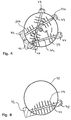
- FIG. 4 shows a section along the line IV-IV of FIG. 3.
- the first shafts 31a, 31b and 31c penetrate the drum 30 and are held in a stable position in bearings 42 to 47.
- the processing elements 35 can crush a bulk material or pile located in the drum 30.
- Machining elements 39 (not shown) are arranged on the second shaft 38 and can mix the bulk material located in the drum 30 when the second shaft 38 rotates in the direction of the arrow 48.
- the first shafts 31a, 31b, 31c have different positions to the second shaft 38.
- FIG. 5 shows a longitudinal section of a container which is only partially shown and which is designed as a drum 50.
- First shafts 51a and 51b penetrate the drum 50 and are held in a stable position on both sides in bearings 52a, 52b and opposite bearings, not shown.
- the processing elements 55 By rotating the first shafts 51a and 51b, the processing elements 55, which in turn are designed as knives and are firmly connected to the first shafts 51a, 51b, can comminute a bulk material or pile located in the drum 50.
- a second shaft 58 further processing elements 60 are fastened via arms 59 in order to mix bulk materials or piles located in the drum 50 and the processing elements when the second shaft 58 rotates about an axis of rotation 60 55 feed.
- a shaft 61 is mounted on one side on the drum 50, which is also provided with the processing elements 55.
- Fig. 6 shows a section of a container which is designed as a drum 70.
- a first shaft 71 penetrates the drum 70 and is held in a stable position in bearings 72 and 73.
- the processing elements 75 which are designed as successively spaced knives, can crush or chop a bulk material or pile located in the drum 70.
- the machining elements 75 connected to the first shaft 71 have a different radial extent.
- the ends of the processing elements 75 directed towards the peripheral surface of the drum 70 are adapted to the contour of the drum inner wall and are spaced therefrom. This creates a defined distance between the processing elements 75 and the peripheral surface of the drum 70, so that a bulk material or pile located in the drum 70 can be comminuted between the peripheral surface of the drum 70 and processing elements 75.
- the mixing elements shown in the figures are distributed over the circumference of the second shaft, so that axially directed conveying characteristics can be set for the material to be processed.
- a processing element 15 for solid materials, such as bulk goods and / or aggregates of any structure and consistency, is arranged in a container 10, which picks up or processes a material in batches or continuously, and in turn delivers it batchwise or continuously.
- the processing elements 15 are on a first shaft 11 stored.
- the first shaft 11 penetrates the container 10 completely and is supported on both sides (bearings 12, 13).
- a drive for the first shaft 11 is provided on one of the bearings 12, 13. Any machining tools, here machining elements 15, can be provided on the first shaft 11.
Landscapes
- Chemical & Material Sciences (AREA)
- Chemical Kinetics & Catalysis (AREA)
- Crushing And Pulverization Processes (AREA)
- Mixers Of The Rotary Stirring Type (AREA)
Abstract
Ein Bearbeitungselement von festen Materialien, wie Schüttgütern und/oder Haufwerken beliebiger Struktur und Konsistenz ist in einem Behälter (10) angeordnet, der das Material chargenweise oder kontinuierlich aufnimmt. Das oder die Bearbeitungselemente (15) sind auf oder an einer Welle (11) angeordnet, die den Behälter (10) in einer Querschnittsebene durchdringt. Der Behälter (10) weist eine in Stirnseiten des Behälters (10) gelagerte zweite Welle (26) auf, die mit als Mischkörper (28) ausgebildeten Bearbeitungselementen (28) versehen ist. Die Bearbeitungselemente (25) der ersten Welle (21) sind Materialaufschlußelemente. Am Behälter (10) sind zwei Lager (12, 13) vorgesehen, die die erste Welle (11) im Bereich der Enden lagestabil halten. Die Bearbeitungselemente (28) der zweiten Welle (26) rotieren zwischen den Bearbeitungselementen (25) der ersten Welle (31). Daher können bestehende Agglomeratbildungen eines Schüttguts aufgelöst und neue Agglomeratbildungen innerhalb des Behälters (10) Behälters beim Mischvorgang vermieden werden. Das Bearbeitungselement (15) kann ohne Beeinträchtigung auch unter größten Belastungen zur Bearbeitung fest zusammenhängender Materialien eingesetzt werden. <IMAGE>A processing element of solid materials, such as bulk goods and / or piles of any structure and consistency, is arranged in a container (10), which receives the material in batches or continuously. The processing element (s) (15) are arranged on or on a shaft (11) which penetrates the container (10) in a cross-sectional plane. The container (10) has a second shaft (26), which is mounted in the end faces of the container (10) and is provided with processing elements (28) designed as a mixing body (28). The processing elements (25) of the first shaft (21) are material disintegration elements. Two bearings (12, 13) are provided on the container (10) and hold the first shaft (11) in a stable position in the region of the ends. The machining elements (28) of the second shaft (26) rotate between the machining elements (25) of the first shaft (31). Existing agglomerate formations of a bulk material can therefore be dissolved and new agglomerate formations within the container (10) container avoided during the mixing process. The processing element (15) can be used without impairment even under the greatest loads for processing firmly connected materials. <IMAGE>
Description
Die Erfindung betrifft ein Bearbeitungselement von festen Materialien, wie Schüttgütern und/oder Haufwerken beliebiger Struktur und Konsistenz in einem Behälter, der das Material chargenweise oder kontinuierlich aufnimmt, wobei das oder die Bearbeitungselemente auf oder an einer Welle angeordnet sind, die den Behälter in einer Querschnittsebene durchdringt, und der Behälter eine in Stirnseiten des Behälters gelagerte zweite Welle aufweist, die mit als Mischkörper ausgebildeten Bearbeitungselementen versehen ist.The invention relates to a processing element of solid materials, such as bulk goods and / or piles of any structure and consistency in a container, which receives the material in batches or continuously, the processing element or elements being arranged on or on a shaft, which the container in a cross-sectional plane penetrates, and the container has a second shaft mounted in the end faces of the container, which is provided with processing elements designed as a mixing body.
Ein derartiges Bearbeitungselement ist durch die US 3,021,121 bekanntgeworden.Such a processing element has become known from US 3,021,121.
Eine erste Welle dieses Bearbeitungselements, das als Förderschnecke ausgebildet ist, durchdringt den Behälter quer zu einer zweiten Welle, die mit Mischkörpern versehen ist. Die beiden Wellen sind versetzt zu einander angeordnet, so daß die Bearbeitungselemente der beiden Wellen nicht direkt zusammenwirken. Durch die Förderschnecke wird bearbeitetes Schüttgut in vertikaler Richtung transportiert, so daß es bei Erreichen des oberen Endes der Förderschnecke wiederherunterfallen kann und einer erneuten Bearbeitung durch die Mischkörper zugeführt wird.A first shaft of this processing element, which is designed as a screw conveyor, penetrates the container transversely to a second shaft, which is provided with mixing bodies. The two shafts are staggered so that the machining elements of the two shafts do not interact directly. Machined bulk material is transported in the vertical direction by the screw conveyor, so that it can fall again when the upper end of the screw conveyor is reached and is reprocessed by the mixing bodies.
Durch die Förderschnecke wird nur eine geringe Durchmischung des Schüttguts durchgeführt, während die eigentliche durchmischende Bearbeitung des Schüttguts durch die an der zweiten Welle befestigten Mischkörper erfolgt. Eine Zerkleinerung oder ein Aufschließen von zusammenhängenden Agglomeraten des Schüttguts ist bei dem bekannten Bearbeitungselement nicht vorgesehen. Wenn daher feste Bestandteile innerhalb des Schüttguts vorhanden sind, kann keine bzw. nur eine sehr geringe Durchmischung des Schüttguts erreicht werden. Derartige Agglomeratbildungen können auch beim Mischung- bzw. Verdichtungsvorgang eines feuchten Schüttguts auftreten und folglich nicht mehr aufgelöst werden.Only a slight mixing of the bulk material is carried out by the screw conveyor, while the actual mixing processing of the bulk material is carried out by the mixing bodies attached to the second shaft. Comminution or disintegration of coherent agglomerates of the bulk material is not provided in the known processing element. If solid components are therefore present within the bulk material, no or very little mixing of the bulk material can be achieved. Such agglomerate formation can also occur during the mixing or compression process of a moist bulk material and consequently can no longer be dissolved.
Aus dem Prospekt "Industrielles Mischen im kontinuierlich arbeitenden Lödige-Mischer" von 5/1993 der Firma Lödige GmbH ist bekannt, eine an einer Seite eines Behälters gelagerte, in das Behälterinnere ragende Welle anzubringen, an der Bearbeitungselemente befestigt sind.From the brochure "Industrial Mixing in a Continuously Working Lödige Mixer" from 5/1993 of the company Lödige GmbH it is known to mount a shaft mounted on one side of a container and projecting into the interior of the container, to which processing elements are attached.
Die aus dem Prospekt bekannten Bearbeitungselemente werden zur Unterstützung eines Schleuderwerks (Welle + Mischelemente) bei vielen Mischprozessen eingesetzt. Bearbeitungselemente werden unter anderem zum Aufschließen von Verballungen, die produkt- , prozeßbedingt und/oder temporär sind, verwendet. Sie zerkleinern pasteuse Zusatzstoffe oder verhindern Agglomeratbildungen bei Befeuchtungsprozessen. Die Notwendigkeit des Bearbeitungselementeinsatzes ergibt sich bei den Befeuchtungsprozessen zur schnelleren Verteilung flüssiger oder pasteuser Komponenten und in der Beherrschung von Agglomerationstechniken und für Verdichtungsvorgänge.The processing elements known from the brochure are used to support a centrifugal unit (shaft + mixing elements) in many mixing processes. Processing elements are used, among other things, to unlock verbalizations that are product, process-related and / or temporary. They crush paste additives or prevent agglomerate formation during moistening processes. The need to use processing elements arises in the humidification processes for the faster distribution of liquid or paste-like components and in the mastery of agglomeration techniques and for compression processes.
Die bekannten Bearbeitungselemente gemäß dem vorgenannten Prospekt sind in einer kontinuierlich arbeitenden Maschine, die im wesentlichen aus einem horizontal gelagerten zylindrischen Behälter besteht, angebracht. In Abhängigkeit von der Froudezahl der Mischelementbewegung ändert sich das Bewegungsverhalten des Schüttguts im Mischraum. Bei zunächst langsam drehendem Schleuderwerk wird das Produkt in Drehrichtung angehoben, so daß sich ein Winkel der freien Produktoberfläche einstellt, der etwa dem Schüttgutwinkel des Produkts entspricht. Mit steigender Schleuderwerksdrehzahl werden vermehrt Teilchen aus dem Gutbett in den freien Mischraum geschleudert. Die Schüttung wird mehr und mehr fluidisiert. Im Bereich höherer Schleuderwerksdrehzahlen liegt im Mischraum ein mehr oder weniger geschlossener Produktring vor. Der Produktring entspricht in seiner Konsistenz einer sich verdichtenden Schüttung.The known processing elements according to the aforementioned brochure are installed in a continuously operating machine, which essentially consists of a horizontally mounted cylindrical container. The movement behavior of the bulk material in the mixing room changes depending on the Froude number of the mixing element movement. When the centrifugal unit rotates slowly at first, the product is raised in the direction of rotation, so that an angle of the free product surface is established which corresponds approximately to the bulk material angle of the product. With increasing spin speed, particles are thrown out of the material bed into the free mixing room. The bed is fluidized more and more. In the area of higher centrifugal machine speeds, there is a more or less closed product ring in the mixing room. The consistency of the product ring corresponds to a compacting fill.
Das bekannte Bearbeitungselement ist einseitig an einer Wand des Mischbehälters in den Mischbehälter hineinragend in einem Lager befestigt, das nach außen gerichtet eine Antriebseinheit (Motor) aufnimmt. Das Bearbeitungselement ragt in den Mischbehälter hinein und ist den Belastungen auftreffender Schüttgüter und/oder Haufwerke hinsichtlich seiner filigranen Anordnung ausgesetzt. Die Belastung der Bearbeitungselemente überträgt sich nachteiligerweise auch auf die Welle, an der das oder die Bearbeitungselemente befestigt sind, so daß die Welle nach einer starken Belastung entweder eine gewisse Verbiegung oder eine geringe seitliche Auslenkung erfahren kann. Dies ist deshalb möglich, weil die Mischelemente das zu bearbeitende Gut in den Bereich der Bearbeitungselemente fördern.The known processing element is fastened on one side to a wall of the mixing container projecting into the mixing container in a bearing which accommodates a drive unit (motor) directed outwards. The processing element protrudes into into the mixing container and is exposed to the loads of bulk goods and / or piles with regard to its filigree arrangement. The load on the machining elements is also disadvantageously transferred to the shaft to which the machining element or elements are fastened, so that the shaft can experience either a certain deflection or a slight lateral deflection after a heavy load. This is possible because the mixing elements convey the material to be processed into the area of the processing elements.
Ragt die einseitig gelagerte Welle weit in den Behälterinnenraum oder wird der Mischprozeß im mechanisch erzeugten Wirbelbett bzw. im Produktring ausgeführt oder sind die zu bearbeitenden Materialien großstückig bzw. sehr hart, so wird die Welle mit den Bearbeitungselementen sehr großen Belastungen ausgesetzt.If the shaft supported on one side extends far into the interior of the container or if the mixing process is carried out in the mechanically generated fluidized bed or in the product ring or if the materials to be machined are large or very hard, the shaft with the machining elements is exposed to very large loads.
Deshalb kann beispielsweise das bekannte Bearbeitungselement nicht zur Verkleinerung oder zum Aufschließen fest zusammenhängender Klumpen oder anderer fester Materialien, wie sie beispielsweise bei der Bodensanierung auftreten, eingesetzt werden. Wird das bekannte Bearbeitungselement trotzdem zu diesen Einsatzzwecken verwendet, so wird das Bearbeitungselement, die Welle und/oder das Lager der Welle derart belastet, daß die Gefahr einer Beschädigung der Welle mit den Bearbeitungselementen gegeben ist.For this reason, for example, the known processing element cannot be used for downsizing or disintegrating clumps or other solid materials, such as those that occur during soil remediation. If the known machining element is nevertheless used for these purposes, the machining element, the shaft and / or the bearing of the shaft are loaded in such a way that there is a risk of damage to the shaft with the machining elements.
Der vorliegenden Erfindung liegt daher die Aufgabe zugrunde, das bekannte Bearbeitungselement derart weiter zu entwickeln, daß bestehende Agglomeratbildungen eines Schüttguts aufgelöst und neue Agglomeratbildungen innerhalb eines Behälters beim Mischvorgang vermieden werden, und daß das Bearbeitungselement ohne Beeinträchtigung auch unter größten Belastungen zur Bearbeitung fest zusammenhängender Materialien einsetzbar ist.The present invention is therefore based on the object of further developing the known processing element in such a way that existing agglomerate formations of a bulk material are dissolved and new agglomerate formations within a container are avoided during the mixing process, and that the processing element can be used without impairment, even under the greatest loads, for processing firmly connected materials.
Die Aufgabe wird erfindungsgemäß dadurch gelöst, daß die Bearbeitungselemente der ersten Welle Materialaufschlußelemente sind, daß am Behälter zwei Lager vorgesehen sind, die die erste Welle im Bereich der Enden lagestabil halten, und daß die Bearbeitungselemente der zweiten Welle zwischen den Bearbeitungselementen der ersten Welle rotieren.The object is achieved in that the machining elements of the first shaft are material disintegration elements, that two bearings are provided on the container, which hold the first shaft in a stable position in the region of the ends, and that the machining elements of the second shaft rotate between the machining elements of the first shaft.
Die drehbare Welle, an der das erfindungsgemäße Bearbeitungselement befestigt werden kann, wird im allgemeinen zwischen den beiden Behälterwänden angeordnet und zweckmäßig so gestaltet, daß es ohne weiteres durch seine Lage gegen axiales Verschieben gesichert ist.The rotatable shaft, to which the machining element according to the invention can be attached, is generally arranged between the two container walls and expediently designed such that it is easily secured against axial displacement by its position.
Das erfindungsgemäße Bearbeitungselement hat den weiteren Vorteil, daß es auch bei der Bearbeitung bei der Bodensanierung anfallender Schüttgüter eingesetzt werden kann. Bei diesen Schüttgütern können sich zwischen den Bodenpartikeln harte Agglomerate verschiedenster Materialien befinden, die nach einer Bearbeitung getrennt werden sollen.The processing element according to the invention has the further advantage that it can also be used in the processing of bulk materials resulting from soil remediation. With these bulk materials, there may be hard agglomerates of various materials between the soil particles, which should be separated after processing.
Die Materialaufschlußelemente können Klingen, Messer usw. unterschiedlichster Art aufweisen. Dadurch können die erfindungsgemäßen Bearbeitungselemente vorteilhafterweise zur Zerkleinerung harter und festzusammenhängender Materialien oder Haufwerke eingesetzt werden. Durch die mögliche Kombination von Messerkopfformen und die richtige Materialwahl für die Bearbeitungselemente und die Welle kann die Zerkleinerung aufgrund der Messerkopfwirkung noch weiter gezielt verbessert werden. Weiterhin können die Bearbeitungselemente und/oder die Messerkopfformen aus Sonderwerkstoffen gefertigt oder mit diesen beschichtet sein.The material disintegration elements can have blades, knives, etc. of the most varied types. As a result, the machining elements according to the invention can advantageously be used for comminuting hard and firmly connected materials or piles. The possible combination of cutter head shapes and the right choice of material for the machining elements and the shaft mean that the size reduction can be further improved in a targeted manner due to the cutter head effect. Furthermore, the editing elements and / or the cutter head shapes are made of special materials or coated with them.
Es werden vorteilhafterweise zwei rotierende Wellen in einem Behälter miteinander in Kombination eingesetzt. Bearbeitungselemente der einen Welle können vorteilhafterweise zum Mischen dienen, während die Bearbeitungselemente der anderen Welle vorteilhafterweise zur Zerkleinerung bzw. zum Aufschließen fester Materialien dienen.Two rotating shafts in a container are advantageously used in combination with one another. Machining elements of one shaft can advantageously be used for mixing, while the machining elements of the other shaft advantageously serve for comminution or for disintegrating solid materials.
Die Stabilität und Präzision der erfindungsgemäßen Bearbeitungselemente wird noch weiter erhöht, wenn am Behälter Versteifungsringe für die Lager angebracht sind und die Lager im Bereich der Versteifungsringe angeordnet sind.The stability and precision of the machining elements according to the invention is further increased if stiffening rings for the bearings are attached to the container and the bearings are arranged in the region of the stiffening rings.
Bei einer besonders bevorzugten Ausführungsform der erfindungsgemäßen Bearbeitungselemente ist die erste Welle in dem Behälter horizontal oder in einer Zwischenstellung zwischen horizontal und vertikal ausgerichtet angeordnet.In a particularly preferred embodiment of the machining elements according to the invention, the first shaft is arranged horizontally in the container or in an intermediate position between horizontally and vertically aligned.
Die Lage der erfindungsgemäßen Bearbeitungselemente kann so auf einen von der Froudezahl abhängigen Schüttgutspiegel ausgerichtet werden. Über diese Maßnahme kann eine effektive Zerkleinerung oder Aufschließung des Schüttgutes und/oder des Haufwerkes erfolgen. Der Verkleinerungsprozeß im Behälter und damit die Zerkleinerungsgüte bzw. die Ausbeute lassen sich mit einer derartigen Anordnung der Bearbeitungselemente erheblich verbessern.The position of the processing elements according to the invention can thus be aligned with a bulk material level that is dependent on the Froude number. This measure can effectively comminute or disintegrate the bulk material and / or the pile. The shrinking process in the container and thus the shredding quality or the yield can be considerably improved with such an arrangement of the processing elements.
Bei einer weiteren Ausführungsform der vorliegenden Erfindung ist der Behälter als horizontal ausgerichtete Trommel ausgebildet, in der die Bearbeitungselemente der zweiten Welle über die Länge der Trommel gesehen zwischen den Bearbeitungselementen der ersten Welle rotieren.In a further embodiment of the present invention, the container is designed as a horizontally aligned drum, in which the machining elements of the second shaft, viewed over the length of the drum, between the machining elements the first shaft rotate.
Die in Stirnseiten der Trommel gelagerte zweite Welle wird vorzugsweise Pflugscharschaufeln als Bearbeitungselement aufweisen, die zum Mischen von Materialien dienen.The second shaft mounted in the end faces of the drum will preferably have ploughshare blades as the processing element, which are used to mix materials.
Wenn die Drehzahl der Bearbeitungselemente
der ersten Welle größer ist als die Drehzahl der Bearbeitungselemente, die auf der zweiten Welle vorgesehen sind, können die Bearbeitungselemente der ersten Welle als Zerkleinerer oder Zerhacker eingesetzt werden.If the speed of the machining elements
of the first shaft is greater than the speed of the machining elements provided on the second shaft, the machining elements of the first shaft can be used as a shredder or chopper.
Vorteilhafterweise weisen die Bearbeitungselemente auf der zweiten Welle einen Mischkörper auf, der im Bereich der Trommel nahe der Innenwandung vorgesehen ist und der über einen Arm mit der zweiten Welle verbunden ist.The processing elements on the second shaft advantageously have a mixing body which is provided in the region of the drum near the inner wall and which is connected to the second shaft by an arm.
Bei einer weiteren Ausführungsform der vorliegenden Erfindung sind die Bearbeitungselemente der ersten Welle in einem Bereich auf der ersten Welle angeordnet, welcher beabstandet neben den Armen liegt.In a further embodiment of the present invention, the machining elements of the first shaft are arranged in an area on the first shaft which is spaced apart from the arms.
Dies hat den weiteren Vorteil, daß die Kombination von Mischen und Zerkleinern in unterschiedlichsten Bereichen des Behälters oder der horizontalen Trommel möglich ist.This has the further advantage that the combination of mixing and crushing in different areas of the container or the horizontal drum is possible.
Bei einer anderen Ausführungsform der vorliegenden Erfindung sind die Bearbeitungselemente der ersten Welle im Bereich der Mischkörper angeordnet.In another embodiment of the present invention, the machining elements of the first shaft are arranged in the area of the mixing body.
Vorteilhafterweise können die Bearbeitungselemente der zweiten Welle, die als Pflugscharschaufeln ausgebildet sind, den Bearbeitungselementen der ersten Welle das Material zum Zerkleinern direkt zuführen. Auf diese Art und Weise wird die Kombination von Mischen und Zerkleinern noch weiter verbessert.Advantageously, the processing elements of the second shaft, which are designed as ploughshare blades, the processing elements of the first shaft, the material for crushing feed directly. In this way, the combination of mixing and crushing is further improved.
Es versteht sich, daß auch andere Formen als Pflugscharschaufeln für die hier angesprochenen Bearbeitungsprozesse eingesetzt werden können (Stollenschaufeln, Beckerschaufeln usw). Ebenfalls können mehrere erste Wellen im gleichen oder zueinander unterschiedlichen Lagepositionen in dem Behälter oder in der Trommel angeordnet sein. Ebenfalls lassen sich zweiseitig gelagerte Wellen mit einseitig gelagerten Wellen längs des Behälters kombinieren, wobei die Wellen mit unterschiedlichsten Bearbeitungselementen bestückt sein können. Die Wellen werden über elektrische Motoren angetrieben. Bei Bedarf kann zwischen den Wellen und den Motoren auch noch ein Getriebe vorgesehen sein.It goes without saying that shapes other than ploughshare blades can also be used for the machining processes mentioned here (cleat blades, bucket blades, etc.). Likewise, several first shafts can be arranged in the same or different position positions in the container or in the drum. Two-sided shafts can also be combined with single-sided shafts along the container, and the shafts can be equipped with a wide variety of processing elements. The shafts are driven by electric motors. If necessary, a transmission can also be provided between the shafts and the motors.
Weitere Vorteile ergeben sich aus der Beschreibung der beigefügten Zeichnung. Ebenso können die vorstehend genannten und die noch weiter aufgeführten Merkmale erfindungsgemäß jeweils einzeln oder in beliebigen Kombinationen miteinander verwendet werden. Die erwähnten Ausführungsformen sind nicht als abschließende Aufzählung zu verstehen, sondern haben vielmehr beispielhaften Charakter.Further advantages result from the description of the attached drawing. Likewise, the features mentioned above and those listed further can be used according to the invention individually or in any combination with one another. The mentioned embodiments are not to be understood as an exhaustive list, but rather have an exemplary character.
Die Erfindung ist in der Zeichnung dargestellt und wird anhand von Ausführungsbeispielen näher erläutert. Es zeigt:
- Fig. 1
- einen Querschnitt eines Behälters mit an einer ersten Welle angeordneten Bearbeitungselementen;
- Fig. 2
- einen Querschnitt eines Behälters mit an einer ersten Welle angeordneten Bearbeitungselementen und an einer zweiten Welle angeordneten weiteren Bearbeitungselementen;
- Fig. 3
- eine Gesamtansicht eines Behälters;
- Fig. 4
- einen Schnitt längs einer Linie IV-IV durch den Behälter nach Fig. 3;
- Fig. 5
- einen Längsschnitt durch einen weiteren Behälter mit an einer ersten Welle angeordneten Bearbeitungselementen und an einer zweiten Welle angeordneten weiteren Bearbeitungselementen, und
- Fig. 6
- einen Querschnitt durch einen weiteren Behälter mit an einem an einer ersten Welle angeordneten Bearbeitungselementen.
- Fig. 1
- a cross section of a container with processing elements arranged on a first shaft;
- Fig. 2
- a cross section of a container with arranged on a first shaft processing elements and on a second shaft arranged further processing elements;
- Fig. 3
- an overall view of a container;
- Fig. 4
- a section along a line IV-IV through the container of FIG. 3;
- Fig. 5
- a longitudinal section through a further container with processing elements arranged on a first shaft and further processing elements arranged on a second shaft, and
- Fig. 6
- a cross section through a further container with arranged on a first shaft processing elements.
Die in den Figuren gezeigten Darstellungen zeigen den erfindungsgemäßen Gegenstand stark schematisiert und die einzelnen Zuordnungen sind nicht maßstäblich zu verstehen.The representations shown in the figures show the subject according to the invention in a highly schematic manner and the individual assignments are not to be understood to scale.
Fig.1 zeigt einen Querschnitt eines Behälters, der als horizontal ausgerichtete Trommel 10 ausgebildet ist. Eine erste Welle 11 durchdringt die Trommel 10 und ist in Lagern 12 und 13 lagestabil gehalten. Das Lager 12 kann einen Antrieb für die Welle 11 aufnehmen (nicht gezeigt). Die drehbare erste Welle 11 ist zwischen den Wänden der Trommel 10 angeordnet und zweckmäßig so gestaltet, daß die erste Welle 11 ohne weiteres durch ihre Lage gegen axiales Verschieben gesichert ist. Durch eine Rotation der ersten Welle 11 in Pfeilrichtung 14 können die Bearbeitungselemente 15, die als hintereinander gereihte Messer ausgebildet und mit der ersten Welle 11 fest verbunden sind, ein in der Trommel 10 befindliches Schüttgut oder Haufwerk zerkleinern, verdichten oder zerhacken. Die Bearbeitungselemente 15 könnten aber auch in anderer Art und Weise ausgebildet sein, um ein Schüttgut oder ein Haufwerk zu bearbeiten. Fig. 1 shows a cross section of a container which is designed as a horizontally aligned
Fig. 2 zeigt einen Querschnitt eines Behälters, der als Trommel 20 ausgebildet ist. Eine erste Welle 21 durchdringt die Trommel 20 und ist in Lagern 22 und 23 lagestabil gehalten. Durch eine Rotation der ersten Welle 21 in Pfeilrichtung 24 können die Bearbeitungselemente 25, die als Messer ausgebildet und mit der ersten Welle 21 fest verbunden sind, ein in der Trommel 20 befindliches Schüttgut oder Haufwerk zerkleinern oder zerhacken. An einer zweiten Welle 26, die in Stirnseiten der Trommel 20 gelagert ist, ist über einen Arm 27 ein weiteres Bearbeitungselement 28 befestigt. Das Bearbeitungselement 28 ist vorzugsweise als Pflugscharschaufel ausgebildet, um das in der Trommel 20 befindliche Schüttgut oder Haufwerk zu durchmischen. Durch eine Drehung der zweiten Welle 26 in Pfeilrichtung 29 wird das Schüttgut zum einen durchmischt und zum anderen den Messern 25 zum Zerkleinern bzw. Verdichten zugeführt. Die Messer 25 an der schräg angeordneten ersten Welle 21 reichen unterschiedlich weit in das Schüttgut hinein. Die erste Welle 21 ist oberhalb der zweiten Welle 26 angeordnet. Sie kann in anderen Ausführungsformen auch unterhalb der zweiten Welle 26 verlaufen. Fig. 2 shows a cross section of a container which is designed as a
Fig. 3 zeigt eine Seitenansicht eines Behälters, der als Trommel 30 ausgebildet ist. Erste Wellen 31a, 31b und 31c durchdringen die Trommel 30 und sind in Lagern lagestabil gehalten. Durch eine Rotation der ersten Wellen 31a, 31b und 31c können die Bearbeitungselemente 35, die als Messer unterschiedlichster Art ausgebildet und mit den ersten Wellen fest verbunden sind, ein in der Trommel 30 befindliches Schüttgut oder Haufwerk zerkleinern, verdichten oder zerhacken. An Stirnseiten 36, 37 der Trommel 30 ist eine zweite Welle 38 gelagert, die mit weiteren Bearbeitungselementen 39 versehen ist. Die Bearbeitungselemente 39 sind wiederum als Pflugscharschaufeln ausgebildet, um ein in der Trommel 30 befindliches Schüttgut zu durchmischen. Fig. 3 shows a side view of a container which is designed as a drum 30.
Fig. 4 zeigt einen Schnitt längs der Linie IV-IV der Fig. 3. Die ersten Wellen 31a, 31b und 31c durchdringen die Trommel 30 und sind in Lagern 42 bis 47 lagestabil gehalten. Durch eine Rotation der ersten Wellen 31a, 31b und 31c können die Bearbeitungselemente 35 ein in der Trommel 30 befindliches Schüttgut oder Haufwerk zerkleinern. An der zweiten Welle 38 sind nicht gezeigte Bearbeitungselemente 39 angeordnet, die bei einer Rotation der zweiten Welle 38 in Pfeilrichtung 48 das in der Trommel 30 befindliche Schüttgut durchmischen können. Die ersten Wellen 31a, 31b, 31c weisen unterschiedliche Lagen zur zweiten Welle 38 auf. FIG. 4 shows a section along the line IV-IV of FIG. 3. The
Fig. 5 zeigt einen Längsschnitt eines nur teilweise gezeigten Behälters, der als Trommel 50 ausgebildet ist. Erste Wellen 51a und 51b durchdringen die Trommel 50 und sind in Lagern 52a, 52b und nicht gezeigten gegenüberliegenden Lagern beidseitig lagestabil gehalten. Durch eine Rotation der ersten Wellen 51a und 51b können die Bearbeitungselemente 55, die wiederum als Messer ausgebildet und mit den ersten Wellen 51a, 51b fest verbunden sind, ein in der Trommel 50 befindliches Schüttgut oder Haufwerk zerkleinern. An einer zweiten Welle 58 sind über Arme 59 weitere Bearbeitungselemente 60 befestigt, um bei einer Rotation der zweiten Welle 58 um eine Rotationsachse 60, in der Trommel 50 befindliche Schüttgüter oder Haufwerke zu durchmischen und den Bearbeitungselementen 55 zuzuführen. Außerdem ist an der Trommel 50 eine einseitig gelagerte Welle 61 befestigt, die ebenfalls mit den Bearbeitungselementen 55 versehen ist. 5 shows a longitudinal section of a container which is only partially shown and which is designed as a
Fig. 6 zeigt einen Schnitt eines Behälters, der als Trommel 70 ausgebildet ist. Eine erste Welle 71 durchdringt die Trommel 70 und ist in Lagern 72 und 73 lagestabil gehalten. Durch eine Rotation der ersten Welle 71 können die Bearbeitungselemente 75, die als hintereinander liegende zueinander abgestufte Messer ausgebildet sind, ein in der Trommel 70 befindliches Schüttgut oder Haufwerk zerkleinern oder zerhacken. Die mit der ersten Welle 71 verbundenen Bearbeitungselemente 75 weisen eine unterschiedliche radiale Erstreckung auf. Die zur Umfangsfläche der Trommel 70 gerichteten Enden der Bearbeitungselemente 75 sind der Kontur der Trommelinnenwandung angepaßt und davon beabstandet. Dadurch entsteht ein definierter Abstand zwischen Bearbeitungselementen 75 und der Umfangsfläche der Trommel 70, so daß ein in der Trommel 70 befindliches Schüttgut oder Haufwerk gezielt zwischen Umfangsfläche der Trommel 70 und Bearbeitungselementen 75 zerkleinert werden kann. Fig. 6 shows a section of a container which is designed as a
Die in den Figuren gezeigten Mischelemente sind über den Umfang der zweiten Welle verteilt, so daß axial gerichtete Fördercharakteristiken für das zu bearbeitende Gut eingestellt werden können.The mixing elements shown in the figures are distributed over the circumference of the second shaft, so that axially directed conveying characteristics can be set for the material to be processed.
Ein Bearbeitungselement 15 für feste Materialien, wie Schüttgütern und/oder Haufwerken beliebiger Struktur und Konsistenz ist in einem Behälter 10 angeordnet, der ein Material chargenweise oder kontinuierlich aufnimmt, bearbeitet, und wiederum chargenweise bzw. kontinuierlich abgibt. Die Bearbeitungselemente 15 sind auf einer ersten Welle 11 gelagert. Die erste Welle 11 durchdringt den Behälter 10 vollkommen und ist beiseitig gelagert (Lager 12, 13). An einem der Lager 12, 13 ist ein Antrieb für die erste Welle 11 vorgesehen. Auf der ersten Welle 11 können beliebige Bearbeitungswerkzeuge, hier Bearbeitungselemente 15, vorgesehen sein.A
Claims (10)
dadurch gekennzeichnet,
daß die Bearbeitungselemente (25; 35; 55) der ersten Welle (21; 31a, 31b, 31c; 51a, 51b) Materialaufschlußelemente sind, daß am Behälter (10; 20; 30; 50; 70) zwei Lager (12, 13; 22, 23; 42, 43, 44, 45, 46, 47; 52a, 52b; 72, 73) vorgesehen sind, die die erste Welle (11; 21; 31a, 31b, 31c; 51a, 51b; 71) im Bereich der Enden lagestabil halten, und daß die Bearbeitungselemente (28; 39; 60) der zweiten Welle (26; 38; 58) zwischen den Bearbeitungselementen (25; 35; 55) der ersten Welle (31a, 31b, 31c; 51a, 51b) rotieren.Processing element of solid materials, such as bulk goods and / or aggregates of any structure and consistency in a container (10; 20; 30; 50; 70), which receives the material in batches or continuously, the processing element or elements (15; 35; 55) are arranged on or on a shaft (11; 21; 31a, 31b, 31c; 51a, 51b; 71) which penetrates the container (10; 20; 30; 50; 70) in a cross-sectional plane, and the container (10; 20; 30; 50; 70) has a second shaft (26; 38; 58) mounted in the end faces of the container (10; 20; 30; 50; 70), which is equipped with processing elements (28; 39; 60) is provided,
characterized,
that the processing elements (25; 35; 55) of the first shaft (21; 31a, 31b, 31c; 51a, 51b) are material disintegration elements, that on the container (10; 20; 30; 50; 70) two bearings (12, 13; 22, 23; 42, 43, 44, 45, 46, 47; 52a, 52b; 72, 73) are provided, which cover the first shaft (11; 21; 31a, 31b, 31c; 51a, 51b; 71) hold the ends in a stable position and that the machining elements (28; 39; 60) of the second shaft (26; 38; 58) between the machining elements (25; 35; 55) of the first shaft (31a, 31b, 31c; 51a, 51b) rotate.
Applications Claiming Priority (2)
| Application Number | Priority Date | Filing Date | Title |
|---|---|---|---|
| DE4440873 | 1994-11-16 | ||
| DE4440873A DE4440873A1 (en) | 1994-11-16 | 1994-11-16 | Materials processing assembly |
Publications (1)
| Publication Number | Publication Date |
|---|---|
| EP0722770A1 true EP0722770A1 (en) | 1996-07-24 |
Family
ID=6533433
Family Applications (1)
| Application Number | Title | Priority Date | Filing Date |
|---|---|---|---|
| EP95117760A Withdrawn EP0722770A1 (en) | 1994-11-16 | 1995-11-11 | Processing element for solid substances |
Country Status (2)
| Country | Link |
|---|---|
| EP (1) | EP0722770A1 (en) |
| DE (1) | DE4440873A1 (en) |
Cited By (1)
| Publication number | Priority date | Publication date | Assignee | Title |
|---|---|---|---|---|
| EP2578306A1 (en) | 2011-10-05 | 2013-04-10 | Gebr. Lödige Maschinenbau-Gesellschaft mit beschränkter Haftung | Mixer with grinding and dispersion device |
Families Citing this family (1)
| Publication number | Priority date | Publication date | Assignee | Title |
|---|---|---|---|---|
| DE102007009377B4 (en) | 2007-02-21 | 2009-01-02 | Stiftung Alfred-Wegener-Institut für Polar- und Meeresforschung Stiftung des öffentlichen Rechts | Ozone probe with hydrothermal buffer |
Citations (6)
| Publication number | Priority date | Publication date | Assignee | Title |
|---|---|---|---|---|
| US3021121A (en) | 1960-09-16 | 1962-02-13 | Seco Inc | Feed mixer |
| CH367379A (en) * | 1957-12-20 | 1963-02-15 | Loedige Wilhelm | Method and device for mixing and comminuting powdery, fine-grained and fibrous mixed goods |
| DE1432028A1 (en) * | 1964-02-18 | 1968-10-31 | Draiswerke Gmbh | Method for operating mixing machines and the associated mixing machine |
| GB1149850A (en) * | 1965-12-17 | 1969-04-23 | Draiswerke Gmbh | Improvements relating to mixing apparatus for fibrous materials |
| WO1993002984A1 (en) * | 1991-07-27 | 1993-02-18 | Babcock-Bsh Aktiengesellschaft | Use of mixing, granulating and drying device |
| WO1994012271A1 (en) * | 1992-12-02 | 1994-06-09 | Conversion Systems, Inc. | An improved pug mill mixer |
Family Cites Families (3)
| Publication number | Priority date | Publication date | Assignee | Title |
|---|---|---|---|---|
| US1340787A (en) * | 1920-01-30 | 1920-05-18 | Harry J Morley | Rivet-head catcher |
| GB647112A (en) * | 1948-06-07 | 1950-12-06 | Foster Yates & Thom Ltd | Improvements relating to powder mixing machines |
| DE3711987A1 (en) * | 1987-04-09 | 1988-10-27 | Durmersheim Baustoffwerke | Mixing and distribution apparatus for mixtures of pulverulent to granular solids |
-
1994
- 1994-11-16 DE DE4440873A patent/DE4440873A1/en not_active Withdrawn
-
1995
- 1995-11-11 EP EP95117760A patent/EP0722770A1/en not_active Withdrawn
Patent Citations (6)
| Publication number | Priority date | Publication date | Assignee | Title |
|---|---|---|---|---|
| CH367379A (en) * | 1957-12-20 | 1963-02-15 | Loedige Wilhelm | Method and device for mixing and comminuting powdery, fine-grained and fibrous mixed goods |
| US3021121A (en) | 1960-09-16 | 1962-02-13 | Seco Inc | Feed mixer |
| DE1432028A1 (en) * | 1964-02-18 | 1968-10-31 | Draiswerke Gmbh | Method for operating mixing machines and the associated mixing machine |
| GB1149850A (en) * | 1965-12-17 | 1969-04-23 | Draiswerke Gmbh | Improvements relating to mixing apparatus for fibrous materials |
| WO1993002984A1 (en) * | 1991-07-27 | 1993-02-18 | Babcock-Bsh Aktiengesellschaft | Use of mixing, granulating and drying device |
| WO1994012271A1 (en) * | 1992-12-02 | 1994-06-09 | Conversion Systems, Inc. | An improved pug mill mixer |
Cited By (2)
| Publication number | Priority date | Publication date | Assignee | Title |
|---|---|---|---|---|
| EP2578306A1 (en) | 2011-10-05 | 2013-04-10 | Gebr. Lödige Maschinenbau-Gesellschaft mit beschränkter Haftung | Mixer with grinding and dispersion device |
| DE102011084053A1 (en) | 2011-10-05 | 2013-04-11 | Gebr. Lödige Maschinenbau-GmbH | Mixer with crushing and dispersing device |
Also Published As
| Publication number | Publication date |
|---|---|
| DE4440873A1 (en) | 1996-05-30 |
Similar Documents
| Publication | Publication Date | Title |
|---|---|---|
| DE4341606C2 (en) | Method and device for cutting lumpy edible products | |
| EP0565887A1 (en) | Apparatus for working of chocolate masses and its use for making crumbs | |
| DE3807983C2 (en) | Crushing device | |
| EP0377161A1 (en) | Method and device for reprocessing waste dough into new dough | |
| DE3515318A1 (en) | PIN MILL FOR MIXERS | |
| DE1782585A1 (en) | Mixer | |
| EP0722770A1 (en) | Processing element for solid substances | |
| WO2020200759A1 (en) | Laboratory cutting mill for cutting comminution of specimens | |
| EP0474102B1 (en) | Method and device for grinding and intensive mixing bulk material and/or liquids with different pouring capability, density or viscosity for obtaining homogeneous mixtures | |
| DE8331826U1 (en) | Shredding and mixing machine for biological and organic shredded material | |
| DE2309257A1 (en) | PELLETIZING DEVICE WITH SCREW CONVEYOR | |
| DE2519848C2 (en) | Hand mill for making flours from vegetable products | |
| DE844116C (en) | Shredding machine for the treatment of cellulose and / or waste paper | |
| DE3406285C2 (en) | ||
| DE19623217A1 (en) | Digestion tool | |
| DE3416009A1 (en) | Machine for the comminution of maize, CCM or moist grain and process for the use of the machine | |
| EP0801975A1 (en) | Apparatus for treating organic waste | |
| DE3202308C2 (en) | ||
| DE19949165A1 (en) | Mixer, for soil treatment machine e.g. for treating excavated soil at a building site, has number of rotary impact elements adapted to the machine size | |
| DE102014005328A1 (en) | Apparatus for comminuting lumpy residues of palm oil production | |
| DE19652323A1 (en) | Cutting set for a screw conveyor | |
| DE19846372B4 (en) | Hopper chopper for crushing fractions, especially made of wood | |
| DE968672C (en) | Device for the comminution of, in particular, vegetable matter using the hammer mill principle | |
| DE2739106C2 (en) | Apparatus for stirring a liquid containing solid particles | |
| DE3123484C2 (en) | Shredding device for fibrous material |
Legal Events
| Date | Code | Title | Description |
|---|---|---|---|
| PUAI | Public reference made under article 153(3) epc to a published international application that has entered the european phase |
Free format text: ORIGINAL CODE: 0009012 |
|
| AK | Designated contracting states |
Kind code of ref document: A1 Designated state(s): CH DE ES FR GB IT LI |
|
| 17P | Request for examination filed |
Effective date: 19960711 |
|
| 17Q | First examination report despatched |
Effective date: 19971229 |
|
| STAA | Information on the status of an ep patent application or granted ep patent |
Free format text: STATUS: THE APPLICATION IS DEEMED TO BE WITHDRAWN |
|
| 18D | Application deemed to be withdrawn |
Effective date: 20010601 |