EP0722233A2 - Synchronisierung in einem Datenkommunikationsnetzwerk - Google Patents
Synchronisierung in einem Datenkommunikationsnetzwerk Download PDFInfo
- Publication number
- EP0722233A2 EP0722233A2 EP95309322A EP95309322A EP0722233A2 EP 0722233 A2 EP0722233 A2 EP 0722233A2 EP 95309322 A EP95309322 A EP 95309322A EP 95309322 A EP95309322 A EP 95309322A EP 0722233 A2 EP0722233 A2 EP 0722233A2
- Authority
- EP
- European Patent Office
- Prior art keywords
- transfer
- time
- node
- transfer device
- timing
- Prior art date
- Legal status (The legal status is an assumption and is not a legal conclusion. Google has not performed a legal analysis and makes no representation as to the accuracy of the status listed.)
- Granted
Links
Images






Classifications
-
- H—ELECTRICITY
- H04—ELECTRIC COMMUNICATION TECHNIQUE
- H04J—MULTIPLEX COMMUNICATION
- H04J3/00—Time-division multiplex systems
- H04J3/02—Details
- H04J3/06—Synchronising arrangements
- H04J3/0635—Clock or time synchronisation in a network
- H04J3/0638—Clock or time synchronisation among nodes; Internode synchronisation
- H04J3/0658—Clock or time synchronisation among packet nodes
- H04J3/0661—Clock or time synchronisation among packet nodes using timestamps
- H04J3/0667—Bidirectional timestamps, e.g. NTP or PTP for compensation of clock drift and for compensation of propagation delays
-
- G—PHYSICS
- G06—COMPUTING OR CALCULATING; COUNTING
- G06F—ELECTRIC DIGITAL DATA PROCESSING
- G06F1/00—Details not covered by groups G06F3/00 - G06F13/00 and G06F21/00
- G06F1/04—Generating or distributing clock signals or signals derived directly therefrom
- G06F1/14—Time supervision arrangements, e.g. real time clock
-
- H—ELECTRICITY
- H04—ELECTRIC COMMUNICATION TECHNIQUE
- H04J—MULTIPLEX COMMUNICATION
- H04J3/00—Time-division multiplex systems
- H04J3/02—Details
- H04J3/06—Synchronising arrangements
- H04J3/0635—Clock or time synchronisation in a network
- H04J3/0638—Clock or time synchronisation among nodes; Internode synchronisation
- H04J3/0658—Clock or time synchronisation among packet nodes
- H04J3/0673—Clock or time synchronisation among packet nodes using intermediate nodes, e.g. modification of a received timestamp before further transmission to the next packet node, e.g. including internal delay time or residence time into the packet
-
- H—ELECTRICITY
- H04—ELECTRIC COMMUNICATION TECHNIQUE
- H04J—MULTIPLEX COMMUNICATION
- H04J3/00—Time-division multiplex systems
- H04J3/02—Details
- H04J3/06—Synchronising arrangements
- H04J3/0635—Clock or time synchronisation in a network
- H04J3/0685—Clock or time synchronisation in a node; Intranode synchronisation
- H04J3/0697—Synchronisation in a packet node
Definitions
- This invention relates to a data communication network and to a network transfer device for use in, for example, loosely coupled distributed systems for serial communication and a number of nodes.
- Each node contains an event recognizer and often a local real-time clock.
- each node contains a local clock.
- the first is syntonization, that is ensuring the local clocks at each node are running at the same rate.
- the second is synchronization, that is ensuring the local clocks report the same value of time at a given instant.
- the causes for inaccuracy and degradation in synchronization are the failure to maintain syntonization and inaccuracies in the setting or resetting of the local times values of the clocks.
- the local clocks lose syntonization because there are differences and drifts in the fundamental frequency of the oscillators which drive the clocks.
- each local clock recognizes the local time of certain events and the nodes exchange messages to report these times.
- a preferred communication protocol between the nodes is a packet based serial protocol, such as Ethernet, token rings such as IEEE 802.5 or LonTalk (TM Echelon).
- the protocol is implemented by a protocol stack and the operating system of the node.
- the accuracy to which the clocks can be synchronized by exchanging messages currently is limited by the time jitter introduced by the protocol stack and operating system of each node.
- An additional problem is the latency or propagation delay of a message between nodes.
- jitter and delay can be introduced by other network elements such as gateways, bridges, and routers, or the physical communication medium.
- One method to manage time jitter and latency between the nodes is to use dedicated, calibrated trigger lines between the various nodes to synchronize the clocks, measurements, or the application of control.
- the dedicated calibrated trigger lines can be very accurate, systems quickly become unmanageable and expensive as the number of nodes increases.
- the desired events may be controlled by issuing commands to the nodes from a central controller over a control bus, such as IEEE488, or serial protocols, such as Ethernet.
- a control bus such as IEEE488, or serial protocols, such as Ethernet.
- Another method is to add a dedicated synchronization unit with a dedicated time output within each node.
- Each synchronization unit is connected to the local clock.
- Each local clock communicates with every node in the distributed network via the communication unit of the node to supply a global synchronized time signal.
- a message containing the local time of the sender is broadcast on the network by the synchronization unit.
- the receiving node calculates a correction factor to be applied to the local clock.
- This system is illustrated in Figure 1. However, as shown in Figure 1, this technique may remove the effects of the operating system but does not remove the jitter and latency of the protocol stack of the communication system.
- synchronization unit in a microprocessor may introduce jitter of its own due to operating system or interrupt behavior of the microprocessor. This system also introduces an unknown latency within the synchronization unit itself. As described by Kopetz, the synchronization unit must process all received messages which makes the jitter problem even harder to manage.
- each node contains a time generator, a time bus, and two snapshot registers.
- the local time of day is continuously output on the time bus.
- This method may remove operating system jitter and delay but does not solve the protocol stack jitter and delay problem.
- the local time at which the sending node submits a message to the communication module of the sending node is known, the receiving nodes do not know when a message was actually transmitted because the communications path between the node and the timing bus may have different propagation delays and the jitter in the protocol stacks of the participating nodes.
- the synchronous unit processes all received messages which increases the difficulty in managing the jitter problem.
- the present invention seeks to provide improved data communication.
- the preferred embodiments can provide a system in which each node in a distributed system maintained syntonization and synchronization of its local clock in an efficient and economical manner that minimized the temporal jitter and latency in the communication system. It is also possible to syntonize and synchronize throughout the overall system.
- the invention can provide a method for compensating for the time delay and jitter of messages transmitted between the nodes by using the event recognizer.
- the preferred embodiment provides a method for syntonizing and synchronizing the local clocks in a loosely distributed network using messages carried by the communication media.
- the accuracy is improved by eliminating operating system and protocol stack delays using a "time packet detector".
- Each node contains a time packet detector (TPD) which recognizes signatures of specially designated timing packets in a jitter-free fashion.
- TPD time packet detector
- a node may receive a variety of message packets such as data, control, etc.
- the TPD solely detects the passage of the timing packets.
- the TPD observes the packet data stream as close to the communication media as possible to minimize delay and jitter that results from the local protocol stack and operation system.
- the TPD When a timing packet is detected by the TPD, the TPD generates a trigger signal, which may be used to capture the time from the local clock.
- the captured time is the local time at which the timing packet was received or transmitted by the node.
- Timing packets are treated as events that are time stamped with the current local time at each node and these timestamps are then reported to the other nodes. These timestamps form the basis for the correction factors applied to each local clock. These factors may include corrections for latency between nodes. The remaining jitter is due only to the communication medium itself and the communication access mechanism between the time recording point and the communication medium.
- a first node sends a first timing packet that is recognized and detected by its TPD.
- This TPD generates a transmitting timestamp that reflects the local time of transmission, as measured by the transmitting clock.
- the first timing packet may contain an identifier for unique identification. The transmission time and identifier of the first timing packet are subsequently transmitted by the transmitting node in a first synchronization message.
- a second node receives the first timing packet and the first synchronization message from the first node.
- the TPD of the receiving node detects the arrival of the first timing packet and generates a reception timestamp that reflects the local time of reception, as measured by the receiving clock.
- the receiving node next receives the first synchronization message and compares the transmitting timestamp with the reception timestamp.
- the apparent difference and drift between the first and the second clocks can be computed and used with a suitable algorithm to synchronize and syntonize the clocks.
- the latency of the transmission of the timing packet may be measured by repeating the above sequence bidirectionally. Synchronization accuracy is improved by taking account of this latency measurement.
- Any node in a loosely distributed network can initiate a clock synchronization or syntonization process.
- Each of the nodes contains a time packet detector (TPD), a time service block (TSB), and a local media access block (LMA).
- TPD time packet detector
- TTB time service block
- LMA local media access block
- the TPD and TSB in concert, recognize the local time of transmission or receipt of timing packets as opposed to the time of scheduling or acknowledgment of the timing packet.
- the TPD detects timing packets that enter or leave the nodes.
- Timing packets are a specific packet type designated within the class of messages used in the communication protocol. The detected timing packets can be used by a receiving node for synchronization or event execution.
- a node When a node initiates synchronization, it transmits a first timing packet followed by a synchronization message that contains the local transmittal time of the first timing packet.
- the receiving node (the node to be synchronized) compares the local transmittal time contained in the synchronization message with its local receipt time for the first timing packet. A sequence of such results may be used to synchronize or syntonize the clocks in the distributed network.
- FIG. 3 illustrates a network of nodes where timing of events is important.
- a first node 2 is connected to a second node 2' through a communication medium 4.
- An optional third node 2'' is connected to the communication medium 4.
- Each node can both initiate and respond to timing packets and synchronization messages in the network.
- each node contains a time packet detector (TPD).
- TPD time packet detector
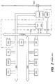
- FIG 4 illustrates a functional block diagram for node 2 shown in Figure 3.
- a time packet detector (TPD) 6 is connected to a local media access block (LMA) 8 and a time service block (TSB) 10.
- the LMA 8 is connected to the TSB 10 and the communication medium 4.
- the TSB 10 and the LMA 8 are each connected to a basic node function block 12.
- the basic node function block 12 represents an application function that makes use of the timing service provided herein.
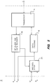
- FIG 5 illustrates a functional block diagram for the local media access block (LMA) 8 shown in Figure 4.
- a transceiver 14 is connected to the communication medium 4, a bit-clock and data recovery block 16, and a data encoding block 18.
- the bit-clock and data recovery block 16 is connected to the transceiver 14, a protocol stack 20, and the TPD 6.
- the data encoding block 18 is further connected to the protocol stack 20 and the transceiver 14.
- the TPD 6 is connected to the data encoding block 18.
- the protocol stack 20 is connected to the TSB 10 and the basic node function block 12.
- the bit-clock and data recovery block 16 and the protocol stack 20 are further connected to the TPD 6.
- the transceiver 14 provides physical access to the communication media 4.
- the bit-clock and data recovery block 16 receives raw signals from the transceiver 14 and recovers a bit-clock signal and a data bit stream which is synchronous with an incoming data bit stream.
- the jitter of this recovery process will typically be the dominant remaining source of jitter in the system.
- the data encoding block 18 receives outbound packets from the protocol stack 20 and transforms these packets according to a selected protocol specification.
- the transformed packet is received by the transceiver 14.
- the TPD 6 monitors the outbound packets and the recovered inbound packets.
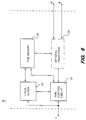
- FIG. 6 illustrates a functional block diagram for the time service block (TSB) shown in Figure 4.
- a local clock 22 is connected to a time control circuit 24, TSB memory 26, and the TPD 6.
- the TSB memory 26 is further connected to the time control circuit 24 and an optional processor 28.
- the time control circuit 24 connects to the TPD 6 and the optional processor 28.
- the time control circuit 24 connects to the basic node function 12 and the LMA 8 either directly or optionally via the optional processor 28.
- the local clock 22 provides a representation of time and can be synchronized and syntonized.
- the local clock 22 contains circuitry that delivers the reading of the clock to the TSB memory 26 upon receipt of a suitable event signal from the TPD 6.
- the local clock 22 receives correction data and signals generated by the time control circuit 24, optionally in conjunction with the optional processor 28, for the synchronization and syntonization functionality.
- the correction data and signals are used to synchronize or syntonize the clock and the event signals are used for recording the TPD event time as measured by the local clock.
- the TSB memory 26 stores captured values of the time received from the local clock 22. These values may be used by the time control circuit 24 or the optional processor 28 for computing the correction factors necessary for the clock adjustments.
- the time control circuit 24 also receives, via the LMA 8, the various timing packets and messages used in computing the various correction factors and for the overall control of the entire TSB 10.
- the time control circuit 24 may deliver optional pattern matching specifications, such as an identifier, to the TPD 6 for additional configuration and detection. The identifier may be used by the time control circuit 24 to associate the local detection time with the synchronization message received from the LMA 8.
- the TSB 10 functionality may be supplemented to support the basic node functionality. Additional functionality may include time, additional memory for event detection, and generating event signals pertinent to the basic node functionality.
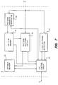
- FIG 7 illustrates a functional block diagram of the time packet detector (TPD) 6 shown in Figure 4.
- TPD control circuit 30 is connected to an optional memory 32, pattern memory 34, a pattern matching circuit 36, a pattern address generator 38, and a start-of-frame detector 40.
- the TPD control circuit 30 connects to the TSB 10.
- the pattern matching circuit 36 connects to the optional memory 32, pattern memory 34, and the LMA 8.
- the pattern address generator 38 further connects to pattern memory 34 and the LMA 8.
- the start-of-frame detector 40 further connects to the LMA 8.
- the start-of-frame detector 40 monitors the incoming data stream and signals the TPD control circuit 30 when a start-of-frame condition is detected.
- the data packet contains a pattern, called the training bit pattern or preamble, that is used by the bit-clock and data recovery block 16 to regenerate the data clock and data stream.
- the end of the preamble is marked by a special pattern that is detected by the start-of-frame detector 40 and indicates that the next bit will be the first bit of the packet header.
- the specifications of the training bit pattern and the start-of-frame mark are different for each communication protocol.
- the start-of-frame detector 40 may be implemented specifically for a given protocol, e.g. Ethernet, or it may be configurable for the protocol currently in use based on configuration data received from the TSB 10 via the TPD control circuit 30.
- the data clock stream is also received by the pattern address generator 38 which generates an address to drive the pattern memory 34.
- the address reflects the bit count of the incoming data stream beginning with the first bit after the start-of-frame condition is detected.
- the pattern address generator 38 is enabled by the TPD control circuit 30 in response to a start-of-frame detector signal that indicates the start of a new frame.
- the pattern memory 34 contains the bit patterns used by the pattern matching circuit 36 for recognizing and detecting the presence of the desired timing packet. These patterns are used by the pattern matching circuit 36 in concert with the corresponding data bit from the LMA 8 based on the address received from the pattern address generator 38. Typically this stream of pattern data will include the bits representing the bit pattern in the packet header or the user data and a mask pattern that indicate which bits are to be checked and which are to be ignored. Together these patterns enable the pattern matching circuit 36 to identify and detect a packet uniquely as being a timing packet. Typically this identification can be made based on address bits in the packet header but the technique works just as well if user data bits are included. For example, with the Ethernet protocol a broadcast address could be assigned to the timing packet and would appear as a unique address in the first six bytes of the packet header. This address would be unique in the system and therefore will enable the pattern matching circuitry to distinguish timing packets from all others.
- the data in the pattern memory 34 is obtained from the TSB 10 via the TPD control circuit 30.
- This data is protocol and application dependent. Certain addresses may be permanently reserved as timing packets by all nodes.
- the patterns and optional control patterns may be loaded permanently into the pattern memory 34.
- a data pattern could be stored that contains a bit indicating that the last bit of the pattern that needs to be checked to determine a match has been processed.
- patterns could be stored that specify a pattern of bits, for example, the identifier bits, that are to be captured and stored in an optional memory 32.
- the optional memory 32 transmits this stored data to the TSB 10 via the TPD control circuit 30.
- the pattern matching circuit 36 receives the incoming data stream from the LMA 8, and the pattern data from the pattern memory 34. When enabled, the pattern matching circuit 36 does a bit-by-bit check on the incoming data stream with respect to the data from the pattern memory 34. Any failure to make an appropriate match is noted and when the end-of-match condition is reached a signal is produced and sent to the TPD control circuit 30 for transfer to the TSB 10 indicating whether the current packet was a timing packet. The time-of-receipt of this signal indicates when the packet was detected. This end-of-match condition can be indicated either by a bit pattern delivered by the pattern memory 34 or a control signal from the TPD control circuit 30 derived from the pattern address generator 38.
- the timing of this end of match condition is known and constant and will depend on the mask pattern defining the bits of interest in the packet and will be consistent throughout the system for a given application.
- the pattern matching circuit 36 may contain optional matching and bit handling circuitry for additional control. Note that this process is jitter free apart from the picosecond level jitter of the individual gates in the pattern matching circuitry logic which will be orders of magnitude less than the remaining jitter from the bit-clock recovery portion of the LMA.
- All of the functionality of the TPD 6, TSB 10, and part of the LMA 8 may be implemented in a single integrated circuit.
- Figure 8 is a timing diagram for the TPD.
- Line A is a data stream.
- Line B is a recovered bit-clock stream.
- Line C is a control bit indicating the start-of-frame.
- Line D is pattern memory address.
- Line E is a target data stream.
- Line F is a mask stream.
- Line G indicates the end-of-match condition.
- Line H is a recognition signal.
- FIG. 9 illustrates a timing diagram when the timing packet detector is used as an event trigger generator.
- Each node is connected to the communication medium.
- Node A initiates a timing packet that is detected at successively later times along the network by the other nodes as indicated in the timing diagram 1.
- the TPD of each node recognizes and detects the timing packet and generates the recognition signal which is used for some application purpose, e.g., closing a relay.
- These pulses will be offset in time from each other by the respective propagation delays. If the propagation delays are measured, as discussed later, then the pulses may be delayed by the TSB of each node by the amount shown resulting in simultaneous pulses as shown in timing diagram 2.
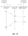
- Figure 10 shows a timing diagram when the timing packet detector is used for measuring the propagation delay, or latency, between two nodes.
- Node A sends timing packet "a" which is seen by the TPD at A at a local time of 100 ns and at the TPD of B at a local time of 80 ns.
- Node B sends timing packet "b" which is seen by the TPD at B at a local time of 200 ns and at the TPD of A at a local time of 300 ns. It is reasonable to assume the delay is symmetric since equivalent delays are encountered by both packets in each node and the medium.
- each node can compute that the A to B apparent propagation time is -20 ns and the B to A apparent propagation time is 100 ns. The average of these is the actual delay, 40 ns. It is also apparent that the local clock in Node B lags the clock in Node A by 60 ns at the time of the experiment.
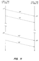
- FIG 11 illustrates the timing diagram when the timing packet detector is used for adjusting the local clocks of two nodes so that they are synchronous and syntonous.
- Node A is the clock initiating synchronization.
- the times of detection of the various packets by the TPDs of each node are noted later.
- the propagation delay between the two nodes has been determined to be 40 ns as in the description of Figure 10.
- Node B receives "s1" and computes an apparent time difference B-A of 140 ns.
- Node B corrects this value by the known propagation delay of 40 ns to conclude that the clock at B is ahead of the clock at A by 100 ns.
- Node B receives "s2" and computes an apparent time difference B-A of 240 ns. Node B corrects this value by the known propagation delay of 40 ns to conclude that the clock at B is ahead of A by 200 ns. Node B resets its local clock back by 200 ns so that it is synchronous with the clock at Node A. Node B computes that between "a1" and "a2", an interval of 1 second on the clock of Node A that the clock of Node B gained 100 ns. Node B then adjusts the rate of its local clock to slow it down by 100 ns/second.
- the clocks of two nodes may be kept in agreement.
- suitable averaging of a series of measurements may be made to reduce further the effect of jitter.
- these basic measurements may be made by an ensemble of nodes and a variety of algorithms, well documented in the literature, applied to produce global agreement of the clocks.
- the timing protocol can be extended to a distributed algorithm by providing each node with full transmitting and receiving capability of the timing packets and synchronization messages.
- each node can perform the computations and actions required by the distributed algorithm.
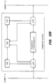
- Figures 12A and 12B illustrate the use of timing packet detectors to overcome jitter and delay in a network.
- Figure 12A illustrates the TPDs as external to the transfer device and
- Figure 12B illustrates the TPDs designed into a transfer device.
- Two subnets of the communication network A and B are shown with a transfer device providing the communication path between the two subnets.
- LMAs and TPDs serving each side of the transfer device and communicating with the respective communication media.
- the two TPDs and LMAs also interact with a common TSB.
- a second technique is to have the TPDs and the TSB at the transfer device record the time that timing packets spend in transit through the transfer device and to report this per packet additional delay to the nodes receiving the timing packet so that they may correct for the additional delay.
- the communication protocol and medium may be different on the A and B sides of the transfer device without loss of accuracy since the delay in the detection process of the two TPDs is constant and can be computed based on the protocol and the detection and recognition pattern.
- the clock of the transfer device may be simultaneously synchronized to a node in a first subnet while acting as the master clock for nodes in the second subnet.
Landscapes
- Engineering & Computer Science (AREA)
- Theoretical Computer Science (AREA)
- Physics & Mathematics (AREA)
- General Engineering & Computer Science (AREA)
- General Physics & Mathematics (AREA)
- Computer Networks & Wireless Communication (AREA)
- Signal Processing (AREA)
- Data Exchanges In Wide-Area Networks (AREA)
- Synchronisation In Digital Transmission Systems (AREA)
- Computer And Data Communications (AREA)
Applications Claiming Priority (2)
| Application Number | Priority Date | Filing Date | Title |
|---|---|---|---|
| US360508 | 1994-12-21 | ||
| US08/360,508 US5566180A (en) | 1994-12-21 | 1994-12-21 | Method for recognizing events and synchronizing clocks |
Publications (3)
| Publication Number | Publication Date |
|---|---|
| EP0722233A2 true EP0722233A2 (de) | 1996-07-17 |
| EP0722233A3 EP0722233A3 (de) | 1997-11-26 |
| EP0722233B1 EP0722233B1 (de) | 2004-09-29 |
Family
ID=23418274
Family Applications (1)
| Application Number | Title | Priority Date | Filing Date |
|---|---|---|---|
| EP95309322A Expired - Lifetime EP0722233B1 (de) | 1994-12-21 | 1995-12-20 | Synchronisierung in einem Datenkommunikationsnetzwerk |
Country Status (4)
| Country | Link |
|---|---|
| US (1) | US5566180A (de) |
| EP (1) | EP0722233B1 (de) |
| JP (2) | JPH08221336A (de) |
| DE (1) | DE69533579T2 (de) |
Cited By (32)
| Publication number | Priority date | Publication date | Assignee | Title |
|---|---|---|---|---|
| WO1998006194A1 (en) * | 1996-08-02 | 1998-02-12 | Medialink Technologies Corporation | Method and apparatus for network clock synchronization |
| WO1999017478A1 (en) * | 1997-09-30 | 1999-04-08 | Northern Telecom Limited | Method for causal ordering in a distributed network |
| EP0971282A1 (de) * | 1998-07-09 | 2000-01-12 | Bull S.A. | Mehrprozessorsystem mit synchronisierter Systemzeit |
| GB2341749A (en) * | 1998-09-19 | 2000-03-22 | Nokia Telecommunications Oy | Digital network synchronisation |
| FR2785751A1 (fr) * | 1998-11-05 | 2000-05-12 | Thomson Multimedia Sa | Procede de synchronisation d'une horloge locale d'un appareil sur l'horloge d'un reseau de communication sans fil et dispositif de synchronisation associe |
| EP1052793A1 (de) * | 1999-05-11 | 2000-11-15 | Canon Kabushiki Kaisha | Verfahren und Vorrichtung zur Synchronisierung zwischen zwei Netzwerken |
| FR2793625A1 (fr) * | 1999-05-11 | 2000-11-17 | Canon Kk | Procede et dispositif de controle de la synchronisation entre deux noeuds de synchronisation |
| FR2793624A1 (fr) * | 1999-05-11 | 2000-11-17 | Canon Kk | Procede et dispositif de controle de la synchronisation entre deux noeuds d'un reseau |
| FR2795261A1 (fr) * | 1999-06-21 | 2000-12-22 | Canon Kk | Procede et dispositif de determination d'un instant de reference lie a la reception de donnees |
| WO2001020827A1 (de) * | 1999-09-13 | 2001-03-22 | Siemens Aktiengesellschaft | Anordnung zum synchronisieren von über ein kommunikationsnetz gekoppelten kommunikationssystemkomponenten |
| WO2001050657A3 (en) * | 1999-12-30 | 2001-12-06 | Ericsson Telefon Ab L M | Synchronization of nodes |
| WO2001088825A3 (en) * | 2000-05-18 | 2002-04-04 | Excel Tech Ltd | Distributed system for patient monitoring and patient data communication using time stamping |
| EP1198085A1 (de) | 2000-10-10 | 2002-04-17 | Sony International (Europe) GmbH | Zyklussynchronisierung zwischen miteinander verbundenen Teilnetzwerken |
| EP1256858A2 (de) * | 2001-05-09 | 2002-11-13 | Agilent Technologies, Inc. (a Delaware corporation) | Modulares System mit synchronisierter Taktung |
| EP1265124A1 (de) * | 2001-06-07 | 2002-12-11 | Siemens Aktiengesellschaft | Verfahren zum Übermitteln von Zeitinformation über ein Datenpaketnetz |
| KR20030019882A (ko) * | 2001-08-30 | 2003-03-07 | 톰슨 라이센싱 소시에떼 아노님 | 모뎀 프런트-엔드 장치 및 그 방법 |
| WO2001089122A3 (en) * | 2000-05-18 | 2003-08-14 | Enterasys Networks Inc | Method and system for distributed clock failure protection in a packet switched network |
| GB2387752A (en) * | 1998-07-22 | 2003-10-22 | Agilent Technologies Inc | A data control system using master and slave cards to communicate timing data via a daisy chain link |
| WO2003047134A3 (de) * | 2001-11-28 | 2003-11-06 | Bridgeco Ag | Verfahren zur synchronisation in netzwerken |
| GB2392353A (en) * | 2002-08-21 | 2004-02-25 | Zarlink Semiconductor Ltd | Method and apparatus for distributing timing data across a packet network |
| WO2004023688A1 (en) * | 2002-09-05 | 2004-03-18 | Koninklijke Philips Electronics N.V. | Apparatus and related method for data synchronization across a w ireless network |
| EP1043912A3 (de) * | 1999-04-06 | 2004-03-31 | Nortel Networks Limited | Selbstkonfigurierender verteilter Vermittler |
| EP1172954A3 (de) * | 2000-03-20 | 2004-11-03 | Alcatel | Verfahren, Module und Programm-Module zur Synchronisierung |
| EP1324520A3 (de) * | 2001-12-24 | 2005-02-09 | Agilent Technologies, Inc. | Synchronisierung in einem verteilten System |
| EP1347356A3 (de) * | 2002-02-15 | 2006-01-11 | Agilent Technologies, Inc. | Zeitschaltung von Instrumenten mit synchronisierten Takten |
| EP1645935A2 (de) | 2004-10-07 | 2006-04-12 | Westerngeco Seismic Holdings Limited | Echtzeituhren Synchronisation in einer Netzwerkumgebung |
| EP1717978A1 (de) * | 2005-04-27 | 2006-11-02 | Rockwell Automation Technologies, Inc. | Zeitsynchronisierung, deterministische Datenübermittlung und Redundanz für kaskadierten Knoten in einem vollduplex-Ethernet Netzwerk |
| US7209454B2 (en) | 1999-04-06 | 2007-04-24 | Nortel Networks Limited | Self-configuring distributed switch |
| US7668182B2 (en) | 2003-02-27 | 2010-02-23 | Smsc Europe Gmbh | Synchronous multi-cluster network architecture |
| EP2159940A1 (de) * | 2008-08-29 | 2010-03-03 | ABB Research LTD | Zeitsynchronisierung in gewerblichen Prozesssteuerung- oder Automatisierungssystemen |
| EP1454500A4 (de) * | 2001-12-12 | 2010-07-07 | Qualcomm Inc | Verfahren, vorrichtung und system zum synchronisieren eines zellularen kommunikationssystems auf gps-zeit |
| EP3351163A1 (de) | 2017-01-20 | 2018-07-25 | Byteflies NV | Verfahren zur bereitstellung von synchronisation zwischen einer vielzahl von drahtlosen körpersensoren und verfahren zum betreiben eines synchronisierten netzwerks von drahtlosen körpersensoren |
Families Citing this family (97)
| Publication number | Priority date | Publication date | Assignee | Title |
|---|---|---|---|---|
| WO1997023765A1 (en) | 1995-12-22 | 1997-07-03 | A/S Brüel & Kjær | A system and a method for measuring a continuous signal |
| DE19626675A1 (de) * | 1996-07-03 | 1998-01-08 | Bosch Gmbh Robert | Verfahren zur Synchronisation |
| US6125368A (en) * | 1997-02-28 | 2000-09-26 | Oracle Corporation | Fault-tolerant timestamp generation for multi-node parallel databases |
| US6370159B1 (en) * | 1998-07-22 | 2002-04-09 | Agilent Technologies, Inc. | System application techniques using time synchronization |
| US6278710B1 (en) * | 1998-09-10 | 2001-08-21 | Agilent Technologies, Inc. | Enhancements to time synchronization in distributed systems |
| US6665316B1 (en) * | 1998-09-29 | 2003-12-16 | Agilent Technologies, Inc. | Organization of time synchronization in a distributed system |
| US6236623B1 (en) | 1998-10-16 | 2001-05-22 | Moore Industries | System and method for synchronizing clocks in a plurality of devices across a communication channel |
| US6654356B1 (en) * | 1998-10-29 | 2003-11-25 | Agilent Technologies, Inc. | Distributed control system architecture based on synchronized clocks |
| US6449291B1 (en) * | 1998-11-24 | 2002-09-10 | 3Com Corporation | Method and apparatus for time synchronization in a communication system |
| US6998996B1 (en) * | 1998-12-03 | 2006-02-14 | Agilent Technologies, Inc. | Motion control using time synchronization |
| FR2793623B1 (fr) * | 1999-05-11 | 2003-01-24 | Canon Kk | Procede et dispositif de controle de la synchronisation entre deux noeuds ni-1, ni d'un reseau |
| US6621767B1 (en) | 1999-07-14 | 2003-09-16 | Guide Technology, Inc. | Time interval analyzer having real time counter |
| US6181649B1 (en) | 1999-07-14 | 2001-01-30 | Guide Technology, Inc. | Time interval analyzer having current boost |
| US6456959B1 (en) | 1999-07-14 | 2002-09-24 | Guide Technology, Inc. | Time interval analyzer having parallel counters |
| US6226231B1 (en) * | 1999-07-14 | 2001-05-01 | Guide Technology, Inc. | Time interval analyzer having multiple measurement circuits |
| US6091671A (en) * | 1999-07-14 | 2000-07-18 | Guide Technology, Inc. | Time interval analyzer having interpolator with constant current capacitor control |
| JP3480701B2 (ja) * | 1999-08-06 | 2003-12-22 | 日本電気株式会社 | パケットネットワーク伝送遅延測定方法およびプログラムを記録した機械読み取り可能な記録媒体 |
| FI115494B (fi) * | 1999-09-08 | 2005-05-13 | Nokia Corp | Tukiaseman taajuussynkronointi |
| US6577648B1 (en) * | 1999-10-04 | 2003-06-10 | Nokia Corporation | Method and apparatus for determining VoIP QoS characteristics of a network using multiple streams of packets and synchronizing measurements of the streams |
| US6631144B1 (en) * | 1999-12-21 | 2003-10-07 | Intel Corporation | Multi-rate transponder system and chip set |
| US6751573B1 (en) * | 2000-01-10 | 2004-06-15 | Agilent Technologies, Inc. | Performance monitoring in distributed systems using synchronized clocks and distributed event logs |
| JP2001223726A (ja) * | 2000-02-10 | 2001-08-17 | Toyo Microsystems Corp | 多重通信方法、多重通信装置および多重通信システム |
| US6882634B2 (en) * | 2000-04-07 | 2005-04-19 | Broadcom Corporation | Method for selecting frame encoding parameters to improve transmission performance in a frame-based communications network |
| US6985499B2 (en) | 2000-04-20 | 2006-01-10 | Symmetricom, Inc. | Precise network time transfer |
| US6874096B1 (en) | 2000-06-23 | 2005-03-29 | 2Wire, Inc. | Apparatus and method for detecting packet arrival time |
| US7072999B1 (en) * | 2000-06-27 | 2006-07-04 | 2Wire, Inc. | Robust packet arrival time detector using estimated signal power |
| US6944187B1 (en) * | 2000-08-09 | 2005-09-13 | Alcatel Canada Inc. | Feature implementation in a real time stamp distribution system |
| JP2002077092A (ja) * | 2000-09-01 | 2002-03-15 | Sony Corp | 多重装置、受信装置及び多重伝送方法 |
| US6470031B1 (en) * | 2000-09-05 | 2002-10-22 | Coactive Networks, Inc. | Method and apparatus for accurate packet time stamping |
| DE10113261C2 (de) * | 2001-03-16 | 2003-07-10 | Siemens Ag | Synchrones, getaktetes Kommunikationssystem mit dezentralen Ein-/Ausgabe-Baugruppen und Verfahren zur Einbindung dezentraler Ein-/Ausgabe-Baugruppen in ein solches System |
| JP2002300482A (ja) * | 2001-03-30 | 2002-10-11 | Sanyo Electric Co Ltd | デジタルテレビ放送受信機 |
| US7251246B2 (en) | 2001-09-14 | 2007-07-31 | Snowshore Networks, Inc. | Selective packet processing in a packet based media processor for latency reduction |
| EP1430627B1 (de) * | 2001-09-26 | 2005-02-09 | Siemens Aktiengesellschaft | Verfahren zur synchronisation von knoten eines kommunikationssystems |
| US7099354B2 (en) * | 2002-01-24 | 2006-08-29 | Radioframe Networks, Inc. | Method and apparatus for frequency and timing distribution through a packet-based network |
| GB2385684A (en) * | 2002-02-22 | 2003-08-27 | Sony Uk Ltd | Frequency synchronisation of clocks |
| US7114091B2 (en) * | 2002-03-18 | 2006-09-26 | National Instruments Corporation | Synchronization of distributed systems |
| US7567509B2 (en) * | 2002-09-13 | 2009-07-28 | Dialogic Corporation | Methods and systems for jitter minimization in streaming media |
| US7684413B2 (en) * | 2002-10-09 | 2010-03-23 | Juniper Networks, Inc. | System and method for rate agile adaptive clocking in a packet-based network |
| US7668092B2 (en) * | 2002-11-21 | 2010-02-23 | Honeywell International Inc. | Data transmission system and method |
| US7230884B2 (en) * | 2003-01-03 | 2007-06-12 | The Sapling Company, Inc. | Clock diagnostics |
| US7379480B2 (en) * | 2003-01-16 | 2008-05-27 | Rockwell Automation Technologies, Inc. | Fast frequency adjustment method for synchronizing network clocks |
| EP1595347A1 (de) * | 2003-02-20 | 2005-11-16 | Zarlink Semiconductor Inc. | Verfahren zur bereitstellung von verteilungsmitteln für referenztakte über paketierte netzwerke hinweg |
| US8432942B1 (en) | 2003-05-16 | 2013-04-30 | Apple Inc. | Providing a timing source for multiple nodes coupled to a circuit-switched network |
| US7397823B2 (en) * | 2003-06-04 | 2008-07-08 | Agilent Technologies, Inc. | Providing time synchronization across store-and-forward communication devices using protocol-enabled switches |
| US7570669B2 (en) * | 2003-08-08 | 2009-08-04 | Opnet Technologies, Inc. | Synchronizing packet traces |
| US7308002B2 (en) * | 2003-11-24 | 2007-12-11 | Intergrated System Solution Corp. | Packet type arbitrator in WLAN and corresponding arbitrating method |
| US7315791B2 (en) * | 2004-02-18 | 2008-01-01 | National Instruments Corporation | Application programming interface for synchronizing multiple instrumentation devices |
| US8930579B2 (en) * | 2004-09-13 | 2015-01-06 | Keysight Technologies, Inc. | System and method for synchronizing operations of a plurality of devices via messages over a communication network |
| US7561598B2 (en) * | 2004-09-13 | 2009-07-14 | Agilent Technologies, Inc. | Add-on module for synchronizing operations of a plurality of devices |
| US7593429B2 (en) * | 2004-10-14 | 2009-09-22 | Temic Automotive Of North America, Inc. | System and method for time synchronizing nodes in an automotive network using input capture |
| WO2006044140A2 (en) * | 2004-10-14 | 2006-04-27 | Motorola, Inc. | System and method for time synchronizing nodes in an automotive network |
| US7623552B2 (en) | 2004-10-14 | 2009-11-24 | Temic Automotive Of North America, Inc. | System and method for time synchronizing nodes in an automotive network using input capture |
| US7593344B2 (en) * | 2004-10-14 | 2009-09-22 | Temic Automotive Of North America, Inc. | System and method for reprogramming nodes in an automotive switch fabric network |
| US20060083172A1 (en) * | 2004-10-14 | 2006-04-20 | Jordan Patrick D | System and method for evaluating the performance of an automotive switch fabric network |
| US7599377B2 (en) * | 2004-10-15 | 2009-10-06 | Temic Automotive Of North America, Inc. | System and method for tunneling standard bus protocol messages through an automotive switch fabric network |
| US7613190B2 (en) * | 2004-10-18 | 2009-11-03 | Temic Automotive Of North America, Inc. | System and method for streaming sequential data through an automotive switch fabric |
| US7904184B2 (en) * | 2004-11-23 | 2011-03-08 | Rockwell Automation Technologies, Inc. | Motion control timing models |
| US7983769B2 (en) * | 2004-11-23 | 2011-07-19 | Rockwell Automation Technologies, Inc. | Time stamped motion control network protocol that enables balanced single cycle timing and utilization of dynamic data structures |
| US7814205B2 (en) * | 2005-12-15 | 2010-10-12 | Motorola, Inc. | Method and apparatus for managing floor control in a network |
| US20070185689A1 (en) * | 2006-02-07 | 2007-08-09 | Sigcom, Inc. | Systems and methods for event detection and logging in access control points |
| US20070248122A1 (en) * | 2006-04-19 | 2007-10-25 | Bruce Hamilton | Methods and systems relating to distributed time markers |
| US20070258378A1 (en) * | 2006-05-05 | 2007-11-08 | Bruce Hamilton | Methods and systems relating to distributed time markers |
| US20070260906A1 (en) * | 2006-05-08 | 2007-11-08 | Corredoura Paul L | Clock synchronization method and apparatus |
| US20080031283A1 (en) * | 2006-08-07 | 2008-02-07 | Martin Curran-Gray | Time synchronization for network aware devices |
| US8325767B2 (en) * | 2006-09-29 | 2012-12-04 | Agilent Technologies, Inc. | Enhancement of IEEE 1588 synchronization using out-of-band communication path |
| US7912094B2 (en) * | 2006-12-13 | 2011-03-22 | Honeywell International Inc. | Self-checking pair-based master/follower clock synchronization |
| WO2008138052A1 (en) * | 2007-05-15 | 2008-11-20 | Chronologic Pty Ltd | Method and system for reducing triggering latency in universal serial bus data acquisition |
| US7778283B2 (en) | 2007-06-04 | 2010-08-17 | Agilent Technologies, Inc. | Timing bridge device |
| US20090010283A1 (en) * | 2007-07-03 | 2009-01-08 | Arcadyan Technology Corporation | Synchronization method of electronic apparatuses |
| EP2034642B1 (de) * | 2007-09-07 | 2011-10-26 | Siemens Aktiengesellschaft | Verfahren zur Übertragung von Synchronisationsnachrichten in einem Kommunikationsnetz |
| US8050881B1 (en) | 2007-10-18 | 2011-11-01 | Enbiomedic | Post data-collection synchronization for approximation of simultaneous data |
| US8559412B1 (en) | 2007-12-31 | 2013-10-15 | Rockstar Consortium Us Lp | Communication time information in a network to enable synchronization |
| US8073976B2 (en) * | 2008-03-27 | 2011-12-06 | Microsoft Corporation | Synchronizing clocks in an asynchronous distributed system |
| US7738504B1 (en) * | 2008-12-22 | 2010-06-15 | The United States Of America As Represented By The Director National Security Agency | Method of establishing and updating master node in computer network |
| FI121771B (fi) * | 2009-01-16 | 2011-03-31 | Tellabs Oy | Menetelmä ja järjestely kellosignaalin säätämiseksi |
| CA2761377A1 (en) | 2009-05-20 | 2010-11-25 | Peter Graham Foster | Synchronous network of superspeed and non-superspeed usb devices |
| US8385333B2 (en) * | 2009-06-30 | 2013-02-26 | Intel Corporation | Mechanism for clock synchronization |
| WO2011021115A1 (en) * | 2009-08-17 | 2011-02-24 | Koninklijke Philips Electronics, N.V. | System and method to synchronize a patient monitoring device with a central server |
| US8428045B2 (en) * | 2010-03-16 | 2013-04-23 | Harman International Industries, Incorporated | Media clock recovery |
| US8307235B2 (en) | 2010-05-05 | 2012-11-06 | National Instruments Corporation | Cross controller clock synchronization |
| US9606219B2 (en) | 2010-08-02 | 2017-03-28 | Progeny Systems Corporation | Systems and methods for locating a target in a GPS-denied environment |
| EP2527935B1 (de) * | 2011-05-26 | 2014-12-03 | Siemens Aktiengesellschaft | Verfahren zum Betrieb eines Automatisierungssystems |
| US9756153B2 (en) | 2011-06-01 | 2017-09-05 | Finite State Research Llc | Method for improving accuracy in computation of one-way transfer time for network time synchronization |
| US9588544B2 (en) * | 2011-06-06 | 2017-03-07 | Microsoft Technology Licensing, Llc | Time synchronization across computers in a distributed system |
| US8644350B2 (en) * | 2011-11-23 | 2014-02-04 | Vitesse Semiconductor Corporation | Packet-based timing measurement |
| US9075545B2 (en) * | 2012-08-01 | 2015-07-07 | Hewlett-Packard Development Company, L.P. | Synchronizing sensor data using timestamps and signal interpolation |
| US9628209B2 (en) | 2013-01-17 | 2017-04-18 | Viavi Solutions Inc. | Time synchronization in distributed network testing equipment |
| US9759703B2 (en) | 2013-09-27 | 2017-09-12 | Li-Cor, Inc. | Systems and methods for measuring gas flux |
| US10212226B2 (en) | 2014-01-16 | 2019-02-19 | Hewlett Packard Enterprise Development Lp | Node cluster synchronization |
| US20160006526A1 (en) * | 2014-07-03 | 2016-01-07 | Qualcomm Incorporated | Systems and methods of network clock comparison |
| EP3224789B1 (de) * | 2014-09-07 | 2026-02-11 | Codrut Radu Radulescu | System mit relativer fraktioneller zeitmessung |
| KR101689077B1 (ko) * | 2015-04-14 | 2016-12-22 | 엘에스산전 주식회사 | 시간 동기화 방법 및 그 장치 |
| US10848160B2 (en) | 2018-07-10 | 2020-11-24 | Aerotech, Inc. | Devices, systems, and methods for reducing jitter in control systems |
| US10809759B2 (en) | 2018-09-04 | 2020-10-20 | Microsoft Technology Licensing, Llc | Application compatible leap second support |
| EP3946646A4 (de) * | 2019-04-01 | 2023-01-04 | Tgoma Nz Limited | Synchronisierungssystem und -verfahren |
| US11435463B2 (en) * | 2020-06-03 | 2022-09-06 | Forkbeard Technologies AS | Master-less device coordination in location positioning system |
| EP3958511B1 (de) * | 2020-08-19 | 2023-06-07 | Televic Conference NV | Drahtloses konferenzsystem mit früherkennung von paketverlusten |
Family Cites Families (4)
| Publication number | Priority date | Publication date | Assignee | Title |
|---|---|---|---|---|
| AT382253B (de) * | 1984-06-22 | 1987-02-10 | Austria Mikrosysteme Int | Lose gekoppeltes verteiltes computersystem |
| US4748620A (en) * | 1986-02-28 | 1988-05-31 | American Telephone And Telegraph Company, At&T Bell Laboratories | Time stamp and packet virtual sequence numbering for reconstructing information signals from packets |
| EP0247026A3 (de) * | 1986-05-16 | 1989-09-06 | Austria Mikrosysteme International Gmbh | Verfahren zur Synchronisation der Echtzeituhren von an ein Kommunikationsmedium angeschlossenen Knotenrechnern und Knotenrechner zur Durchführung des Verfahrens |
| US4893318A (en) * | 1988-01-26 | 1990-01-09 | Computer Sports Medicine, Inc. | Method for referencing multiple data processors to a common time reference |
-
1994
- 1994-12-21 US US08/360,508 patent/US5566180A/en not_active Expired - Lifetime
-
1995
- 1995-11-30 JP JP7312169A patent/JPH08221336A/ja active Pending
- 1995-12-20 DE DE69533579T patent/DE69533579T2/de not_active Expired - Fee Related
- 1995-12-20 EP EP95309322A patent/EP0722233B1/de not_active Expired - Lifetime
-
2005
- 2005-10-28 JP JP2005314795A patent/JP2006101539A/ja active Pending
Cited By (56)
| Publication number | Priority date | Publication date | Assignee | Title |
|---|---|---|---|---|
| WO1998006194A1 (en) * | 1996-08-02 | 1998-02-12 | Medialink Technologies Corporation | Method and apparatus for network clock synchronization |
| WO1999017478A1 (en) * | 1997-09-30 | 1999-04-08 | Northern Telecom Limited | Method for causal ordering in a distributed network |
| US6052363A (en) * | 1997-09-30 | 2000-04-18 | Northern Telecom Limited | Method for causal ordering in a distributed network |
| EP0971282A1 (de) * | 1998-07-09 | 2000-01-12 | Bull S.A. | Mehrprozessorsystem mit synchronisierter Systemzeit |
| GB2387752A (en) * | 1998-07-22 | 2003-10-22 | Agilent Technologies Inc | A data control system using master and slave cards to communicate timing data via a daisy chain link |
| GB2387752B (en) * | 1998-07-22 | 2004-02-04 | Agilent Technologies Inc | Data acquisition and control system |
| GB2341749A (en) * | 1998-09-19 | 2000-03-22 | Nokia Telecommunications Oy | Digital network synchronisation |
| FR2785751A1 (fr) * | 1998-11-05 | 2000-05-12 | Thomson Multimedia Sa | Procede de synchronisation d'une horloge locale d'un appareil sur l'horloge d'un reseau de communication sans fil et dispositif de synchronisation associe |
| WO2000028401A1 (fr) * | 1998-11-05 | 2000-05-18 | Thomson Multimedia | Procede et dispositif de synchronisation d'une horloge locale sur l'horloge d'un reseau de communication sans fil |
| EP1043912A3 (de) * | 1999-04-06 | 2004-03-31 | Nortel Networks Limited | Selbstkonfigurierender verteilter Vermittler |
| US7209454B2 (en) | 1999-04-06 | 2007-04-24 | Nortel Networks Limited | Self-configuring distributed switch |
| US7230952B2 (en) | 1999-04-06 | 2007-06-12 | Nortel Networks Ltd | Self-configuring distributed switch |
| FR2793625A1 (fr) * | 1999-05-11 | 2000-11-17 | Canon Kk | Procede et dispositif de controle de la synchronisation entre deux noeuds de synchronisation |
| EP1052793A1 (de) * | 1999-05-11 | 2000-11-15 | Canon Kabushiki Kaisha | Verfahren und Vorrichtung zur Synchronisierung zwischen zwei Netzwerken |
| FR2793624A1 (fr) * | 1999-05-11 | 2000-11-17 | Canon Kk | Procede et dispositif de controle de la synchronisation entre deux noeuds d'un reseau |
| US6954471B1 (en) | 1999-06-21 | 2005-10-11 | Canon Kabushiki Kaisha | Method and device of generation of one reference event from a frame of information |
| FR2795261A1 (fr) * | 1999-06-21 | 2000-12-22 | Canon Kk | Procede et dispositif de determination d'un instant de reference lie a la reception de donnees |
| EP1063808A3 (de) * | 1999-06-21 | 2001-01-24 | Canon Kabushiki Kaisha | Verfahren und Vorrichtung zur Generierung eines Referenzereignisses aus einem Informationsrahmen |
| WO2001020827A1 (de) * | 1999-09-13 | 2001-03-22 | Siemens Aktiengesellschaft | Anordnung zum synchronisieren von über ein kommunikationsnetz gekoppelten kommunikationssystemkomponenten |
| US7085276B1 (en) | 1999-09-13 | 2006-08-01 | Siemens Aktiengesellschaft | System for synchronizing communications system components coupled via a communications network |
| WO2001050657A3 (en) * | 1999-12-30 | 2001-12-06 | Ericsson Telefon Ab L M | Synchronization of nodes |
| US7103124B1 (en) | 1999-12-30 | 2006-09-05 | Telefonaktiebolaget Lm Ericsson (Publ) | Synchronization of nodes |
| EP1172954A3 (de) * | 2000-03-20 | 2004-11-03 | Alcatel | Verfahren, Module und Programm-Module zur Synchronisierung |
| WO2001089122A3 (en) * | 2000-05-18 | 2003-08-14 | Enterasys Networks Inc | Method and system for distributed clock failure protection in a packet switched network |
| US6754171B1 (en) | 2000-05-18 | 2004-06-22 | Enterasys Networks, Inc. | Method and system for distributed clock failure protection in a packet switched network |
| WO2001088825A3 (en) * | 2000-05-18 | 2002-04-04 | Excel Tech Ltd | Distributed system for patient monitoring and patient data communication using time stamping |
| US7720110B2 (en) | 2000-10-10 | 2010-05-18 | Sony Deutschland Gmbh | Cycle synchronization between interconnected sub-networks |
| EP1198085A1 (de) | 2000-10-10 | 2002-04-17 | Sony International (Europe) GmbH | Zyklussynchronisierung zwischen miteinander verbundenen Teilnetzwerken |
| US7184449B2 (en) | 2000-10-10 | 2007-02-27 | Sony Deutschland Gmbh | Cycle synchronization between interconnected sub-networks |
| EP1256858A2 (de) * | 2001-05-09 | 2002-11-13 | Agilent Technologies, Inc. (a Delaware corporation) | Modulares System mit synchronisierter Taktung |
| EP1265124A1 (de) * | 2001-06-07 | 2002-12-11 | Siemens Aktiengesellschaft | Verfahren zum Übermitteln von Zeitinformation über ein Datenpaketnetz |
| US7372846B2 (en) | 2001-06-07 | 2008-05-13 | Siemens Aktiengesellschaft | Method for transmitting time information via a data packet network |
| EP1294168A3 (de) * | 2001-08-30 | 2004-08-04 | Thomson Licensing S.A. | Verfahren und Gerät fur ein Frontendmodem |
| KR20030019882A (ko) * | 2001-08-30 | 2003-03-07 | 톰슨 라이센싱 소시에떼 아노님 | 모뎀 프런트-엔드 장치 및 그 방법 |
| US7006457B2 (en) | 2001-08-30 | 2006-02-28 | Thomson Licensing | Modem front-end apparatus and method |
| WO2003047134A3 (de) * | 2001-11-28 | 2003-11-06 | Bridgeco Ag | Verfahren zur synchronisation in netzwerken |
| US8601165B2 (en) | 2001-11-28 | 2013-12-03 | Smsc Holdings S.A.R.L. | Method for synchronization in networks |
| US7716375B2 (en) | 2001-11-28 | 2010-05-11 | Bridgeco Ag | Method for synchronization in networks |
| EP1454500A4 (de) * | 2001-12-12 | 2010-07-07 | Qualcomm Inc | Verfahren, vorrichtung und system zum synchronisieren eines zellularen kommunikationssystems auf gps-zeit |
| EP1324520A3 (de) * | 2001-12-24 | 2005-02-09 | Agilent Technologies, Inc. | Synchronisierung in einem verteilten System |
| US7251199B2 (en) | 2001-12-24 | 2007-07-31 | Agilent Technologies, Inc. | Distributed system time synchronization including a timing signal path |
| EP1347356A3 (de) * | 2002-02-15 | 2006-01-11 | Agilent Technologies, Inc. | Zeitschaltung von Instrumenten mit synchronisierten Takten |
| GB2392353B (en) * | 2002-08-21 | 2005-11-02 | Zarlink Semiconductor Ltd | Method and apparatus for distributing timing data across a packet network |
| GB2392353A (en) * | 2002-08-21 | 2004-02-25 | Zarlink Semiconductor Ltd | Method and apparatus for distributing timing data across a packet network |
| US7508843B2 (en) | 2002-08-21 | 2009-03-24 | Zarlink Semiconductor Limited | Method and apparatus for distributing timing data across a packet network |
| WO2004023688A1 (en) * | 2002-09-05 | 2004-03-18 | Koninklijke Philips Electronics N.V. | Apparatus and related method for data synchronization across a w ireless network |
| US7668182B2 (en) | 2003-02-27 | 2010-02-23 | Smsc Europe Gmbh | Synchronous multi-cluster network architecture |
| US7768931B2 (en) | 2004-10-07 | 2010-08-03 | Westerngeco L.L.C. | Hardware-based network packet timestamps: improved network clock synchronization |
| EP1645935A3 (de) * | 2004-10-07 | 2008-04-09 | Westerngeco Seismic Holdings Limited | Echtzeituhren Synchronisation in einer Netzwerkumgebung |
| EP1645935A2 (de) | 2004-10-07 | 2006-04-12 | Westerngeco Seismic Holdings Limited | Echtzeituhren Synchronisation in einer Netzwerkumgebung |
| EP1717978A1 (de) * | 2005-04-27 | 2006-11-02 | Rockwell Automation Technologies, Inc. | Zeitsynchronisierung, deterministische Datenübermittlung und Redundanz für kaskadierten Knoten in einem vollduplex-Ethernet Netzwerk |
| US7649912B2 (en) | 2005-04-27 | 2010-01-19 | Rockwell Automation Technologies, Inc. | Time synchronization, deterministic data delivery and redundancy for cascaded nodes on full duplex ethernet networks |
| WO2010023175A1 (en) * | 2008-08-29 | 2010-03-04 | Abb Research Ltd | Time synchronization in industrial process control or automation systems |
| EP2159940A1 (de) * | 2008-08-29 | 2010-03-03 | ABB Research LTD | Zeitsynchronisierung in gewerblichen Prozesssteuerung- oder Automatisierungssystemen |
| EP3351163A1 (de) | 2017-01-20 | 2018-07-25 | Byteflies NV | Verfahren zur bereitstellung von synchronisation zwischen einer vielzahl von drahtlosen körpersensoren und verfahren zum betreiben eines synchronisierten netzwerks von drahtlosen körpersensoren |
| WO2018134380A1 (en) | 2017-01-20 | 2018-07-26 | Byteflies N.V. | Method for providing synchronization between a plurality of wireless body sensors and method for operating a synchronized network of wireless body sensors |
Also Published As
| Publication number | Publication date |
|---|---|
| JPH08221336A (ja) | 1996-08-30 |
| EP0722233B1 (de) | 2004-09-29 |
| EP0722233A3 (de) | 1997-11-26 |
| DE69533579T2 (de) | 2006-02-23 |
| US5566180A (en) | 1996-10-15 |
| DE69533579D1 (de) | 2004-11-04 |
| JP2006101539A (ja) | 2006-04-13 |
Similar Documents
| Publication | Publication Date | Title |
|---|---|---|
| EP0722233B1 (de) | Synchronisierung in einem Datenkommunikationsnetzwerk | |
| CN102647270B (zh) | 航空电子设备网络中的自由运转节点的时间同步方法 | |
| US8576883B2 (en) | Measurement and adjustment of real-time values according to residence time in networking equipment without access to real time | |
| EP0986202B1 (de) | Verbesserungen der Zeitsynchronisierung in verteilten Systemen | |
| US7251199B2 (en) | Distributed system time synchronization including a timing signal path | |
| JP3902592B2 (ja) | リアルタイム処理用の分散型システムのノードの同期方法及び同期ユニット | |
| US8295267B2 (en) | Clock synchronization system, method, and apparatus for communication | |
| CN1934809B (zh) | 由不可靠数据分组网络分离时校准时间基准的方法和装置 | |
| EP2288070B1 (de) | Verfahren, vorrichtung und system zur zeitsynchronisierung der mastertakseite und der strukturseite in einem sychronen netzwerk | |
| US20020024973A1 (en) | Hardware time stamping and registration of packetized data method and system | |
| JP2000332802A (ja) | 通信方法、通信システム、通信端末および中継装置 | |
| JP2010541298A (ja) | センサネットワークにおける時間同期に関する方法及びシステム | |
| US10298345B2 (en) | Clock synchronizaton using codeword marker | |
| US20020021717A1 (en) | Method and system for transmit time stamp insertion in a hardware time stamp system for packetized data networks | |
| EP1629614A1 (de) | Zeitgesteuertes kommunikationsystem und verfahren zur synchronisation eines zweikanaligen netzes | |
| US11445341B2 (en) | Dynamic weighing device | |
| US12294451B2 (en) | System and methods for network data processing | |
| JP3571218B2 (ja) | 同期動作システム | |
| EP1598968B1 (de) | Verbesserungen der Zeitsynchronisierung in verteilten Systemen | |
| CN114499734B (zh) | 基于ptp的通讯时钟同步方法、系统和设备 | |
| FI108976B (fi) | Menetelmä paikallistosiaikalaskureiden synkronoimiseksi | |
| CN119402118A (zh) | 基于全局时钟同步的afdx终端时间高完整性校验方法 | |
| JP2001069162A (ja) | ループ型データ伝送システム | |
| JPH0435934B2 (de) |
Legal Events
| Date | Code | Title | Description |
|---|---|---|---|
| PUAI | Public reference made under article 153(3) epc to a published international application that has entered the european phase |
Free format text: ORIGINAL CODE: 0009012 |
|
| AK | Designated contracting states |
Kind code of ref document: A2 Designated state(s): DE FR GB |
|
| PUAL | Search report despatched |
Free format text: ORIGINAL CODE: 0009013 |
|
| AK | Designated contracting states |
Kind code of ref document: A3 Designated state(s): DE FR GB |
|
| 17P | Request for examination filed |
Effective date: 19980525 |
|
| RAP1 | Party data changed (applicant data changed or rights of an application transferred) |
Owner name: HEWLETT-PACKARD COMPANY, A DELAWARE CORPORATION |
|
| RAP1 | Party data changed (applicant data changed or rights of an application transferred) |
Owner name: AGILENT TECHNOLOGIES, INC. Owner name: HEWLETT-PACKARD COMPANY, A DELAWARE CORPORATION |
|
| RAP1 | Party data changed (applicant data changed or rights of an application transferred) |
Owner name: AGILENT TECHNOLOGIES, INC. |
|
| RAP1 | Party data changed (applicant data changed or rights of an application transferred) |
Owner name: AGILENT TECHNOLOGIES INC. |
|
| RAP1 | Party data changed (applicant data changed or rights of an application transferred) |
Owner name: AGILENT TECHNOLOGIES INC. A DELAWARE CORPORATION |
|
| RAP1 | Party data changed (applicant data changed or rights of an application transferred) |
Owner name: AGILENT TECHNOLOGIES, INC. (A DELAWARE CORPORATION |
|
| RAP1 | Party data changed (applicant data changed or rights of an application transferred) |
Owner name: HEWLETT-PACKARD COMPANY (A DELAWARE CORPORATION) Owner name: AGILENT TECHNOLOGIES, INC. (A DELAWARE CORPORATION |
|
| 17Q | First examination report despatched |
Effective date: 20020604 |
|
| GRAP | Despatch of communication of intention to grant a patent |
Free format text: ORIGINAL CODE: EPIDOSNIGR1 |
|
| GRAS | Grant fee paid |
Free format text: ORIGINAL CODE: EPIDOSNIGR3 |
|
| GRAA | (expected) grant |
Free format text: ORIGINAL CODE: 0009210 |
|
| AK | Designated contracting states |
Kind code of ref document: B1 Designated state(s): DE FR GB |
|
| REG | Reference to a national code |
Ref country code: GB Ref legal event code: FG4D |
|
| REF | Corresponds to: |
Ref document number: 69533579 Country of ref document: DE Date of ref document: 20041104 Kind code of ref document: P |
|
| PLBE | No opposition filed within time limit |
Free format text: ORIGINAL CODE: 0009261 |
|
| STAA | Information on the status of an ep patent application or granted ep patent |
Free format text: STATUS: NO OPPOSITION FILED WITHIN TIME LIMIT |
|
| ET | Fr: translation filed | ||
| 26N | No opposition filed |
Effective date: 20050630 |
|
| REG | Reference to a national code |
Ref country code: GB Ref legal event code: 732E |
|
| PGFP | Annual fee paid to national office [announced via postgrant information from national office to epo] |
Ref country code: FR Payment date: 20061220 Year of fee payment: 12 |
|
| PGFP | Annual fee paid to national office [announced via postgrant information from national office to epo] |
Ref country code: GB Payment date: 20061222 Year of fee payment: 12 |
|
| GBPC | Gb: european patent ceased through non-payment of renewal fee |
Effective date: 20071220 |
|
| REG | Reference to a national code |
Ref country code: FR Ref legal event code: ST Effective date: 20081020 |
|
| PG25 | Lapsed in a contracting state [announced via postgrant information from national office to epo] |
Ref country code: GB Free format text: LAPSE BECAUSE OF NON-PAYMENT OF DUE FEES Effective date: 20071220 |
|
| PG25 | Lapsed in a contracting state [announced via postgrant information from national office to epo] |
Ref country code: FR Free format text: LAPSE BECAUSE OF NON-PAYMENT OF DUE FEES Effective date: 20071231 |
|
| PGFP | Annual fee paid to national office [announced via postgrant information from national office to epo] |
Ref country code: DE Payment date: 20081219 Year of fee payment: 14 |
|
| PG25 | Lapsed in a contracting state [announced via postgrant information from national office to epo] |
Ref country code: DE Free format text: LAPSE BECAUSE OF NON-PAYMENT OF DUE FEES Effective date: 20100701 |